Hitachi DH24PB Manuel utilisateur
- Catégorie
- Outils électroportatifs
- Taper
- Manuel utilisateur
Ce manuel convient également à

DH 24PB
MODEL ROTARY HAMMER
MODÈLE MARTEAU ROTATIF
MODELO MARTILLO GIRATORIO
DOUBLE INSULATION
DOUBLE ISOLATION
AISLAMIENTO DOBLE
MODE D’EMPLOI ET INSTRUCTIONS DE SECURITE
AVERTISSEMENT
Une utilisation incorrecte et dangereuse de cet outil motorisé peut entraîner la
mort ou de sérieuses blessures corporelles!
Ce mode d’emploi contient d’importantes informations à propos de la sécurité de
ce produit. Prière de lire et de comprendre ce mode d’emploi avant d’utiliser l’outil
motorisé. Garder ce mode d’emploi à la disponibilité des autres utilisateurs avant
qu’ils utilisent l’outil motorisé.
INSTRUCTION MANUAL AND SAFETY INSTRUCTIONS
WARNING
Improper and unsafe use of this power tool can result in death or serious bodily
injury!
This manual contains important information about product safety. Please read
and understand this manual before operating the power tool. Please keep this
manual available for others before they use the power tool.
MANUAL DE INSTRUCCIONES E INSTRUCCIONES DE SEGURIDAD
ADVERTENCIA
¡La utilización inapropiada e insegura de esta herramienta eléctrica puede resultar
en lesiones serias o en la muerte!
Este manual contiene información importante sobre la seguridad del producto.
Lea y comprenda este manual antes de utilizar la herramienta eléctrica. Guarde
este manual para que puedan leerlo otras personas antes de que utilicen la
herramienta eléctrica.

2
English
CONTENTS
English
Page
IMPORTANT INFORMATION ............. 3
MEANINGS OF SIGNAL WORDS ...... 3
SAFETY ................................................... 4
GENERAL SAFETY RULES ................. 4
SPECIFIC SAFETY RULES AND SYMBOLS
..... 7
DOUBLE INSULATION FOR SAFER
OPERATION ..................................... 8
FUNCTIONAL DESCRIPTION ................ 9
MANE OF PARTS ................................ 9
SPECIFICATIONS ................................ 9
Page
ASSEMBLY AND OPERATION ............ 10
APPLICATIONS ................................. 10
PRIOR TO OPERATION ..................... 10
HOW TO USE .................................... 12
HOW TO USE THE CORE BIT (FOR LIGHT LOAD)
... 15
MAINTENANCE AND INSPECTION .... 17
ACCESSORIES ...................................... 18
STANDARD ACCESSORIES ............. 18
OPTIONAL ACCESSORIES ............... 18
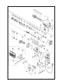
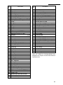
PARTS LIST .......................................... 68
TABLE DES MATIERES
Français
Page
INFORMATIONS IMPORTANTES ....... 24
SIGNIFICATION DES MOTS
D’AVERTISSEMENT ......................... 24
SECURITE ............................................. 25
REGLES GENERALES DE SECURITE
..... 25
REGLES DE SECURITE SPECIFIQUES ET SYMBOLES
... 28
DOUBLE ISOLATION POUR UN
FONCTIONNEMENT PLUS SUR
........ 29
DESCRIPTION FONCTIONNELLE ........ 30
NOM DES PARTIES .......................... 30
SPECIFICATIONS .............................. 30
Page
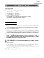
ASSEMBLAGE ET FONCTIONNEMENT ....
31
APPLICATIONS ................................. 31
AVANT L’UTILISATION .................... 31
UTILISATION ..................................... 33
COMMENT UTILISER LA COURONNE (POUR
UNE CHARGE LEGERE)
.........................
37
ENTRETIEN ET INSPECTION ............... 39
ACCESOIRES ........................................ 40
ACCESSOIRES STANDARD ............. 40
ACCESSOIRES SUR OPTION ........... 40
LISTA DES PIÈCES ............................... 68
ÍNDICE
Español
Página
INFORMACIÓN IMPORTANTE ............ 46
SIGNIFICADO DE LAS PALABRAS DE
SEÑALIZACIÓN ................................. 46
SEGURIDAD ......................................... 47
NORMAS GENERALES DE SEGURIDAD
... 47
NORMAS Y SÍMBOLOS ESPECÍFICOS DE SEGURIDAD
..... 50
AISLAMIENTO DOBLE PARA OFRECER UNA
OPERACIÓN MÁS SEGURA
................... 51
DESCRIPCIÓN FUNCIONAL ................ 52
NOMENCLATURA ............................. 52
ESPECIFICACIONES .......................... 52
Página
MONTAJE Y OPERACIÓN ................... 53
APLICACIONES ................................. 53
ANTES DE LA OPERACIÓN .............. 53
COMO SE USA .................................. 55
MODO DE USAR LA BARRENA TUBULAR
(PARACARGAS LIGERAS)
................. 59
MANTENIMIENTO E INSPECCIÓN ..... 61
ACCESORIOS ....................................... 62
ACCESORIOS ESTÁNDAR ............... 62
ACCESORIOS OPCIONALES ............ 62
LISTA DE PIEZAS ................................. 68

3
English
IMPORTANT INFORMATION
Read and understand all of the operating instructions, safety precautions and warn-
ings in the Instruction Manual before operating or maintaining this power tool.
Most accidents that result from power tool operation and maintenance are caused
by the failure to observe basic safety rules or precautions. An accident can often be
avoided by recognizing a potentially hazardous situation before it occurs, and by
observing appropriate safety procedures.
Basic safety precautions are outlined in the “SAFETY” section of this Instruction
Manual and in the sections which contain the operation and maintenance instruc-
tions.
Hazards that must be avoided to prevent bodily injury or machine damage are iden-
tified by WARNINGS on the power tool and in this Instruction Manual.
Never use this power tool in a manner that has not been specifically recommended
by HITACHI, unless you first confirm that the planned use will be safe for you and
others.
MEANINGS OF SIGNAL WORDS
WARNING indicates a potentially hazardous situations which, if ignored, could re-
sult in serious personal injury.
CAUTION indicates a hazardous situations which, if ignored, could result in moder-
ate personal injury, or could cause machine damage.
NOTE emphasizes essential information.

4
English
SAFETY
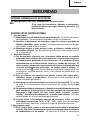
GENERAL SAFETY RULES
WARNING
: Read and understand all instructions.
Failure to follow all instructions listed below, may result in elec-
tric shock, fire and/or serious personal injury.
SAVE THESE INSTRUCTIONS
1. Work Area
(1) Keep your work area clean and well lit. Cluttered benches and dark areas
invite accidents.
(2) Do not operate power tools in explosive atmospheres, such as in the pres-
ence of flammable liquids, gases, or dust. Power tools create sparks which
may ignite the dust or fumes.
(3) Keep bystanders, children, and visitors away while operating a power tool.
Distractions can cause you to lose control.
2. Electrical Safety
(1) Double Insulated tools are equipped with a polarized plug (one blade is wider
than the other.) This plug will fit in a polarized outlet only one way. If the
plug does not fit fully in the outlet, reverse the plug. If it still does not fit,
contact a qualified electrician to install a polarized outlet. Do not change the
plug in any way. Double Insulation
eliminates the need for the three wire
grounded power cord and grounded power supply system.
(2) Avoid body contact with grounded surfaces such as pipes, radiators, ranges
and refrigerators. There is an increased risk of electric shock if your body is
grounded.
(3) Don’t expose power tools to rain or wet conditions. Water entering a power
tool will increase the risk of electric shock.
(4) Do not abuse the cord. Never use the cord to carry the tools or pull the plug
from a receptacle. Keep cord away from heat, oil, sharp edges or moving
parts. Replace damaged cords immediately. Damaged cords increase the
risk of electric shock.
(5) When operating a power tool outside, use an outdoor extension cord marked
“W-A” or “W”. These cords are rated for outdoor use and reduce the risk of
electric shock.
3. Personal Safety
(1) Stay alert, watch what you are doing and use common sense when operat-
ing a power tool. Do not use tool while tired or under the influence of drugs,
alcohol, or medication. A moment of inattention while operating power tools
may result in serious personal injury.

5
English
(2) Dress properly. Do not wear loose clothing or jewelry. Contain long hair.
Keep your hair, clothing, and gloves away from moving parts. Loose clothes,
jewelry, or long hair can be caught in moving parts.
(3) Avoid accidental starting. Be sure switch is off before plugging in. Carrying
tools with your finger on the switch or plugging in tools that have the switch
on invites accidents.
(4) Remove adjusting keys or wrenches before turning the tool on. A wrench or
a key that is left attached to a rotating part of the tool may result in personal
injury.
(5) Do not overreach. Keep proper footing and balance at all times. Proper foot-
ing and balance enables better control of the tool in unexpected situations.
(6) Use safety equipment. Always wear protective grasses. Dust mask, non-
skid safety shoes, hard hat, or ear plugs must be used for appropriate condi-
tions.
4. Tool Use and Care
(1) Use clamps or other practical way to secure and support the workpiece to a
stable platform. Holding the work by hand or against your body is unstable
and may lead to lose of control.
(2) Do not force tool. Use the correct tool for your application. The correct tool
will do the job better and safer at the rate for which it is designed.
(3) Do not use tool if switch does not turn it on or off. Any tool that cannot be
controlled with the switch is dangerous and must be repaired.
(4) Disconnect the plug form the power source before making any adjustments,
changing accessories, or storing the tool. Such preventive safety measures
reduce the risk of starting the tool accidentally.
(5) Store idle tools out of reach of children and other untrained persons. Tools
are dangerous in the hand of untrained users.
(6) Maintain tools with care. Keep cutting tools sharp and clean. Properly main-
tained tools, with sharp cutting edges are less likely to bind and are easier to
control.
(7) Check for misalignment or binding of moving parts, breakage of parts, and
any other condition that may affect the tools operation. If damaged, have
the tool serviced before using. Many accidents are caused by poorly main-
tained tools.
(8) Use only accessories that are recommended by the manufacturer for your
model. Accessories that may be suitable for one tool, may become hazard-
ous when used on another tool.
5. Service
(1) Tool service must be performed only by qualified repair personnel. Service
or maintenance performed by unqualified personnel could result in a risk of
injury.

6
English
(2) When servicing a tool, use only identical replacement parts. Follow instruc-
tions in the Maintenance section of this manual. Use of unauthorized parts
or failure to follow Maintenance Instruction may create a risk of electric shock
or injury.
6. Never touch moving parts.
Never place your hands, fingers or other body parts near the tool’s moving parts.
7. Never operate without all guards in place.
Never operate this tool without all guards or safety features in place and in proper
working order. If maintenance or servicing requires the removal of a guard or
safety feature, be sure to replace the guard or safety feature before resuming
operation of the tool.
8. Use right tool.
Don’t force small tool or attachment to do the job of a heavy-duty tool.
Don’t use tool for purpose not intended — for example — don’t use circular saw
for cutting tree limbs or logs.
9. Never use a power tool for applications other than those specified.
Never use a power tool for applications other than those specified in the Instruc-
tion Manual.
10. Handle tool correctly.
Operate the tool according to the instructions provided herein. Do not drop or
throw the tool. Never allow the tool to be operated by children, individuals unfa-
miliar with its operation or unauthorized personnel.
11. Keep all screws, bolts and covers tightly in place.
Keep all screws, bolts, and plates tightly mounted. Check their condition peri-
odically.
12. Do not use power tools if the plastic housing or handle is cracked.
Cracks in the tool’s housing or handle can lead to electric shock. Such tools
should not be used until repaired.
13. Blades and accessories must be securely mounted to the tool.
Prevent potential injuries to yourself or others. Blades, cutting implements and
accessories which have been mounted to the tool should be secure and tight.
14. Keep motor air vent clean.
The tool’s motor air vent must be kept clean so that air can freely flow at all
times. Check for dust build-up frequently.
15. Operate power tools at the rated voltage.
Operate the power tool at voltages specified on its nameplate.
If using the power tool at a higher voltage than the rated voltage, it will result in
abnormally fast motor revolution and may damage the unit and the motor may
burn out.
16. Never use a tool which is defective or operating abnormally.
If the tool appears to be operating unusually, making strange noises, or other-
wise appears defective, stop using it immediately and arrange for repairs by a
Hitachi authorized service center.

7
English
17. Never leave tool running unattended. Turn power off.
Don’t leave tool until it comes to a complete stop.
18. Carefully handle power tools.
Should a power tool be dropped or struck against hard materials inadvertently,
it may be deformed, cracked, or damaged.
19. Do not wipe plastic parts with solvent.
Solvents such as gasolie, thinner, benzine, carbon tetrachloride, and alcohol may
damage and crack plastic parts. Do not wipe them with such solvents.
Wipe plastic parts with a soft cloth lightly dampened with soapy water and dry
thoroughly.
SPECIFIC SAFETY RULES AND SYMBOLS
1. Hold tools by insulated gripping surfaces when performing an operation where
the cutting tool may contact hidden wiring or its own cord. Contact with a “live”
wire will make exposed metal parts of the tool “live” and shock the operator.
2. Wear ear plugs when using the tool for extended periods. Prolonged exposure
to high intensity noise can cause hearing loss.
3. NEVER touch the tool bit with bare hands after operation.
4. NEVER wear gloves made of stuff liable to roll up such as cotton, wool, cloth or
string, etc.
5. ALWAYS attach the side handle and securely grip the Rotary Hammer.
6. ALWAYS be careful with buried object such as an underground wiring.
Touching these active wiring or electric cable with this tool, you may receive an
electric shock.
Comfirm if there are any buried object such as electric cable within the wall,
floor or ceiling where you are going to operate here after.
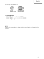
7. Definitions for symbols used on this tool
V ... volts
Hz ... hertz
A ... amperes
n
o ... no load speed
W ... watt
... Class II Consruction
- - -/min ... revolutions per minute

8
English
DOUBLE INSULATION FOR SAFER OPERATION
To ensure safer operation of this power tool, HITACHI has adopted a double insula-
tion design. “Double insulation” means that two physically separated insulation
systems have been used to insulate the electrically conductive materials connected
to the power supply from the outer frame handled by the operator. Therefore, either
the symbol “
” or the words and “Double insulation” appear on the power tool or
on the nameplate.
Although this system has no external grounding, you must still follow the normal
electrical safety precautions given in this Instruction Manual, including not using
the power tool in wet environments.
To keep the double insulation system effective, follow these precautions:
䡬 Only HITACHI AUTHORIZED SERVICE CENTER should disassemble or assemble
this power tool, and only genuine HITACHI replacement parts should be in-
stalled.
䡬 Clean the exterior of the power tool only with a soft cloth moistened with soapy
water, and dry thoroughly.
Never use solvents, gasoline or thinners on plastic components; otherwise the
plastic may dissolve.
SAVE THESE INSTRUCTIONS
AND
MAKE THEM AVAILABLE TO
OTHER USERS OF THIS TOOL!

9
English
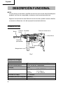
Fig. 1
SPECIFICATIONS
Motor Single-Phase, Series Commutator Motor
Power Source Single-Phase, 115V 60Hz
Current 5.7A
Capacity Concrete: 1/8" ~ 15/16" (3.4mm ~ 24mm)
Steel: 1/2" (13mm)
Wood: 1-1/4" (32mm)
No-Load Speed 0 – 1050/min.
Full-load Impact Rate 4400/min.
Weight 5.1 lbs (2.3 kg)
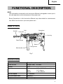
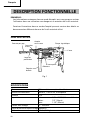
FUNCTIONAL DESCRIPTION
NOTE:
The information contained in this Instruction Manual is designed to assist you in
the safe operation and maintenance of the power tool.
Some illustrations in this Instruction Manual may show details or attachments
that differ from those on your own power tool.
NAME OF PARTS
Housing
Nameplate
Drill Bit
Front Cap
Grip
Depth Gauge
Side Handle
Lever
Switch
Change Lever

10
English
ASSEMBLY AND OPERATION
APPLICATIONS
Rotation and striking function
䡬 Drilling anchor holes
䡬 Drilling holes in concrete
䡬 Drilling holes in tile
Rotation only function
䡬 Drilling in steel or wood (with optional accessories).
䡬 Tightening machine screws, wood screws (with optional accessories).
PRIOR TO OPERATION
1. Power source
Ensure that the power source to be utilized conforms to the power source re-
quirements specified on the product nameplate.
2. Power switch
Ensure that the switch is in the OFF position. If the plug is connected to a recep-
tacle while the switch is in the ON position, the power tool will start operating
immediately and can cause serious injury.
3. Extension cord
When the work area is far away from the power source, use an extension cord of
sufficient thickness and rated capacity. The extension cord should be kept as
short as practicable.
WARNING: Damaged cord must be replaced or repaired.
4. Check the receptacle
If the receptacle only loosely accepts the plug, the receptacle must be repaired.
Contact a licensed electrician to make appropriate repairs.
If such a fautly receptacle is used, it may cause overheating, resulting in a seri-
ous hazard.
5. Confirming condition of the environment:
Confirm that the work site is placed under appropriate conditions conforming to
prescribed precautions.

11
English
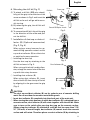
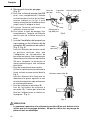
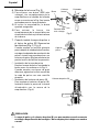
Fig. 3
Dust Cup
Dust Collector (B)
Drill bit
Part of SDS-plus shank
Grip
Front cap
Fig. 2
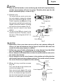
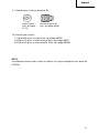
6. Mounting the drill bit (Fig. 2)
(1) To attach a drill bit (SDS-plus shank),
fully pull the grip in the direction of the
arrow as shown in Fig. 2 and insert the
drill bit as far as it will go while manu-
ally turning.
(2) By releasing the grip, the drill bit will
be secured.
(3) To remove the drill bit, fully pull the grip
in the direction of the arrow and pull
out the drill bit.
7. Installation of dust cup or dust col-
lector (B) (Optional accessories)
(Fig. 3, Fig. 4)
When using a rotary hammer for up-
ward drilling operations attach a dust
cup or dust collector (B) to collect dust
or particles for easy operation.
䡬 Installing the dust cup
Use the dust cup by attaching to the
drill bit a shown in Fig. 3.
When using a bit which has big diam-
eter, enlarge the center hole of the dust
cup with this rotary hammer.
䡬 Installing dust collector (B)
When using dust collector (B), insert
dust collector (B) from the tip of the bit
by aligning it to the groove on the grip
(Fig. 4)
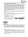
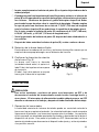
CAUTION:
䡬 The dust cup and dust collector (B) are for exclusive use of concrete drilling
work. Do not use them for wood or metal drilling work.
䡬 Insert dust collector (B) completely into the chuck part of the main unit.
䡬 When turning the rotary hammer on while dust collector (B) is detached from a
concrete surface, dust collector (B) will rotate together with the drill bit. Make
sure to turn on the switch after pressing dust cup on the concrete surface.
(When using dust collector (B) attached to a drill bit that has more than 7-15/
32" (190 mm) of overall length, dust collector (B) cannot touch the concrete
surface and will rotate. Therefore please use dust collector (B) by attaching to
Fig. 4

12
English
drill bits which have 6-17/32" (166 mm), 6-19/64" (160 mm) and 4-21/64" (110
mm) overall length.
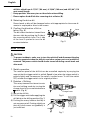
䡬 Dump particles after every two or three holes when drilling.
䡬 Please replace the drill bit after removing dust collector (B).
8. Selecting the driver bit
Screw heads or bits will be damaged unless a bit appropriate for the screw di-
ameter is employed to drive in the screws.
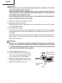
9. Confirm the direction of bit ro-
tation (Fig. 5)
The bit rotates clockwise (viewed from
the rear side) by pushing the R-side of
the reversing switch lever. The L-side
of the lever is pushed to turn the bit
counterclockwise.
HOW TO USE
CAUTION:
䡬 To prevent accidents, make sure to turn the switch off and disconnect the plug
from the receptacle when the drill pits and other various parts are installed or
removed. The power switch should also be turned off during a work break and
after work.
1. Switch operation
The rotation speed of the drill bit can be controlled steplessly by varying the
amount that the trigger switch is pulled. Speed is low when the trigger switch is
pulled slightly and increases as the switch is pulled more. To turn the switch
OFF, release the trigger switch to its original position.
2. Rotation + Striking
This rotary hammer can be set to rota-
tion and striking mode by turning the
change lever fully counterclockwise to
mark. (Fig. 6)
(1) Mount the drill bit.
(2) Pull the trigger switch after applying the
drill bit tip to the drilling position (Fig. 7)
(3) Pushing the rotary hammer forcibly is
not necessary at all. Pushing slightly so
that drill dust comes out gradually is
just sufficient.
Lever
Fig. 5
Fig. 6
Change Lever
Fig. 7

13
English
CAUTION:
䡬 When the drill bit touches an iron reinforcing rod, the bit will stop immediately
and the rotary hammer will react to revolve. Therefore please grip the side
handle and handle tightly as shown in Fig. 7.
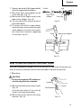
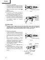
3. Rotation only
The rotary hammer can be set to rota-
tion only mode by rotating the change
lever fully clockwise to
mark. (Fig. 8)
To drill a wood or metal material using
the separately sold drill chuck and chuck
adaptor, proceed as follows. Installing
drill chuck and chuck adaptor (Fig. 9):
(1) Attach the drill chuck to the chuck
adaptor.
(2) The part of the SDS-plus shank is the
same as the drill bit. Therefore, refer to
the item of “Mounting the drill bit” for
attaching it.
CAUTION:
䡬 Application of force more than necessary will not only reducing drilling effi-
ciency at all, but will deteriorate the tip edge of the drill bit and reduce the
service life of the rotary hammer in addition.
䡬 Drill bit may snap off while withdrawing the rotary hammer from the drilled
hole. For withdrawing, it is important to use a pushing motion.
䡬 Do not attempt to drill anchor holes or holes in concrete with the main unit in
the rotation only function.
䡬 Do not attempt to use the rotary hammer in the rotation and striking function
with the drill chuck and chuck adaptor attached. This would seriously shorten
the service life of every components of the machine.
4. When driving machine screws
(Fig. 10)
First, insert the bit into the socket in the
end of chuck adaptor (D).
Next, mount chuck adaptor (D) on the
main unit using procedures described
in 5 (1), (2), (3), put the tip of the bit in
the slots in the head of the screw, grasp
the main unit and tighten the screw.
Bit
Socket
Chuck Adaptor (D)
Front Cap
Grip
Fig. 10
Change lever
Fig. 8
Chuck Adaptor
Drill Chuck
Part of SDS-plus
shank
Front Cap
Grip
Fig. 9

14
English
CAUTION:
䡬 Exercise care not to excessively prolong driving time, otherwise, the screws
may be damaged by excessive force.
䡬 Apply the rotary hammer perpendicularly to the screw head when driving a
screw; otherwise, the screw head or bit will be damaged, or driving force will
not be fully transferred to the screw.
䡬 Do not attempt to use the rotary hammer in the rotation and striking function
with chuck adaptor (D) and bit attached.
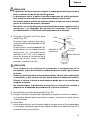
5. When driving wood screws (Fig. 10)
(1) Selecting a suitable driver bit
Employ phillips screws, if possible, since the driver bit easily slips off the heads
of slotted-head screws.
(2) Driving in wood screws
䡬 Prior to driving in wood screws, make pilot holes suitable for them in the wooden
board. Apply the bit to the screw head grooves and gently drive the screws into
the holes.
䡬 After rotating the rotary hammer at low speed for a while until a wood screw in
partly driven into the wood, squeeze the trigger more strongly to obtain the
optimum driving force.
CAUTION:
䡬 Exercise care in preparing a pilot hole suitable for the wood screw taking the
hardness of the wood into consideration. Should the hole be excessively small
or shallow, requiring much power to drive the screw into it, the thread of the
wood screw may sometimes be damaged.
6. Using depth gauge (Fig. 11)
(1) Loosen the knob on the side handle,
and insert the depth gauge into the
mounting hole on the side handle.
(2) Adjust the depth gauge position ac-
cording to the depth of the hole and
tighten the knob bolt securely.
Mounting Hole
Depth Gauge
Knob on Side
Handle
Fig. 11

15
English
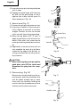
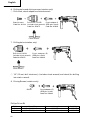
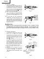
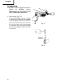
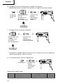
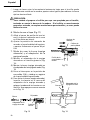
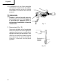
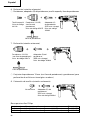
7. How to use the drill bit (taper shank)
and the taper shank adaptor.
(1) Mount the taper shank adaptor to the
rotary hammer. (Fig. 12)
(2) Mount the drill bit (taper shank) to the
taper shank adaptor. (Fig. 12)
(3) Turn the switch ON, and drill a hole in
prescribed depth.
(4) To remove the drill bit (taper shank),
insert the cotter into the slot of the taper
shank adaptor and strike the head of
the cotter with a hammer supporting
on the rests. (Fig. 13)
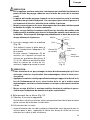
HOW TO USE THE CORE BIT (FOR LIGHT LOAD)
When boring penetrating large hole use the core bit (for light load). At that time use
with the center pin and the core bit shank provided as optional accessories.
1. Mounting
CAUTION:
䡬 Be sure to turn power OFF and discon-
nect the plug from the receptacle.
(1) Mount the core bit to the core bit shank.
(Fig. 14)
Lubricate the thread of the core bit
shank to facilitate disassembly.
(2) Mount the core bit shank to the rotary
hammer. (Fig. 15)
Fig. 12
Drill Bit
Taper shank
Adaptor
Front Cap
Grip
Cotter
Rests
Taper Snank Adaptor
Fig. 13
Fig. 14
Core Bit
Thread
Core Bit Shank

16
English
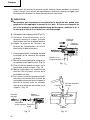
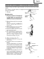
(3) Insert the center pin into the guide plate
until it stops.
(4) Engage the guide plate with the core
bit, and turn the guide plate to left or
right so that it does not fall even if it
faces downward. (Fig. 16)
2. How to bore (Fig. 17)
(1) Connect the plug to the power source.
(2) A spring is installed in the center pin.
Push it lightly to the wall or the floor
straight. Connect all over the surface
of the core bit tip and start operating.
(3) When boring about 3/16" (5 mm) in
depth the position of the hole will es-
tablish. Bore after that removing the
center pin and the guide plate from core
bit.
(4) Application of excessive force will not
only expedite the work, but will dete-
riorate the tip edge of the drill bit, re-
sulting in reduced service life of the ro-
tary hammer.
CAUTION:
䡬 When removing the center pin and the
guide plate, turn OFF the switch and
disconnect the plug form the recep-
tacle.
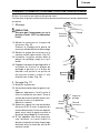
3. Dismounting. (Fig. 18)
Remove the core bit shank from the ro-
tary hammer and strike the head of the
core bit shank strongly two or three
times with the hammer holding the
core bit, then the thread becomes loose
and the core bit can be removed.
Fig. 15
Fig. 17
Fig. 16
Core Bit
Core Bit Tip
Guide Plate
Center Pin
Fig. 18
Core Bit shank

17
English
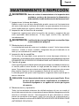
MAINTENANCE AND INSPECTION
WARNING: Be sure to switch power OFF and disconnect the plug from the
receptacle during maintenance and inspection.
1. Inspecting the drill bits
Since use of a dull tool will cause motor malfunctioning and degraded efficiency,
replace the drill bit with a new one or resharpening without delay when abra-
sion is noted.
2. Inspecting the mounting screws
Regularly inspect all mounting screws and ensure that they are properly tight-
ened. Should any of the screws be loosened, retighten them immediately.
WARNING: Using this rotary hammer with loosen screws is extremely dan-
gerous.
3. Maintenance of the motor
The motor unit winding is the very “heart” of the power tool. Exercise due care
to ensure the winding does not become damaged and/or wet with oil or water.
4. Inspecting the carbon brushes
For your continued safety and electrical shock protection, carbon brush inspec-
tion and replacement on this tool should ONLY be performed by a HITACHI AU-
THORIZED SERVICE CENTER.
5. How to replace grease
Low viscosity grease is applied to this rotary hammer so that it can be used for
a long period without replacing the grease. Please contact the nearest service
center for grease replacement when any grease is leaking from loosened screw.
Further use of the rotary hammer despite the grease shortage causes seizure to
reduce the service life.
CAUTION: A specific grease is used with this machine, therefore, the normal
performance of the machine may be badly affected by use of other
grease. Please be sure to let one of our service agents undertake
replacement of the grease.
6. Service and repairs
All quality power tools will eventually require servicing or replacement of parts
because of wear from normal use. To assure that only authorized replacement
parts will be used, all service and repairs must be performed by a HITACHI AU-
THORIZED SERVICE CENTER, ONLY.

18
English
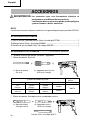
ACCESSORIES
WARNING: Accessories for this power tool are mentioned in this Instruction
Manual.
The use of any other attachment or accessory can be dangerous
and could cause injury or mechanical damage.
NOTE:
Accessories are subject to change without any obligation on the part of the HITACHI.
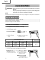
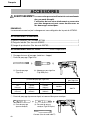
STANDARD ACCESSORIES
(1)Case (Molded plastic) (Code No. 307786) ...............................................................1
(2)Side Handle (Code No. 303659) ...............................................................................1
(3)Depth Gauge (Code No. 303709) .............................................................................1
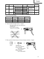
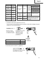
1. Drilling anchor holes (Rotation + Striking)
䡬 Drill Bit (Slender shaft)
(1) Drill Bit (Slender
Shaft)
(2) Adaptor for slender shaft
(SDS-plus shank)
(1) Drill Bit (Slender Shaft)
(2) Adaptor for
Slender Shaft
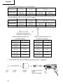
Outer diameter Effective Length Overall Length Code No. Code No.
1/8" 1-25/32" 3-35/64"
306369
(3.4mm) (45mm) (90mm)
306370
9/64" 1-25/32" 3-35/64"
306368
(3.5mm) (45mm) (90mm)
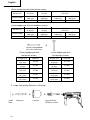
䡬 Drill Bit (Taper shank) and taper shank adaptor
(1) Drill Bit (Taper Shank)
(2) Taper Shank Adaptor
(SDS-plus shank)
Cotter (Code No. 944477)
OPTIONAL ACCESSORIES...........sold separately

19
English
Taper mode Code No. Applicable drill bit
7/16" (11 mm)
31/64" (12.3 mm)
303617
1/2" (12.7 mm)
9/16" (14.3 mm)
73/128" (14.5 mm)
11/16" (17.5 mm)
303618 27/32" (21.5 mm)
A-taper 303619
B-taper 303620
External dia. Code No.
7/16"
944460
(11 mm)
31/64"
944461
(12.3 mm)
1/2"
993038
(12.7 mm)
9/16"
944462
(14.3 mm)
73/128"
944500
(14.5 mm)
11/16"
944463
(17.5 mm)
27/32"
944464
(21.5 mm)
Morse taper
(No. 1)
Drill bit
(Taper
shank)
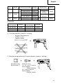
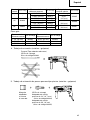
䡬 1/2" (13 mm) Hammer Drill chuck and Chuck wrench
For drilling operations when using a straight shank bit for impact driling with a
rotary hammer
1/2" (13 mm) Hammer Drill
Chuck (SDS-plus shank)
(includes Chuck wrench)
Chuck wrench
Name Code No.
1/2" (13 mm) Hammer Drill Chuck 303332
Chuck wrench 303334
Rubber Cap 303335
2. Knock-in anchor (Rotation + Striking)
Anchor Setter (for anchor setting)
(SDS-plus shank)
Impact Drill
Application
Straight shank Bit
Taper shank adaptor formed A-
taper or B-taper is provided as an
optional accessory, but drill bit for
it is not provided.
Morse taper
(No. 2)
Drill bit
(Taper
shank)

20
English
<Outer wedge type with the female screw>
Anchor size
W 1/4" W 5/16" W 3/8"
(6.3 mm) (8 mm) (9.5 mm)
Overall Length
10-15/64" 10-15/64" 6-19/64" 10-15/64"
(260 mm) (260 mm) (160 mm) (260 mm)
Code No. 302976 302975 303621 302974
<Inner wedge type with the headless screw>
Anchor size
W 1/4" W 5/16" W 3/8"
(6.3 mm) (8 mm) (9.5 mm)
Overall Length
10-15/64" 10-15/64" 6-19/64" 10-15/64"
(260 mm) (260 mm) (160 mm) (260 mm)
Code No. 302979 302978 303622 302977
Anchor setting adaptor
(for manual hammer)
<Outer wedge type with
the female screw>
Anchor size Code No.
W1/4"
971794
(6.3 mm)
W5/16"
971795
(8 mm)
W3/8"
971796
(9.5 mm)
W1/2"
971797
(12.7 mm)
W5/8"
971798
(15.9 mm)
<Inner wedge type with
the headless screw>
Anchor size Code No.
W1/4"
971799
(6.3 mm)
W5/16"
971800
(8 mm)
W3/8"
971801
(9.5 mm)
W1/2"
971802
(12.7 mm)
W5/8"
971803
(15.9 mm)
3. Large hole boring (Rotation + Striking)
Guide
Plate
Center pin Core Bit
Core bit Shank
(SDS-plus shank)
La page charge ...
La page charge ...
La page charge ...
La page charge ...
La page charge ...
La page charge ...
La page charge ...
La page charge ...
La page charge ...
La page charge ...
La page charge ...
La page charge ...
La page charge ...
La page charge ...
La page charge ...
La page charge ...
La page charge ...
La page charge ...
La page charge ...
La page charge ...
La page charge ...
La page charge ...
La page charge ...
La page charge ...
La page charge ...
La page charge ...
La page charge ...
La page charge ...
La page charge ...
La page charge ...
La page charge ...
La page charge ...
La page charge ...
La page charge ...
La page charge ...
La page charge ...
La page charge ...
La page charge ...
La page charge ...
La page charge ...
La page charge ...
La page charge ...
La page charge ...
La page charge ...
La page charge ...
La page charge ...
La page charge ...
La page charge ...
La page charge ...
La page charge ...
La page charge ...
La page charge ...
-
 1
1
-
 2
2
-
 3
3
-
 4
4
-
 5
5
-
 6
6
-
 7
7
-
 8
8
-
 9
9
-
 10
10
-
 11
11
-
 12
12
-
 13
13
-
 14
14
-
 15
15
-
 16
16
-
 17
17
-
 18
18
-
 19
19
-
 20
20
-
 21
21
-
 22
22
-
 23
23
-
 24
24
-
 25
25
-
 26
26
-
 27
27
-
 28
28
-
 29
29
-
 30
30
-
 31
31
-
 32
32
-
 33
33
-
 34
34
-
 35
35
-
 36
36
-
 37
37
-
 38
38
-
 39
39
-
 40
40
-
 41
41
-
 42
42
-
 43
43
-
 44
44
-
 45
45
-
 46
46
-
 47
47
-
 48
48
-
 49
49
-
 50
50
-
 51
51
-
 52
52
-
 53
53
-
 54
54
-
 55
55
-
 56
56
-
 57
57
-
 58
58
-
 59
59
-
 60
60
-
 61
61
-
 62
62
-
 63
63
-
 64
64
-
 65
65
-
 66
66
-
 67
67
-
 68
68
-
 69
69
-
 70
70
-
 71
71
-
 72
72


Hitachi DH24PB Manuel utilisateur
- Catégorie
- Outils électroportatifs
- Taper
- Manuel utilisateur
- Ce manuel convient également à
dans d''autres langues
- English: Hitachi DH24PB User manual
- español: Hitachi DH24PB Manual de usuario
Documents connexes
-
Hitachi DH24PB3 Manuel utilisateur
-
-
-
-
-
Hitachi DH 24 PF Manuel utilisateur
-
-
-
-
