ROSIERES PG90 Le manuel du propriétaire
- Catégorie
- Fours
- Taper
- Le manuel du propriétaire
Ce manuel convient également à

mod.
GB
INSTRUCTIONS BOOKLET
FR
NOTICE DEMPLOI ET ENTRETIEN

DEAR CUSTOMER,
Carefully read these instructions before using the appliance and
keep them for future consultation.
Keep potentially hazardous packaging (plastic bags, polystyrene
etc.) out of the reach of children.
ENVIRONMENT PROTECTION
Packing disposal
Sort packing into different materials (cardboard, polystyrene
etc.) and dispose of them in accordance with local waste
disposal laws.
This appliance complies with the following European Directives:
- 2006/95/EEC regarding "Low Voltage".
- 2004/108/EEC regarding "Electromagnetic Disturbances".
- 90/396/EEC regarding Gas appliances
- 89/109/EEC regarding "Materials in contact with food"
- Moreover the above mentioned Directives comply with Directive
93/68/EEC.
This appliance must be installed in accordance with the regulations
in force and must only be used in well ventilated rooms. Consult the
instructions booklet before installing and using the appliance.
- This household appliance has been designed for cooking and it must
therefore be used for this purpose only.
ATTENTION:
The use of a gas cooking appliance results in the production of heat
and moisture in the room in which it is installed. Ensure that the kitchen
is well ventilated : keep natural ventilation holes open or install a
mechanical ventilation device (mechanical extractor hood).
Prolonged intensive use of the appliance may call for additional
ventilation, for example opening of a window, or more effective
ventilation, for example increasing the level of mechanical ventilation
where present.
Prior to installation, ensure that the local distribution conditions (nature
of the gas and gas pressure) and the adjustment of the appliance are
compatible.
- Before using the appliance, do not forget to remove the plastic films
protecting some parts of the appliance (facia-panel, parts in stainless
steel, etc.)
- Do not use the appliance as a space heater.
- When the appliance is not in use, we recommend
to disconnect
the current and to close the gas general tap.
IN CASE OF FIRE:
In case of fire, close
immediately the main valve of the gas pipe
line, disconnect current and never pour water on firing oil in any
case.
Do not store flammable products or aerosol containers near the
burners, and do not vaporize them near lighted burners.
FOR YOUR SAFETY AND THE ONE OF YOUR CHILDREN.
Do not store items that are attractive to children above or near the
appliance.
Keep children well away from the appliance: do not forget that some
parts of the appliance or of the pans become very hot and dangerous
during use, and also for all the time necessary to cool down.
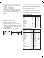
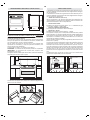
LOWER DRAWER (Fig. A).
You must not place inflammable materials or plastic utensils in the
warming cabinet (placed below the oven).
In order to avoid any unintentional fall down, pan handles should
be turned to the back of the cooker, not out to the room or over
adjacent burners.
When cooking, do not use clothes with large flaving and flammable
sleeves; in case of firing you can suffer very serious harms.
The appliance must not be used be people (including children) with
limited physical, sensory or mental abilities, or without experience
or expertise, unless they have received instructions for using it from
those responsible for their safety. Young children should be supervised
to ensure they not play with the appliance.
WARNING - OVEN:
When the oven or the grill are in use, accessible parts can become
very hot; it is necessary to keep children well away from the
appliance.
- Never cook food on the lower wall of the oven.
- In case of careless use, in proximity of the oven door hinges, there
is hurt danger.
- Do not let children sit down or play with the oven door. Do not use
the drop down door as a stool to reach above cabinets.
Fig. A
GB
2
GENERAL INFORMATION
RECCOMANDATIONS AND PRECAUTIONS
This appliance is marked according to the European directive
2002/96/EC on Waste Electrical and Electronic Equipment (WEEE).By
ensuring this product is disposed of correctly, you will help prevent
potential negative consequences for the environment and human
health, which could otherwise be caused by inappropriate waste
handling of this product.
The symbol on the product, or on the documents accompanying
the product, indicates that this appliance may not be treated as
household waste. Instead it shall be handed over to the applicable
collection point for the recycling of electrical and electronic equipment.
Disposal must be carried out in accordance with local environmental
regulations for waste disposal.For more detailed information about
treatment, recovery and recycling of this product, please contact your
local city office, your household waste disposal service or the shop
where you purchased the product.
CUSTOMER ASSISTANCE SERVICE
If you cannot identify the cause of the operating anomaly, switch off
the appliance (do not subject it to rought treatment) and contact the
Assistance Service.
PRODUCT SERIAL NUMBER. Where can i find it?
It is important you to inform the Assistance Service of your product
code and its serial number; this can be found on the guarantee
certificate or on the data plate located on the appliance (fig. A ).
It will help to avoid wasted journerys to technicians, thereby (and most
significantly) saving the corresponding callout charges.

USING GAS BURNERS
The following symbols are on the control panel next to each knob:
- Black circle gas off
- Large flame maximum setting
- Small flame minimum setting
The minimum position is at the end of the anti-clockwise rotation of
the knob. All operation positions must be chosen between the positions
of max. and min., never choose them between max. and off.
The first time the oven is used, it may give off acrid smells, caused
by the first heating of isolating panels glue surrounding the oven (it
is necessary to heat up the oven at the maximum temperature
for about 30-40 minutes with closed door).
It is something normal, and in case it will occur, wait for the smoke
to stop before introducing the food into the oven.
The oven is fitted with: a rod shelf for cooking food contained in oven
dishes or placed directly on the rod shelf itself, a drip-tray for cooking
sweets, biscuits, pizzas, etc., or for collecting juices and fats from
food cooked directly on the rod shelf.
Note: The following tables give the main points for cooking some of
the most important dishes. The cooking times recommended in these
tables are approximate. After a few tries, we are sure that you will be
able to adjust the times to get the results you want.
Fan oven cooking table TAB. C.
ENERGY SAVING TIPS
The diameter of the pan bottom should be the same as that of the
burner. The burner flame must never come out from the pans
diameter.
Use flat-bottomed pans only.
Whenever possible, keep a lid on the pan while cooking.
You will not need as much heat.
Cook vegetables, potatoes, etc. with as little water as possible to
reduce cooking times.
Conventional cooking table TAB.B
3
GB
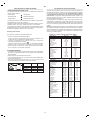
Dish Temp. °C. Minutes Weight kg.
Firs courses
Lasagne 200-220 20-25 0,5
Oven pasta 200-220 25-30 0,5
Creole rice 200-230 20-25 0,5
Pizza 210-230 30-45 0,5
Meat
Roast veal 160-180 65-90 1-1,2
Roast pork 160-170 70-100 1-1,2
Roast ox 170-190 40-60 1-1,2
Roast beef joint 170-180 65-90 1-1,2
Roast fillet beef (rare) 180-190 40-45 1-1,5
Roast lamb 140-160 100-130 1,5
Roast chicken 180 70-90 1-1,2
Roast duck 170-180 100-160 1,5-2
Roast goose 160-180 120-160 3-3,5
Roast turkey 160-170 160-240 5 approx.
Roast rabbit 160-170 80-100 2 approx.
Roast hare 170-180 30-50 2 approx.
Fish 160-180 acc. to weight
Sweets (pastries)
Fruit flan 180-200 40-50
Plain sandwich cake 160-180 35-45
Sponge sandwich cake 200-220 40-45
Sponge cake 200-230 25-35
Currant cake 230-250 30-40
Buns 170-180 40-60
Strûdel 160 25-35
Cream slices 180-200 20-30
Apple fritters 180-200 18-25
Sponge finger pudding 170-180 30-40
Sponge finder biscuits 150-180 50-60
Toasted sandwiches 230-250 7
Bread 200-220 40
Dish Temp. °C. Minutes
Fish 180-240 acc. to size
Meat
Roast ox 250 30 per kg.
Roast veal 200-220 30 per kg.
Chicken 200-240 50 about
Duck and goose 220 acc. to weight
Leg of mutton 250 30 per kg.
Roast pork 250 60 per kg.
Soufflets 200 60 per kg.
Sweets (pastries)
Tea-cake 160 50-60
Sponge finger 160 30-50
Shortcrust pastry 200 15
Puff pastry 250 15
Fruit flan 200-220 30
Meringues 100 60
Quiches, etc. 220 30
4 quarters 120-140 60
Buns 160-180 45
BURNERS PANS
Ø min. Ø max
RAPIDE 180 mm 220 mm
SEMIRAPIDE 120 mm 200 mm
AUXILIARY 80 mm 160 mm
TRIPLE CROWN 220 mm 260 mm
The gas burners are equipped with a thermocouple safety device to
prevent gas from leaking out. This device ensures that the gas supply
is shut off if the flame on the gas burner is extinguished while the
burner is in use.
Igniting the gas burners
Proceed as follows to light one of the burners
Turn the appropriate knob anti-clockwise to the large flame
symbol;
Press in the knob firmly to activate the automatic gas
igniter ;
Hold the knob in for around 10 seconds once the flame has
ignited to allow the thermocouple to heat up.
Then release the control knob and ensure that the gas has
ignited properly. If it has not, repeat the process.
In case there is no electric current, the burner can also be lighted
using a match.
WORK-TOP USE
USE OF THE ELECTRIC OVEN

Use of the oven
Note: ovens with separate thermostat and commutator.
When the functions are used, place the thermostat knob
between 180 ÷ 200°C as maximum temperature.
ATTENTION:
The temperature shown on the control panel corresponds to the
temperature in the oven centre only when the functions selected are
or .
When you turn the control knob to this position, the light will be on for
all the following operations.
Oven commutator knob
Depending on the type of oven, it is possible to select one of the following
functions turning the commutator knob clockwise.
The turnspit can be operated turning the knob on position .
Oven thermostat knob
To obtain an oven temperature between 60°C and MAX°C, turn the knob
clockwise.
warnings:
do not use the wire shelves on the oven levels equipped with the
telescopic runners
Do not cook foods on the bottom in the base of the oven.
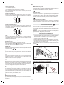
Fig. 3
Defrosting with fan
The air at ambient temperature is distributed inside the oven for
defrosting food very quickly and without proteins adulterations.
Natural convection
Both the lower and upper heating elements operate together.
This is the traditional cooking, very good for roasting joints, ideal for
biscuits, baked apples and crisping food.
You obtain very good results when cooking on a shelf adjusting the
temperature between 60 and MAX°C.
Fan oven
Both the fan and the circular heating element operate together.
The hot air adjustable between 60 and MAX°C is evenly distributed
inside the oven. This is ideal for cooking several types of food (meat,
fish) at the same time without affecting taste and smell.
It is indicated for delicate pastries.
Medium grill
It is indicated for grilling and gratinating small quantities of traditional
food.
The thermostat knob must be placed on the maximum position.
Note:
All the functions mentioned above switch the oven internal light on. A
warning light on the control panel will stay lit until the temperature is reached;
after it will light up intermittently.
Always use the oven with the oven door closed
4
GB
Air forced lower heating element
The air which is heated by the lower heating element is circulated by
the fan which distributes the heat on the food.
This function can be used to sterilize food. This function can be used
between 60 and MAX°C
Install the grid on the third shelf from the oven bottom, at about 12 cm
from the surface.
The user can change the shelves, depending on his personal whishes
and on the different food.
Geat the oven 5 minutes before introducing the food.
CAUTION: accessible parts may be hot when the grill is in use.
Young children should be kept away.
USE OF THE GRILL
USE OF THE TURNSPIT
Total grill
It is indicated for grilling and gratinating traditional food.
Turn the thermostat control knob to the 200°C position.
Fan assisted total grill
The air which is heated by the grill heating element is circulated by the
fan which distributes the heat on the food.
The fan assisted grill replaces perfectly the turnspit. You can obtain
very good results also with large quantities of poultry, sausage, red
meat. Turn the thermostat control knob to the 200°C position.
150
80
60
max
100
125
175
200
225
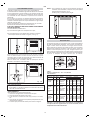
MULTIFUNCTIONAL OVEN
The oven is fitted with:
a lower heating element;
an upper heating element;
a circular heating element surrounding the fan.
N.B.: Always set the temperature on the thermostat knob before selecting
any of the functions.
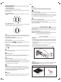
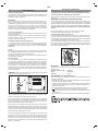
TURNSPIT
For utilization of the turnspit follow the instructions described.
- Put the food in spit L (see fig. 3), paying attention to block it within
the two forks F and to balance it, in order to avoid any unnecessary
effort in motor R.
- Put the spit on support G, after having put its opposite end into hole
P of motor R.
- Place the drip-tray with a little water under the spit.
-
when removing the spit , wear oven mitts.
L
F
R
P
G
335 mm
405 mm
AB
Oven accessories optional
A = wire shelves B = Grill pan set (2)

Setting
To set, press and release the desired function, and within 5 seconds
set the time with and buttons.
and buttons.
The + and - buttons increase or decrease the time at a speed depending
on how long the button is pressed.
Setting the time
Press any two buttons manualat the same time, and or button
to set the desired time. This deletes any previously set programme.
The contacts are switched off .
Manual use
By pressing the manual button the relay contacts switch on, the AUTO
symbol switches off and the saucepan symbol lights up.
Manual operation can only be enabled after the automatic programme
is over or it has been cancelled.
Automatic use
Press the cooking time or end time button to switch automatically from
the manual to the automatic function.
Semi-automatic use with cooking time setting
Press the cooking time button and set the desired time with or .
The AUTO and cooking time symbols light up continuously. The relay
switches on immediately. When the cooking end time corresponds to
the time of day, the relay and cooking time symbol switch off, the
sound signal rings and the AUTO symbol flashes.
Semi-automatic use with end time setting
Press the end time button. The time of day appears on the display.
Set the cooking end time with button. The AUTO and cooking time
symbols light up continuously. The relay contacts switch on. When
the cooking end time corresponds to the time of day, the relay and
the cooking time symbol switch off. When the cooking time is up, the
AUTO symbol flashes, the sound signal rings and both the relay and
the cooking time button switch off.
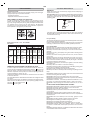
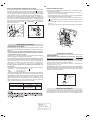
The interior glass of the oven
The interior glass of the oven door can be removed:
with the door in a semi-open position, remove the screws A and B
and the profime C
as shown in fig. 9
Use both hands to remove the glass as shown in figures 9A.
After cleaning, refit the glass by proceeding in reverse order.
Before cleaning the appliance
, disconnect the gas general tap
and unplug the appliance or disconnect power at the main circuit
breaker of the electrical system.
Do not clean the appliance surfaces when still hot.
Do not use steam cleaners to clean the oven.
IMPORTANT
Periodically check the external gas connection hole and replace
it when it shows any sign of deterioration. Do not attempt to
repair the gas hose under any cincumstances.
ENAMELLED SURFACES
Clean with a damp sponge using soap and water.
Grease can be easily removed using hot water or a specific cleansing
agent for enamelled surfaces. Do not use abrasive cleansers.
Do not leave any acid or alkaline substances (lemon juice, vinegar,
salt, etc.) on the enamel.
Clean the parts in stainless steel with specific cleansers for stainless
steel surfaces.
These detergents must be applied using a soft cloth.
GRIDS AND BURNERS
To clean the work-top burners, remove them by pulling upwards and
soak them for about 10 minutes in hot water with a little detergent.
After having cleaned and washed them, wipe them carefully.
Make sure that no burner hole is clogged.
Clean the burners once a week or more frequently if necessary.
MAKE SURE YOU HAVE ASSEMBLED THE BURNERS IN A RIGHT
WAY.
GB
5
Start programme and check
The programme starts 4 seconds after it has been set.
The programme can be checked at any time by pressing the
corresponding button.
Setting error
A setting error is made if the time of day on the clock falls within the
cooking start and end times.
To correct the setting error, change the cooking time or cooking end
time.
The relays switch off when a setting error is made.
Cancelling a setting
To cancel a setting, press the cooking time button and then press the
- button until 00 00 appears on the display.
A set programme will automatically cancel on completion.
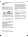
Minute timer
Cooking time
Cooking end
Manual
Subtract time
Add time
A
U
T
O
Fig. 4
Display
4-figures, 7-segments diplay for cooking times and time of day.
Cooking time and manual function = saucepan symbol
Automatic function = AUTO
Minutes counter = bell symbol
The symbols light up when the corresponding functions are selected.
LED PROGRAMMER (Fig. 4)
Features
24 hours clock with automatic programme and minutes counter.
Functions
Cooking time, cooking end time, manual position, clock,
minutes counter, times to be set up to 23 hours 59 minutes.
INSTRUCTIONS FOR USE OF CONTROL DEVICES
OVEN
Clean the enamelled parts with a damp sponge using soap and water.
Grease can be easily removed using hot water or a specific cleansing
agent for enamelled surfaces.
Do not use abrasive cleansers.
CARE AND MAINTENANCE
When the set time is up, the sound signal rings and the bell symbol
switches off.
Sound signal
The sound signal starts at the end of a programme or of the minutes
counter function and it lasts for 15 minutes.
To stop it, push any one of the functions buttons.
Automatic use with cooking time and end time setting
Press the cooking time button and select the length of the cooking
time with or button. The AUTO and cooking time symbols light
up continuously. The relay switches on. By pressing the cooking end
time button the next cooking end time appears on the display. Set the
cooking end time with button. The relay and the cooking time symbol
switch off.
The symbol lights up again when the time of day corresponds to the
cooking start time. When the cooking time is up, the AUTO symbol
flashes, the sound signal rings, the cooking time symbol and the relay
switch off.
Minutes counter
Press the minutes counter button and set the cooking time with
or button.
The bell symbol lights up when the minutes counter is operating

Removal of oven door
In-depth cleaning of the oven becomes more convenient if the door
is removed following the instructions below:
1 open the oven door completely.
2 flip the hinge hooks "A" outwards (see fig. 9B).
3 shut the oven door slowly until it reaches hooks "A", making sure
these are locked into slots "B" of the oven door, as shown in fig.
9C. Remove the glass FIg. 9A (
only for models where present).
4 Using both hands, push the oven door lightly inwards, toenable the
door hinges "C" to come away from the slots "D" (see fig. 9D) and
pull the door towards you until it is released from the oven.
After cleaning it, reposition it correctly following the abovesteps in the
reverse order and flipping hooks "A" inwardsbefore you shut the oven
door (fig. 9E).
CAUTION:
Do not use rough or abrasive materials or sharp metal scrapers
to clean the glass doors of the oven since they may scratch the
surface and cause the glass to break.
GB
6
WARNINGS
Do not use the oven door handle to move the appliance, such as to
remove it from the packaging.
The appliance is in class 1 or class 2 subclass 1.
IMPORTANT: The coating of the furniture must be able to withstand
high temperatures (min. 90°C).
CAUTION: The cooker must not be placed on a pedestal.
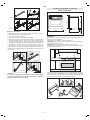
If the appliance is to be installed near units, leave the minimum gaps
specified in the table below.
The cooker is fitted with 4 legs for an eventual alignment in height
with the furniture. To assemble them, it is necessary to raise the
cooker and to screw the four legs into the suitable threadings placed
on the corners on the bottom of the appliance ( fig 8).
min.100 mm
min. 50 mm
min. 650 mm
min. 400 mm
"0" mm "0" mm
min. 50 mm
Fig. 8
OVERALL DIMENSIONS
INSTRUCTIONS DESTINED TO THE USER
895
600
120/170
750
810
Fig. 9A
Fig. 9
B
A
C
AA
A
B
A
C
D
A
Fig. 9C
Fig. 9B
Fig. 9D
Fig. 9E
OK
NO
1
2

WARNING: connect the gas to the oven's gas supply line using the
supplied connector (A) (see figure 12)
This appliance shall be installed in accordance whit the regulations in
force and only in a well-ventilated space. Read the instructions before
installing or using this appliance.
IMPORTANT
We recommend to check wether the appliance has been foreseen for the
kind of gas distributed. Conversion for use other gases must only be
undertaken by a qualified person. For information for use on other gases
contact your local Service Centre. The cooker must be installed by a
qualified person, conforming to local regulations. Failure to install the
appliance correctly could invalidate any manufacturers warranty and lead
to prosecution under the above quoted regulations.
Provision for Ventilation
The room containing the cooker should have an air supply in accordance
with local regulations.
Remember that the quantity of air necessary for combustion must never
be less than 2m3/h for each kW of power (see total power in kW on the
appliance data plate see fig. A ).
Gas Safety (Installation & Use) Regulations
It is the law that all gas appliances are installed by competent persons
in accordance with the current edition of the Installation & Use
Regulations. It is in your interest and that of safety to ensure compliance
with the law.
For UK:
This appliance must be installed by a qualified electrician / competent
person gas safe register. Safety may be impaired if installation is not
carried out in accordance with these instructions.
The appliance must be installed in accordance with All relevant British
Standards (latest editions).
The gas and electricity connections and any adjustments must be
made by specialised staff.
Gas Connection
Prior to installation, ensure that the local distribution conditions (nature
of the gas and gas pressure) and the adjustment conditions are compatible.
The adjustment conditions for this appliance are stated on the rating plate
which can be found on the back cover. This appliance is not designed to
be connected to a combustion products evacuation device. Particular
attention should be given to the relevant requirements regarding ventilation.
Connection to the cooker should be made with connection in accordance
with local regulations.
A special valve for routinely turning the gas supply on/off must be
installed between the gas inlet tube to the room and the hob, in order
to cut off the gas supply after cooking in the event of accidents during
cooking. This valve must be easily accessible at all times, and should
be closed during long periods of no use.
The gas tube must be routed in such a way that it is not fed through
hot areas and does not come into contact with any hot parts of the
appliance, e.g. the underside of the hob. Tube installation must be
carried out in such a way as to ensure that it runs freely and that it
cannot come into contact with or be bent by any movable parts in the
kitchen, e.g. drawers.
If this is not the case, a special pressure regulator must be fitted to
the gas supply pipe in accordance with the relevant standards.
The cooker must be connected to the gas supply pipe such that the
cooker is not subjected to any kind of stress.
In order to guarantee that the cooker works safely and has a moderate
energy consumption and long service life, you must ensure that the supply
pressure corresponds to the values given in table D.
GB
7
*
GAS CONNECTING
We recommend that the cooker circuit is rated to 13 amps.
Cable type HO5 RRF or HO5 RRF, 3 X 1.5 mm
2.
Connecting the mains cable (
fig. 13).
Open the mains terminal block cover as shown, unscrew screw A
the cable clamp and unscrew (not fully) the screws in the mains
terminal block L N E which secure the three wires of the mains cable
. Fit the cable and refit screw A the cable clamp.
Allow sufficient cable length for the cooker to be pulled out for cleaning,
but do not let it hang closer than 50mm (2) to the floor. The cable can
be looped if necessary, but make sure that it is not kinked or trapped
when the cooker is in position.
IMPORTANT
The wires in the mains lead are coloured in accordance with the
following code:
GREEN AND YELLOW........EARTH
BLUE....................................NEUTRAL
BROWN ...............................LIVE
REPLACEMENT OF THE CABLE (fig. 13).
In case the cable is damaged, replace it in accordance with the
following instructions:
- open the box of the supply board as described on the picture below;
- unscrew screw A fixing the cable;
- replace the cable with one of the same lenght and in accordance
with the features described on the table; switch the appliance off,
and close the gas tap
- the green-yellow earth wire must be connected to the terminal \
and it must be about 10 mm longer thean the live wires;
- the blue neutral wire must be connected to the terminal marked
with letter N;
- the live wire must be connected to the terminal marked with letter
L.
ELECTRICAL CONNECTION
This appliance must be installed by a qualified person in
accordance with the latest edition of the IEE Regulations and in
compliance with the manufacturer instructions.
*
Ensure that the voltage is the same as that stated on the rating plate.
(fig. A ).
WARNING! THIS APPLIANCE MUST BE EARTHED
If an fixed appliance is not equipped with supply cable and plug, the
power supply must be fitted with a disconnect switch in which the
distance between contacts permits total disconnection in accordance
with overvoltage category III, as required by installation regulations.
Be sure that the earth wire green/yellow is not interrupted by the
switch
Fig. 12
A
2
1
3
4
5
A
Fig. 13
N
L

GB
WARNINGS
Isolate the cooker from the electricity supply before attempting to
replace the oven lamp.
The oven lamp used is of a special type withstanding high temperatures.
To replace it, act as follows: disassemble the protecting glass (A) and
replace the burnt lamp with one of the same type. Reassemble the
protecting glass.
8
If the hobs gas control knobs become stiff over time, they should be
lubricated with an appropriate lubricant. This must be carried out by
a Technical Service only.
APPLIANCE MAINTENANCE
E 14
25 W - 230 V~
T300°C
A
GAS TAP LUBRICATION
For your safety
The product should only be used for its intended purpose which is for
the cooking of domestic foodstuffs.
Under no circumstances should any external covers be removed for
servicing or maintenance except by suitably qualified personnel.
Dos and Do Nots
Do make sure you understand the controls before using the cooker.
Do check that all controls on the cooker are turned off after use.
Do always stand back when opening an oven door to allow heat to
disperse.
Do always use dry, good quality oven gloves when removing items
from the oven.
Do take care when removing items from the oven, as the contents
may be hot.
Do always keep the oven doors closed when the cooker is not in use.
Do always place pans centrally over the hob burners and position
them so that the handles cannot accidentally be caught or knocked
or become heated by other burners.
Do keep the cooker clean, as a build up of grease or fat from cooking
can cause a fire.
Do always allow the cooker to cool before cleaning.
Do always follow the basic principles of food handling and hygiene
to prevent the possibility of bacterial growth.
Do always keep ventilation slots clear of obstructions.
Do always turn off the electricity before cleaning or replacing an oven
lamp.
Do not allow children near the cooker when in use as all surfaces will
become hot during and after cooking.
Do not allow anyone to sit or stand on any part of the cooker.
Do not heat up unopened food containers as pressure can build up
causing the container to burst.
Do not store chemicals , food stuffs, pressurised containers in or on
the cooker, or in cabinets immediately above or next to the cooker.
Do not fill a deep fat frying pan more than1/3 full of fat, oil, or use a
lid.
DO NOT LEAVE UNATTENDED WHILE COOKING.
Do not place flammable or plastic items on or near the hob burners.
Do not use proprietary spillage collectors on the hob burners.
Do not use the cooker as a room heater.
Do not dry clothes or place other items over or near to the hob burners
or oven doors.
Do not wear garments with long flowing sleeves whilst cooking.
Do not place inflammable materials in the oven or the compartment
below the oven.
Do not allow fat or oil to build up in the oven trays, grill pan or oven
base.
Do not place cooking utensils or plates onto the oven base.
Do not grill food containing fat without using the grid.
Do not cover the grilling grid with aluminium foil.
Do not place hot enamel parts in water, leave them to cool first.
Do not allow vinegar, coffee, milk, saltwater, lemon or tomato juice
to remain in contact with enamel parts (inside the oven and oven
trays).
Do not use abrasive cleaners or powders that will scratch the surface
of the stainless steel and the enamel.
MINIMUM FLOW ADJUSTMENT FOR WORK-TOP TAPS
In order to adjust the minimum, act as follows: switch the burner on,
and turn the knob towards the minimum flow position . Remove the
knob from the tap, introduce a little screwdriver in the tap rod (fig. 14).
Attention: in taps with security valve, the minimum adjusting screw Z
is placed outside the rod tap (fig. 15).
Unscrew the adjusting screw in order to increase the flow or screw it
to decrease the flow.
The right adjustment is obtained when the flame has a length of about
3 or 4 mm.
For butane/propane gas, the adjusting screw must be tight screwed.
Make sure that the flame does not go out passing quickly from the
max. flow to the minimum flow .
Assemble the knob again.
Conversion to LPG
Always isolate the cooker from the electricity supply, turn off the gas
supply temporarily and proceed as follows.
- change the injectors,
- adjust the minimum flow of the burners.
REPLACEMENT OF WORK-TOP INJECTORS
In order to change the work-top injectors, it is necessary to act as
follows: remove the grids, remove burners and flame-spreaders (see
fig. 13 A), change the injector (see fig.13 B) and replace it with another
one suitable for the new type of gas (see table D). Re-assemble
everything in the opposite direction, paying attention to place the
flame-spreader in the right way on the burner.
GAS ADJUSTMENT
Values referred to Hs - 15°C - 1013,25mbar
TAB. D
Cat. II 2H3+
GENERAL INJECTORS TABLE
Kind of gas
mbar
Nozzle
Burners
Power
KW Consum
N° max. min. max. min.
115
Rapide
3,00 0,75 286 l/h 72 l/h reg.
NATURAL 20 97
Semi rapide
1,75 0,48 167 l/h 46 l/h reg.
G 20 72
Auxiliary
1,00 0,33 95 l/h 31 l/h reg.
96
Triple crown
3,30 1,30 315 l/h 124 l/h reg.
BUTANE 28-30 85
Rapide
3,00 0,75 219 g/h 55 g/h 42
G 30 65
Semi rapide
1,75 0,48 128 g/h 35 g/h 31
50
Auxiliary
1,00 0,33 73 g/h 24 g/h 27
PROPANE 37 130
Triple crown
3,30 1,30 241 g/h 95 g/h 60
G 31
N°
By pass
Fig. 13 A Fig. 13 B

Ce produit répond aux éxigences des Directives Communautaires:
- 2006/95/CEE relative à la "basse tension".
- 2004/108/CEE relative aux "perturbations électromagnétiques".
- 90/396/CEE relative aux appareils à gaz
- 89/109/CEE relative aux matériaux en contact avec les aliments".
- En plus les Directives sur mentionnées sont conformes à la Directive
93/68/CEE.
- Cet appareil doit être installé conformement aux normes en vigueur
et utilisé uniquement dans des pièces bien aérées. Avant son
installation et son utilisation consulter la notice d'emploi.
- Cet appareil devra être exclusivement destiné à l'usage pour lequel
il a été expressément projeté, en tant qu'appareil de cuisson
domestique.
CHER CLIENT,
Nous Vous invitons à lire attentivement ces instructions avant
d'utiliser l'appareil et de les conserver soigneusement afin de les
consulter en cas de besoin.
Le matériel d'emballage (sacs en plastique, morceaux de polystyrène,
etc...) doit être tenu hors de portée des enfants car il constitue une
source potentielle de danger.
EN CAS D'INCENDIE
En cas d'incendie
, fermer le robinet général d'alimentation et
couper le courant; ne jamais jeter de l'eau sur l'huile en flamme ou
en train de frire.
Ne pas garder de produits infammables ou de bouteilles d'aérosol
près de l'appareil et ne pas vaporiser d'aérosol près d'un brûleur
allumé.
ATTENTION :
L'utilisation d'un appareil de cuisson au gaz conduit à la production
de chaleur et d'humidité dans le local où il est installé. Veiller à assurer
une bonne aération de la cuisine : maintenir ouverts les orifices
d'aération naturelle, ou installer un dispositif d'aération mécanique
(hotte de ventilation mécanique).
Une utilisation intensive et prolongée de l'appareil peut nécessiter
une aération supplémentaire, par exemple en ouvrant une fen
être,
ou une aération plus efficace, par exemple en augmentant la puissance
de la ventilation mécanique si elle existe.
Les conditions de réglage de cet appareil sont inscrites sur l'étiquette
(ou la plaque signalétique).
- N'oubliez pas, avant d'utiliser l'appareil, d'enlever le film de plastique
qui protège certaines pièces (tableau de bord, cadres en inox, etc).
- Ne pas utiliser l'appareil pour chauffer la pièce.
- Lorsque l'appareil n'est pas utilisé, débrancher le courant et fermer
le robinet général du gaz.
- Avant d'effectuer toute réparation ou intervention, débrancher la
prise de courant et fermer le robinet de gaz.
POUR VOTRE SURETE ET CELLE DE VOS ENFANTS.
Eviter de garder dessus ou près de l'appareil des produits attractifs
pour les enfants.
Garder les enfants loin de l'appareil: ne pas oublier que certaines
parties de l'appareil ou des casseroles utilisées deviennent très
chaudes et dangereuses tant pendant le fonctionnement que pendant
le temps nécessaire au refroidissement après l'extinction.
Faire attention aux poignées des casseroles, disposez-les de façon
que les jeunes enfants ne fassent pas tomber les casseroles.
Ne mettez pas de vêtements ou d'accessoires amples lorsque les
brûleurs sont allumés; l'incendie du textile peut être cause de graves
blessures.
ATTENTION - FOUR:
Lorsque le four ou le grilloir sont en fonction, les parties
accessibles peuvent devenir très chaudes, il faut éloigner les
jeunes enfants de l'appareil.
- Eviter de cuire les aliments sur la base du four.
- En cas d'utilisation négligente en proximité des charnières de la
porte du four, il existe le danger de se blesser les mains.
- Interdir aux enfants de sasseoir ou de jouer avec la porte du four.
Ne pas utiliser la porte comme un tabouret.
TIROIR INFERIEUR
Nintroduisez pas de matériaux inflammables ou en plastique dans le
chauffe-plats (positionné au dessous du four).
Fig. A
9
FR
AVERTISSEMENTS POUR L'ENVIRONNEMENT
Déchets emballage
Ne pas jeter l'emballage de Votre appareil aux ordures, mais
sélectionnez les différents matériaux (par ex. tôle, carton,
polystyrène) selon les prescriptions locales pour l'élimination des
déchets.
ASSISTANCE TECHNIQUE
En cas de de mauvais fonctionnement, vérifier si la prise est
branchée. Après ces vérifications, adressez vous à votre revendeur
ou prévenez directement notre service technique qui interviendra
dans les plus brefs délais. Veiller à ce que le coupon de garantie
fourni avec le produit soit correctement rempli, avec la date dachat
du four.
RENSEIGNEMENTS GENERAUX
Cet appareil porte le symbole du recyclage conformément à la Directive
Européenne 2002/96/CE concernant les Déchets d'Équipements
Électriques et Électroniques (DEEE ou WEEE). En procédant
correctement à la mise au rebut de cet appareil, vous contribuerez à
empêcher toute conséquence nuisible pour l'environnement et la santé
de l'homme.
Le symbole présent sur l'appareil ou sur la documentation qui
l'accompagne indique que ce produit ne peut en aucun cas être traité
comme déchet ménager. Il doit par conséquent être remis à un centre
de collecte des déchets chargé du recyclage des équipements
électriques et électroniques. Pour la mise au rebut, respectez les
normes relatives à l'élimination des déchets en vigueur dans le pays
d'installation. Pour obtenir de plus amples détails au sujet du traitement,
de la récupération et du recyclage de cet appareil, veuillez vous
adresser au bureau compétent de votre commune, à la société de
collecte des déchets ou directement à votre revendeur.
CONSEILS ET AVERTISSEMENTS DORDRE GENERAL

UTILISATION DES BRULEURS A GAZ
Les symboles suivants se trouvent sur le bandeau de commande,
près de chaque bouton:
- Disque plein robinet fermé
- Grande flamme ouverture maximale
- Petite flamme ouverture minimale
La position de minimum se trouve à la fin de la rotation en sens inverse
des aiguilles d'un montre de la manette.
Toutes les positions de fonctionnement doivent être choisies entre les
positions de max. et de min., jamais entre max. et la fermeture.
Cuire de préférence avec un couvercle. Cela permet d'utiliser des
puissances plus basses.
Cuire les légumes, pommes de terre, etc. avec peu d'eau pour
économiser l'énergie et réduire les temps de cuisson.
Quand le four est utilisé pour la première fois, il peut se produire de
la fumée de odeur âcre, causée par le premier chauffage du collant
des panneaux isolants autour du four (il est opportun de le chauffer
à la température maximale pour une durée de 30-40 minutes à
porte fermée). Il sagit dun phénomène absoluement normal et, sil
devait se produire encore, il faudrait attendre que la fumée cesse
avant dintroduire les aliments.
En général le four est équipé de: grille support pour la cuisson des
préparations en casseroles ou bien posées directement sur la grille,
lèche-frite pour la cuisson des gâteaux, biscuits, etc. ou pour récupérer
les jus et les matières grasses des aliments placés directement sur
la grille.
Note: dans les tableaux suivants il y a les indications pour la cuisson
de quelques préparations principales. Les temps de cuisson conseillés
dans ces tableaux sont indicatifs. Nous sommes sûrs quaprès quelque
essais vous pourrez apporter les modifications nécessaires pour
obtenir les résultats désirés.
Tableau de cuisson système traditionnel TAB. B
ECONOMIE D'ENERGIE
Le diamètre du fond de la casserole doit correspondre au diamètre
du brûleur. La flamme du brûleur ne doit jamais sortir du diamètre
de la casserole.
Utiliser toujours des casseroles à fond plat.
FR
10
Les brûleurs sont équipés dune protection thermoélectrique contre
léchappement de gas. Ce mécanisme coupe larrivée de gaz lorsque
la flamme du brûleur séteint en cours de cuisson.
Allumage des brûleurs
Pour allumer un brûleur, procédez comme suit :
tournez la manette correspondante dans
le sens contraire des aiguilles dune montre de manière à la
positionner sur le symbole de la grande flamme;
enfoncez complètement la manette pour faire fonctionner
lallumage automatique du brûleur ;
lorsque la flamme brûle, maintenez env. 10 secondes la manette
enfoncée, afin de permettre le chauffement du thermocouple.
lâchez ensuite la manette et vérifiez que la flamme est stable.
Si ce nest pas le cas, répétez lopération.
UTILISATION DE LA TABLE DE TRAVAIL
Br
Û
leurs Ø min Ø max
-Rapide 180mm 220mm
-Semirapide 120mm 200mm
-Auxiliaire 80mm 160mm
-triple couron 220mm 260mm
UTILISATION DU FOUR ELECTRIQUE
Tableau de cuisson à air chaud TAB. C.
Préparations Temp. °C. Minutes Poids kg.
Entrées
Lasagnes au four 200-220 20-25 0,5
Pâtes au four 200-220 25-30 0,5
Riz à la créole 200-230 20-25 0,5
Pizza 210-230 30-45 0,5
Viandes
Rôti de veau 160-180 65-90 1-1,2
Rôti de porc 160-170 70-100 1-1,2
Rôti de boeuf 170-190 40-60 1-1,2
Filet de boeuf 170-180 35-45 1-1,5
Roast-Beef 180-190 40-45 1-1,5
Rôti dagneau 140-160 100-130 1,5
Poulet rôti 180 70-90 1-1,2
Canard rôti 170-180 100-160 1,5-2
Oie rôti 160-180 120-160 3-3,5
Dindon rôti 160-170 160-240 5 env.
Lapin rôti 160-170 80-100 2 env.
Lievre rôti 170-180 30-50 2 env.
Poisson 160-180 daprès poids
Gâteaux (Pâtisserie)
Tarte aux fruits 180-200 40-50
Savarin 160-180 35-45
Gâteau Margherita 200-220 40-45
Pain de Genes 200-230 25-35
Fouace au raisin 230-250 30-40
Brioches 170-180 40-60
Strûdel 160 25-35
Feuillantines sucrèes 180-200 20-30
Beignets de pom. 180-200 18-25
Flan biscuit Savoie 170-180 30-40
Biscuits de Savoie 150-180 50-60
Toasts 230-250 7
Pain 200-220 40
Preparations Temp. °C. Minutes
Poisson 180-240 suivant dim.
Viande
Rôti de boeuf 250 30 par kg.
Rôti de veau 200-220 60 par kg.
Poulet 200-240 env. 50
Canard ou oie 220 suivant poids.
Gigot de mouton 250 30 par kg.
Rôti de porc 250 60 par kg.
Soufflés 200 60 par kg.
Gateaux
Cake 160 50-60
Biscuits de Savoie 160 30-50
Pâte brisée 200 15
Pâte feuilletée 250 15
Tarte aux fruits 200-220 30
Meringues 100 60
Gratin 220 30
Cake 4/4 120-140 60
Brioches 160-180 45

Utilisation du four
Note: fours avec thermostat et commutateur séparés.
Lorsquon utilise les fonctions placer la manette du thermostat
entre 180 ÷ 200°C comme température maximale.
ATTENTION:
La température indiquée sur le tableau de bord correspond à la
température maintenue au centre du four seulement quand les fonctions
sélectionnées sont ou .
Une fois tourné le bouton sur cette position, la lampe reste allumée
pendant toutes les opérations qui suivent.
Décongélation par ventilateur
Cette position permet la circulation de lair pulsé à la température
ambiante tout autour de laliment surgelé en le décongelant sans
modifier ou altérer son contenu protéique.
Convention naturelle
Branchement de la résistance inférieure et supérieure du four. Il sagit
de la cuisson traditionnelle, excellente pour rôtir les gigots, idéale pour
les biscuits, les pommes au four et pour que les aliments deviennent
très croquants. On obtient de bons résultats pour les cuissons sur un
niveau avec réglage de la température de 60 à MAX°C.
Cuisson par air pulsé
Par cette fonction la résistance circulaire et le ventilateur sont insérés.
Lair chaud, réglable entre 60 et MAX°C, est poussé uniformément
sur tous les étages du four. Ceci consente une cuisson idéale de
plusieurs mets ensemble (viande, poisson, etc.) sans mélanger les
différents odeurs et saveurs. Cuisson délicate indiquée pour Génoises,
gâteaux de Savoie, pâtes feuilletées, etc.
Branchement du gril total
Par cette position, la résistance du gril à linfrarouge est insérée. Ça
permet de griller ou gratiner les plats traditionnels.La manette du
thermostat doit être placée sur la position 180-200°C.
Grill total ventilé
Lair, chauffé par la résistance du gril, est aspiré par le ventilateur et
poussé sur les aliments. Le gril ventilé remplace remarquablement
le tournebroche et il assure des résultats excellents avec volailles,
saucisses et viandes rouges, même en quantité considérable.La
manette du thermostat doit être placée sur la position 180-200°C.
Résistance inférieure ventilée
Lair, réchauffé par la résistance inférieure, est aspiré par le ventilateur
et poussé sur les aliments. Cette fonction peut être utilisée pour
stériliser les aliments. Cette fonction peut être utilisée entre 60 et
MAX°C.
Positionner la grille porte-plats au troisième gradin en partant du fond
du four, à 12 cm à peu près de la surface rayonnante.
Lutilisateur pourra changer de gradin, suivant son goût personnel et
les nécessités des différents mets. Avant denfourner, laisser chauffer
5 minutes.
Attention : les parties accessibles peuvent être chaudes quand le
grilloir est utilisé. Eloigner les jeunes enfants.
Branchement du gril moyen
Par cette position, la résistance du gril moyen à linfrarouge est insérée.
Ça permet de griller ou gratiner les plats traditionnels de petites
dimensions.
- Enfiler le poulet ou la pièce à rôtir sur la broche L en prenant bien
soin de limmobiliser entre les deux fourches F et de bien léquilibrer
afin déviter des efforts inutiles au moto-réducteur R (fig. 3 ).
- Mettre la broche sur le support G, après avoir introduit son extrémité
opposée dans le trou P du moteur R .
- Engager la lèchefrite avec un peu deau au dessous de la broche.
- Pour enlever la broche opérer de la façon contraire utilisant un guant
de protection en laine isolante (fig. 3).
Fig. 3
L
F
R
P
G
80
60
max
100
125
150
175
200
225
FR
11
Pour la mise en fonction du tournebroche, tourner la manette sur le
symbole .
UTILISATION DU GRILLOIR
UTILISATION DU TOURNEBROCHE
FOUR MULTIFONCTION
Le four est pourvu de:
une résistance inférieure;
une résistance supérieure;
une résistance circulaire qui entoure le ventilateur.
N.B.: Le branchement de nimporte quelle fonction a lieu toujours
après avoir placé la manette du thermostat en correspondance de la
température désirée.
Manette thermostat four
En tournant dans le sens des aiguilles dune montre cette manette,
on peut obtenir une température du four comprise entre 60 et MAX°C.
Manette commutateur du fou
En tournant vers le sens des aiguilles dune montre la manette du
commutateur, selon le type de four, il est possible de sélectionner une
des fonctions suivantes.
Note:
Pour toutes les opérations décrites ci-dessus, on obtient lallumage
de léclairage intérieur du four. Un témoin placé sur le tableau de bord
reste allumé jusquà ce que la température soit attente, ensuite il
sallumera par intermittence.
Le four toujours doit être a la porte fermée.
Avertissement : ne pas utiliser les grilles en fil sur les niveaux
four équipés avec glissières télescopiques.
335 mm
405 mm
Accessoires four optionels
A =
grilles en fil B = kit plaque gril (2)
AB

Réglage de lheure
Pour régler lheure désirée, appuyer en même temps sur les deux
boutons manual et ou . Par cette opération, tous programmes
précédents sont éliminés, les contacts sont débranchés.
Fonctionnement en manuel
En appuyant sur le bouton de manuel, les contacts du relais se
branchent, le symbole AUTO séteint, le symbole de casserole apparaît.
Le fonctionnement manuel a lieu seulement à la fin de la programmation
automatique ou après que celle-ci a été éliminée.
Fonctionnement automatique
En appuyant sur le bouton de durée ou de fin cuisson, le programmateur
se commute automatiquement de la fonction manuelle à la fonction
automatique.
Fonctionnement semi-automatique avec durée de cuisson
Appuyer sur le bouton de durée de cuisson et programmer le temps
désiré avec ou .
Le symbole AUTO et de durée de cuisson apparaissent en permanence.
Le relais se branche immédiatement. Quand le temps de fin de cuisson
correspond à lheure, le relais et le symbole de durée de cuisson se
débranchent, la sonnerie retentit, et le symbole AUTO clignote.
Fonctionnement semi-automatique avec fin de cuisson
Appuyer sur le bouton de fin cuisson. Lheure apparaît sur laffichage
lumineux. Sélectionner le temps de fin cuisson désiré avec le bouton
. Les symboles AUTO et durée de cuisson apparaissent en
permanence. Les contacts du relais se débranchent.
Quand le temps de fin cuisson correspond à lheure, le relais et le
symbole de durée de cuisson se débranchent. Une fois le temps de
cuisson écoulé, le symbole AUTO clignote, la sonnerie retentit, le
symbole de durée de cuisson et le relais séteignent.
Programmation
La programmation seffectue en appuyant sur le bouton de la fonction
désirée. Après avoir relâché ce bouton, il est suffisant de programmer
le temps avec et entre 5 secondes.
Boutons et
En appuyant sur les boutons et le temps augmente ou diminue
à une vitesse variable selon la durée de la pression sur le bouton.
HORLOGE LED (Fig. 4)
Caractéristiques
Horloge 24 heures avec programmation automatique et compte-
minutes.
Fonctions
Durée de cuisson, fin cuisson, position manuelle, horloge, compte-
minutes, temps réglables jusquà 23 heures et 59 minutes.
FR
12
Fig. 4
Fonctionnement automatique avec durée et fin de cuisson
Appuyer sur le bouton de durée et sélectionner la durée de cuisson
désirée avec ou . Les symboles AUTO et durée apparaissent
en permanence. Le relais se branche. Appuyer sur le bouton de fin
de cuisson. Le temps de fin cuisson le plus proche apparaît sur
laffichage lumineux. Sélectionner le temps de fin cuisson désiré à
travers le bouton .
Le relais et le symbole de durée se débranchent. Le symbole sallume
de nouveau quand lheure correspond au temps de début de cuisson.
Une fois le temps de cuisson écoulé, le symbole AUTO clignote. La
sonnerie retentit et le symbole de durée et le relais séteignent.
Minuterie sonore
Durée de cuisson
Fin de cuisson
Manuel
Diminution du temps
Augmentation du temps
A
U
T
O
Erreur de programmation
Il y a un erreur de programmation si lheure indiquée par lhorloge est
comprise entre lheure de début cuisson et lheure de fin cuisson.
Lerreur de programmation peut être corrigé, en changeant la durée
ou le temps de fin cuisson. Quand il y a un erreur de programmation
les relais se débranchent.
Élimination dun programme
On peut éliminer un programme en appuyant sur le bouton de durée
cuisson et puis sur le bouton afin que lindication 00 00 apparaisse
sur laffichage lumineux. À la fin dun programme, ce-ci séliminera
automatiquement.
Affichage des fonctions
Affichage lumineux à 4 chiffres de 7 segments pour indiquer lheure
et les temps de cuisson.
Durée de cuisson et fonction manuelle = symbole de la casserole
Fonction automatique = AUTO
Compte-minutes = symbole de la cloche
Une fonction est sélectionnée lorsque le symbole correspondant est
affiché.
INSTRUCTIONS POUR LUTILISATION
DES DISPOSITIFS CONTROLE
Compte-minutes
Appuyer sur le bouton compte-minutes et sélectionner le temps de
cuisson désiré avec le bouton ou .
Pendant le fonctionnement du compte-minute le symbole de la cloche
apparaît. À la fin du temps choisi, la sonnerie retentit et le symbole de
la cloche séteint.
Signal acoustique
Le signal acoustique se met en marche à la fin dune programmation
ou de la fonction compte-minutes et il a une durée de 15 minutes. Pour
larrêter, appuyer sur un bouton quelconque des fonctions.
Début programme et contrôle
Les programmes démarrent à peu près 4 secondes après leur
programmation.
Il est possible de vérifier à tout moment le programme en cour en
appuyant sur le bouton concerné.

Avant de procéder au nettoyage, débrancher le robinet du gaz
général et enlever la fiche de la prise de courant ou couper le
courant de la ligne d'alimentation au moyen de l'interrupteur
général de l'installation électrique.
Eviter de nettoyer les surfaces de l'appareil lorsqu'elles sont
encore chaudes.
Ne pas utiliser de nettoyeurs vapeur pour nettoyer le four.
SURFACES EMAILLEES
Nettoyer avec une éponge mouillée avec de l'eau et du savon. Les
taches de gras peuvent être enlevées facilement avec de l'eau chaude
ou un produit spécifique se trouvant facilement en commerce pour
le nettoyage de l'émail. Eviter les produits contenant des substances
abrasives. Ne pas laisser sur l'émail de substances acides ou alcalines
(jus de citron, vinaigre, sel etc...)
Les appareils en acier inox doivent être nettoyés avec des détergents
spéciaux pour acier inox. Ces détergents doivent être appliqués à
l'aide d'un linge moelleux.
GRILLES ET BRULEURS
Pour procéder au nettoyage des brûleurs de la table de travail, il est
nécessaire de les extraire de leur siège en les élevant vers le haut
et de les mettre pendant une dizaine de minutes dans une solution
d'eau chaude et produit détergent non abrasif. Après avoir nettoyé
et lavé les brûleurs, les essuyer soigneusement.
Contrôler toujours que les orifices des brûleurs ne soient pas
obstrués.
Nous conseillons de réaliser cette opération au moins une fois par
semaine ou chaque fois que cela est nécessaire. Faire attention a
remonter de façon correcte les brûleurs de la table.
Démontage de la porte du four
Pour faciliter le nettoyage intensif du four, démonter la porte en suivant
les instructions:
1) Ouvrir complètement la porte du four.
2) Rabattre vers lextérieur la partie A de la charnière
(voir fig. 7B).
3) Refermer lentement la porte jusquà ce quelle se trouve en
face des crochets « A » ; sassurer quils se bloquent dans
les illets « B » de la porte, comme le montre la Fig. 7C.
4) En saidant des deux mains, exercer une légère pression de
la porte vers lintérieur, ce qui va permettre aux charnières
« C » de se décrocher des illets « D » (voir Fig. 7D), puis
tirer vers soi la porte jusquà ce quelle se décroche du four.
Après le nettoyage, remonter la porte correctement, en refaisant la
procédure dans lordre inverse et repositionner les crochets
« A » vers lintérieur avant de la refermer (Fig. 7E).
ATTENTION :
N'utiliser ni objets rugueux ou abrasifs, ni racloirs métalliques
affilés pour nettoyer les portes vitrées du four afin d'éviter
d'égratigner leur surface et de briser la vitre.
Demontage de la vitre intérieure de la porte du four.
Pour enlever la vitre intérieure de la porte du four :
ouvrir la porte à moitié et dévisser les vis A et B et le profil C
(voir Fig. 7).
Enlever la vitre à deux mains (voir figure 7A).
Après le nettoyage, remonter la vitre et le profil en exécutant les
mêmes opérations en sens inverse.
Fig. 7A
Fig. 7
13
FR
PORTE DU FOUR
Pour les parties èmaillèes nettoyer avec une èponge mouillèe avec
de l'eau et du savon . Les taches de gras peuvent être enlevèes
facilement avec de l'eau chaude ou un produit spècifique se trouvant
facilement en commerce pour le nettoyage de i'email.
Eviter lese produits contenant des substances abrasives.
ENTRETIEN ET NETTOYAGE
AA
A
B
A
Fig. 7C
Fig. 7B
C
D
Fig. 7D
A
Fig. 7E
B
A
C

- Norme DTU P 45-204
Installations de gaz (anciennement DTU n° 61-1 Installations de gaz
Avril 1982 + additif n°1 Juillet 1984).
- Règlement Sanitaire Départemental
Pour les appareils raccordés au réseau électrique:
- Norme NF C 15-100
Installations électriques à basse tensione - Règles.
Cet appareil nest pas pourvu de dispositif dévacuation des produits
de la combustion. On doit donc linstaller dans des endroits suffisamment
aérés suivant les dispositions des lois en vigueur. La quantité dair
nécessaire à la combustion ne doit pas être inférieure à 2.0 m
3
/h pour
chaque kW de puissance installée.
(Voir la puissance totale sur la plaque signalétique placée dans le tiroir
inférieur de l' appareil).
La norme fixe la valuer minimale de la section libre totale des ouvertures
permanentes (fentes, perforation, grilles, gaines, etc.) destinée à
lévacuation de lair des cuisines qui doit être dau moins de 100 cm
2
.
La norme spécifie que la partie supérieure de louverture permanente
utilisée pour lévacuation de lair vicié par les produits de combustion
doit être située à 1,80 m au moins au dessus du sol du local. Une
section libre au moins égale doit être réservée aux ouvertures dentrée
dair.
Lemplacement des ouvertures doit être tel quil nen résulte aucun
courant dair insupportable pour les occupants.
Linstallation et lentretien de lappareil doivent être effectués par une
personne qualifiée conformément aux textes réglementaires et règles
de lart en vigueur:
Linstallation et lentretien de lappareil doivent être effectués par une
personne qualifiée conformément aux textes réglementaires et règles
de lart en vigueur notamment:
- Arrêté du 2 août 1977 (art.10-11)
Règles Techniques et de Sécurité applicables aux installations de
gaz combustible et dhydrocarbures liquéfiés situés à lintérieur des
bâtiments dhabitation et de leur dépendances.
FR
14
DIMENSIONS DENCOMBREMENT
La cuisinière est équipée de 4 pieds pour un éventuel alignement en
hauteur avec les meubles.
Avant d'effectuer toute réparation ou intervention
, débrancher
la prise de courant et fermer le robinet de gaz. Le technicien
qualifié est responsable de l'installation correcte suivant les
normes de sécurité en vigueur.
Le constructeur décline toute responsabilité quant aux dommages
subis par des personnes, des animaux ou des biens, résultant de la
non observation des normes ci-dessus indiquées.
Ne pas utiliser la poignée de la porte du four pour effectuer des
opérations de mouvement, y compris lopération nécessaire pour
enlever lappareil de lemballage.
Lappareil est en classe 1 ou classe 2 sous-classe 1.
ATTENTION : La cuisinière ne doit pas êatre placée sur un piédestal.
IMPORTANT: Le revêtement du meuble doit supporter des
températures (min. 90°C).
Si l'appareil doit être installé près des meubles, observer les distances
minimales prévues par le plan ci-après.
RENSEIGNEMENTS DESTINES A LINSTALLATEUR
min.100 mm
min. 50 mm
min. 650 mm
min. 400 mm
"0" mm "0" mm
min. 50 mm
VENTILATION LOCAUX
min. 180 cm.
min. 100cm
2
.
min. 180 cm.
min. 100cm
2
.
electroventilateur
min. 100cm
2
.
895
600
120/170
750
810
Fig. 8
OK
NO
1
2

AVERTISSEMENTS
Nous rappelons pour les tuyaux souples de :
1 - eviter tous étranglements ou écrasements du tuyau
2 - eviter des efforts de traction et de torsion
3 - eviter d'entrer en contact avec des corps pointus, à vive arête,
etc...
4 - eviter d'entrer en contact avec des parties qui dépassent de 70°C
la température ambiante.
5 - s'assurer qu'ils peuvent être vérifiés pour toute leur longueur.
3) raccordement par tuyau souple suivant les normes en vigueur
avec un about annelé. Le tube doit être monté sur le porte
caoutchouc avec un collier de serrage (F) pour éviter toute fuite de
gaz et visitable sur toute sa longueur (fig.11B).
Dans ce dernier cas, contrôler la date de péremption du tube
imprimée et le remplacer avant cette date.
Contrôler si l'appareil est prévu pour le type de gaz distribué.
Le raccordement à la canalisation gaz doit être effectué en conformité
avec les règlements en vigueur (Article 10 de larrêté du 02.08.1977
et aux règles de lart. (DTU 61-1), installations de gaz qui imposent
sur lextrémité de cette canalisation la présence dun robinet de
commande.
Pour le butane et le propane, un détenteur-déclencheur conforme à
la norme NF D 36-303 peut tenir lieu de robinet de commande. Ce
robinet de commande permet de couper lalimentation en gaz lorsque
lappareil nest pas utilisé.
Une fois terminées les opérations de raccordement gaz, contrôler
l'étancheité des raccords avec de l'eau et du savon.
IL NE FAUT JAMAIS UTILISER DE FLAMMES POUR VERIFIER
LES FUITES DE GAZ.
Les raccordements possibles sont :
RACCORDEMENT AU GAZ
1) le raccordement rigide avec interposition dun joint;
2) le raccordement par tuyau flexible avec armature à embouts
mécaniques suivant les normes en vigueur ( voir fig. 11).
FR
Pour lachat des tuyaux
- Tuyaux souple en caoutchouc : il doit être marqué NF GAZ.
- Tuyau flexible : il doit être conforme à la norme NF D 36 121 ou
NF D 36 103 ou NF D 36 107.
NOTE : Si le passage du tuyau de raccordement derrière la
cuisinière est nécessaire, respecter les prescriptions
données dans les figures (11 D) .
Verifier quil n'y a aucune perte de gaz.
REGLAGES GAZ
Si l'appareil a été prévu pour fonctionner avec un type de gaz différent
de celui de l'alimentation disponible, il faut changer les injecteurs,
règler le débit réduit des brûleurs et changer l'about annelé.
Afin de changer les injecteurs de la table de travail, il est nécessaire
d'effectuer les opérations suivantes: enlever les grilles, enlever les
brûleurs et leurs chapeaux (voir fig. 13 A), changer l'injecteur (voir
figure 13 B) et le remplacer avec celui approprié au nouveau type de
gaz (voir tableau D). Remonter tout en sens inverse en faisant attention
à placer le chapeau de façon correcte sur le brûleur.
Fig. 13 A Fig. 13 B
Attention : Les injecteurs pour lair butané et lair propané ne
sont pas livrés avec lappareil mais, en cas de nécessité, ils sont
disponibles chez votre fournisseur.
TABLEAU GENERAL INJECTEURSI
Type de gaz mbar Inject. Brûleur
Puissance
KW Consom
N° max. min. max. min.
115 Rapide 3,00 0,75 286 l/h 72 l/h reg.
NATUREL 20-25 97 Semi rapide 1,75 0,48 167 l/h 46 l/h reg.
G 20-25 72 Auxilixire 1,00 0,33 95 l/h 31 l/h reg.
130 Tripla cour. 3,60 1,30 343 l/h 124 l/h reg.
BUTANE 28-30 85 Rapide 3,00 0,75 219 g/h 55 g/h 42
G 30 65 Semi rapide 1,75 0,48 128 g/h 35 g/h 31
50 Auxilixire 1,00 0,33 73 g/h 24 g/h 27
PROPANE 37 96 Tripla cour. 3,60 1,30 262 g/h 95 g/h 60
G 31
Valeurs se référant à Hs - 15°C - 1013,25mbar
TAB. D
Cat. III 1c2E+3+
N°
By pass
AIR 260 Rapide 3,00 0,75 421 l/h 105 l/h reg.
BUTANE 185 Semi rapide 1,75 0,48 245 l/h 67 l/h reg.
PROPANE 8 145 Auxilixire 1,00 0,33 140 l/h 46 l/h reg.
G 130 280 Tripla cour. 3,60 1,30 505 l/h 182 l/h reg.
15
Fig. 11D
Fig. 11
Fig. 11B
ABOUT
naturel
ABOUT
B/P
F
F

2
1
3
4
5
L
N
A
0051
E 14
25 W - 230 V~
T300°C
A
Si les robinets de la table se durcissent avec le temps, il est nécessaire
de les graisser avec un lubrifiant adapté. Une telle opération ne peut
être effectuée que par le revendeur ou le Centre dAssistance.
GRAISSAGE DES ROBINETS
REGLAGE DEBIT REDUIT ROBINETS DE LA TABLE.
Afin de règler le débit réduit, procèder comme il suit: allumer le brûleur
et tourner la manette vers la position de débit réduit ; enlever la
manette du robinet. Introduire un petit tourne-vis dans la tige du robinet
(fig. 14). Attention: dans les robinets avec sécurité, la vis de règlage
Z du minimum se trouve à l'extérieur de la tige du robinet (fig. 15).
Dévisser la vis de règlage pour augmenter le débit, ou visser la vis
pour diminuir le débit. Le règlage est correct quand la flamme mésure
environ 3 ou 4 mm. Pour le gaz butane/propane, la vis de règlage doit
être vissée à fond. S'assurer que la flamme ne s'éteint pas lorsqu'on
passe brusquement du débit max. , au débit réduit et viceversa.
Remonter la manette.
AVERTISSEMENTS
Avant d'effectuer toute réparation ou intervention,
débrancher
la prise de courant et fermer le robinet du gaz.
Le constructeur décline toute responsabilité quant aux dommages
subis par des personnes, des animaux ou des biens, résultant de la
non observation des normes ci-dessus indiquées.
Dans le cas où il serait nécessaire de réparer ou remplacer les
composants interns, il faut:
La lampe four utilisée est de type spécial résistant aux températures
élevées. Afin de pouvoir la remplacer démonter le verre de protection
(A) fig.16 et remplacer la lampe brûlée par une du même type, ensuite
remonter le verre de protection.
BRANCHEMENT ELECTRIQUE
Le branchement de l'appareil au réseau électrique doit être réalisé
par un personnel spécialisé, connaissant les normes de sécurité en
vigueur.
La mise à la terre de l'appareil est obligatoire selon les termes
de la loi. Avant d'effectuer le branchement électrique, s'assurer
de l'efficacité de la mise à la terre.
S'assurer que la soupape limitatrice et les câblages domestiques
puissent supporter le chargement de l'appareil.
Si un appareil fixe nest pas muni dun câble dalimentation et dune
fiche,
prévoir un dispositif de déconnexion sur le réseau dalimentation
avec une distance douverture des contacts qui permette la
déconnexion complète dans les conditions de la catégorie de
surtension III, conformément aux règles dinstallation.
Le câble de terre jaune/vert ne doit pas être interrompu par
l'interrupteur.
Important: les fils du câble d'alimentation ont les couleurs suivantes:
- jaune/vert = pour la mise à la terre " " (E)
- bleu = pour le neutre N
- marron = pour la phase L
- Vérifier toujours que le câble électrique ne touche pas ni des surfaces
coupantes ni chaudes avec une température qui dépasse de 50°C
celle ambiante, et qu'il soit de longueur suffisante pour un éventuel
déplacement nécessaire au nettoyage ou à une réparation. S'il on
utilise une fiche pour le branchement, la fiche de branchement du
câble d'alimentation et la prise à laquelle elle doit être branchée
doivent être du même type (conformes aux normes).
REMPLACEMENT DU CABLE
Dans le cas ou le câble devrait sendommager, le remplacer selon
les instructions suivantes:
- ouvrir la boite du bornier comme décrit dans la figure ci-dessous;
- dévisser la vis A qui bloque la câble;
- remplacer la câble avec un de la même longueur et correspondant
aux caractéristiques décrites dans le tableau:
- le fil de mise à la terre jaune-verte doit être raccorde à la borne
et il doit être plus long denviron 10mm par rapport aux fils
de ligne;
- le fil neutre bleu doit être raccorde a la borne marquée par la
lettre N
- le fil de ligne doit être raccorde à la borne marquée par la lettre
L.
BRANCHEMENT ELECTRIQUE
Type dappareil Alimentation monophasée 230V~
Type de câble Section
Table toutes gaz + four électr. Caoutchouc H05 RR-F ou 3 x 1,5 mm
2
Caoutchouc H05 RN-F
ENTRETIEN DE LAPPAREIL
Tip. Montagnani - Italy - Cod. 53???? - 1109
FR
Fig. 15
Z
Fig. 14
-
 1
1
-
 2
2
-
 3
3
-
 4
4
-
 5
5
-
 6
6
-
 7
7
-
 8
8
-
 9
9
-
 10
10
-
 11
11
-
 12
12
-
 13
13
-
 14
14
-
 15
15
-
 16
16


ROSIERES PG90 Le manuel du propriétaire
- Catégorie
- Fours
- Taper
- Le manuel du propriétaire
- Ce manuel convient également à
dans d''autres langues
- English: ROSIERES PG90 Owner's manual