Yamaha MG12XUK Le manuel du propriétaire
- Catégorie
- Amplificateurs audio
- Taper
- Le manuel du propriétaire


MG12XUK Owner’s Manual
2
Explanation of Graphical Symbols
Explication des symboles
The lightning flash with arrowhead symbol within an equilateral triangle is intended to alert the user to the presence of uninsulated
“dangerous voltage” within the product’s enclosure that may be of sufficient magnitude to constitute a risk of electric shock to persons.
L’éclair avec une flèche à l’intérieur d’un triangle équilatéral est destiné à attirer l’attention de l’utilisateur sur la présence d’une « ten-
sion dangereuse » non isolée à l’intérieur de l’appareil, pouvant être suffisamment élevée pour constituer un risque d’électrocution.
The exclamation point within an equilateral triangle is intended to alert the user to the presence of important operating and maintenance
(servicing) instructions in the literature accompanying the product.
Le point d’exclamation à l’intérieur d’un triangle équilatéral est destiné à attirer l’attention de l’utilisateur sur la présence d’instructions
importantes sur l’emploi ou la maintenance (réparation) de l’appareil dans la documentation fournie.
IMPORTANT SAFETY
INSTRUCTIONS
1 Read these instructions.
2 Keep these instructions.
3 Heed all warnings.
4 Follow all instructions.
5 Do not use this apparatus near water.
6 Clean only with dry cloth.
7 Do not block any ventilation openings. Install in accordance with
the manufacturer’s instructions.
8 Do not install near any heat sources such as radiators, heat regis-
ters, stoves, or other apparatus (including amplifiers) that produce
heat.
9 Do not defeat the safety purpose of the polarized or grounding-type
plug. A polarized plug has two blades with one wider than the other.
A grounding type plug has two blades and a third grounding prong.
The wide blade or the third prong are provided for your safety. If the
provided plug does not fit into your outlet, consult an electrician for
replacement of the obsolete outlet.
10 Protect the power cord from being walked on or pinched particu-
larly at plugs, convenience receptacles, and the point where they
exit from the apparatus.
11 Only use attachments/accessories specified by the manufacturer.
12 Use only with the cart, stand, tripod, bracket,
or table specified by the manufacturer, or sold
with the apparatus. When a cart is used, use
caution when moving the cart/apparatus com-
bination to avoid injury from tip-over.
13 Unplug this apparatus during lightning storms
or when unused for long periods of time.
14 Refer all servicing to qualified service personnel. Servicing is
required when the apparatus has been damaged in any way, such as
power-supply cord or plug is damaged, liquid has been spilled or
objects have fallen into the apparatus, the apparatus has been
exposed to rain or moisture, does not operate normally, or has been
dropped.
(UL60065_03)
PRÉCAUTIONS CONCER-
NANT LA SÉCURITÉ
1 Lire ces instructions.
2 Conserver ces instructions.
3 Tenir compte de tous les avertissements.
4 Suivre toutes les instructions.
5 Ne pas utiliser ce produit à proximité d’eau.
6 Nettoyer uniquement avec un chiffon propre et sec.
7 Ne pas bloquer les orifices de ventilation. Installer l’appareil confor-
mément aux instructions du fabricant.
8 Ne pas installer l’appareil à proximité d’une source de chaleur
comme un radiateur, une bouche de chaleur, un poêle ou tout autre
appareil (y compris un amplificateur) produisant de la chaleur.
9 Ne pas modifier le système de sécurité de la fiche polarisée ou de la
fiche de terre. Une fiche polarisée dispose de deux broches dont
une est plus large que l’autre. Une fiche de terre dispose de deux
broches et d’une troisième pour le raccordement à la terre. Cette
broche plus large ou cette troisième broche est destinée à assurer
la sécurité de l’utilisateur. Si la fiche équipant l’appareil n’est pas
compatible avec les prises de courant disponibles, faire remplacer
les prises par un électricien.
10 Acheminer les cordons d’alimentation de sorte qu’ils ne soient pas
piétinés ni coincés, en faisant tout spécialement attention aux
fiches, prises de courant et au point de sortie de l’appareil.
11 Utiliser exclusivement les fixations et accessoires spécifiés par le
fabricant.
12 Utiliser exclusivement le chariot, le stand, le
trépied, le support ou la table recommandés
par le fabricant ou vendus avec cet appareil.
Si l’appareil est posé sur un chariot, déplacer
le chariot avec précaution pour éviter tout ris-
que de chute et de blessure.
13 Débrancher l’appareil en cas d’orage ou
lorsqu’il doit rester hors service pendant une période prolongée.
14 Confier toute réparation à un personnel qualifié. Faire réparer
l’appareil s’il a subi tout dommage, par exemple si la fiche ou le cor-
don d’alimentation est endommagé, si du liquide a coulé ou des
objets sont tombés à l’intérieur de l’appareil, si l’appareil a été
exposé à la pluie ou à de l’humidité, si l’appareil ne fonctionne pas
normalement ou est tombé.
(UL60065_03)
CAUTION:
TO REDUCE THE RISK OF ELECTRIC SHOCK,
DO NOT REMOVE COVER (OR BACK).
NO USER-SERVICEABLE PARTS INSIDE.
REFER SERVICING TO QUALIFIED SERVICE PERSONNEL.
ATTENTION :
POUR RÉDUIRE LES RISQUES D'ÉLECTROCUTION, NE PAS RETIRER
LE CAPOT (OU LE DOS). NE CONTIENT PAS DE PIÈCES NÉCESSITANT
L'INTERVENTION DE L'UTILISATEUR. POUR TOUTE INTERVENTION,
FAIRE APPEL À DES PROFESSIONNELS QUALIFIÉS.
ATTENTION
RISQUE DE CHOC
ELECTRIQUE-NE PAS OUVRIR
The above warning is located on the rear of the unit. L’avertissement ci-dessus est situé sur l’arrière de l’unité.
WARNING
TO REDUCE THE RISK OF FIRE OR ELECTRIC SHOCK, DO NOT
EXPOSE THIS APPARATUS TO RAIN OR MOISTURE.
AVERTISSEMENT
POUR RÉDUIRE LES RISQUES D’INCENDIE OU DE DÉCHARGE
ÉLECTRIQUE, N’EXPOSEZ PAS CET APPAREIL À LA PLUIE OU À
L’HUMIDITÉ.
UL60065_03-C

MG12XUK Owner’s Manual
3
1. IMPORTANT NOTICE: DO NOT MODIFY THIS UNIT!
This product, when installed as indicated in the instructions
contained in this manual, meets FCC requirements. Modifica-
tions not expressly approved by Yamaha may void your
authority, granted by the FCC, to use the product.
2. IMPORTANT: When connecting this product to accessories
and/or another product use only high quality shielded cables.
Cable/s supplied with this product MUST be used. Follow all
installation instructions. Failure to follow instructions could
void your FCC authorization to use this product in the USA.
3. NOTE: This product has been tested and found to comply
with the requirements listed in FCC Regulations, Part 15 for
Class “B” digital devices. Compliance with these require-
ments provides a reasonable level of assurance that your use
of this product in a residential environment will not result in
harmful interference with other electronic devices. This equip-
ment generates/uses radio frequencies and, if not installed
and used according to the instructions found in the users
manual, may cause interference harmful to the operation of
other electronic devices. Compliance with FCC regulations
does not guarantee that interference will not occur in all
(class B)
installations. If this product is found to be the source of inter-
ference, which can be determined by turning the unit “OFF”
and “ON”, please try to eliminate the problem by using one of
the following measures:
Relocate either this product or the device that is being
affected by the interference.
Utilize power outlets that are on different branch (circuit
breaker or fuse) circuits or install AC line filter/s.
In the case of radio or TV interference, relocate/reorient the
antenna. If the antenna lead-in is 300 ohm ribbon lead,
change the lead-in to co-axial type cable.
If these corrective measures do not produce satisfactory
results, please contact the local retailer authorized to distrib-
ute this type of product. If you can not locate the appropriate
retailer, please contact Yamaha Corporation of America,
Electronic Service Division, 6600 Orangethorpe Ave, Buena
Park, CA90620
The above statements apply ONLY to those products distrib-
uted by Yamaha Corporation of America or its subsidiaries.
FCC INFORMATION (U.S.A.)
COMPLIANCE INFORMATION STATEMENT
(DECLARATION OF CONFORMITY PROCEDURE)
Responsible Party : Yamaha Corporation of America
Address : 6600 Orangethorpe Ave., Buena Park, Calif. 90620
Telephone : 714-522-9011
Type of Equipment : Mixing Console
Model Name : MG12XUK
This device complies with Part 15 of the FCC Rules.
Operation is subject to the following two conditions:
1) this device may not cause harmful interference, and
2) this device must accept any interference received including interference
that may cause undesired operation.
See user manual instructions if interference to radio reception is suspected.
(FCC DoC)
Information for users on collection and disposal of old equipment:
This symbol on the products, packaging, and/or accompanying documents means that used
electrical and electronic products should not be mixed with general household waste.
For proper treatment, recovery and recycling of old products, please take them to applicable
collection points, in accordance with your national legislation.
By disposing of these products correctly, you will help to save valuable resources and prevent
any potential negative effects on human health and the environment which could otherwise
arise from inappropriate waste handling.
For more information about collection and recycling of old products, please contact your local
municipality, your waste disposal service or the point of sale where you purchased the items.
For business users in the European Union:
If you wish to discard electrical and electronic equipment, please contact your dealer or sup-
plier for further information.
Information on Disposal in other Countries outside the European Union:
This symbol is only valid in the European Union. If you wish to discard these items, please
contact your local authorities or dealer and ask for the correct method of disposal.
(weee_eu_en_02)

MG12XUK Owner’s Manual
4
PRECAUTIONS
PLEASE READ CAREFULLY
BEFORE PROCEEDING
Please keep this manual in a safe place for
future reference.
WARNING
Always follow the basic precautions listed below to
avoid the possibility of serious injury or even death
from electrical shock, short-circuiting, damages, fire or
other hazards. These precautions include, but are not
limited to, the following:
Power supply/AC power adaptor
• Do not place the power cord near heat sources such as
heaters or radiators, and do not excessively bend or
otherwise damage the cord, place heavy objects on it, or
place it in a position where anyone could walk on, trip over,
or roll anything over it.
• Only use the voltage specified as correct for the device. The
required voltage is printed on the name plate of the device.
• Use the specified adaptor only. Using the wrong adaptor
can result in damage to the device or overheating.
• Check the electric plug periodically and remove any dirt or
dust which may have accumulated on it.
• When setting up the device, make sure that the AC outlet
you are using is easily accessible. If some trouble or
malfunction occurs, immediately turn off the power switch
and disconnect the plug from the outlet. Even when the
power switch is turned off, as long as the power cord is not
unplugged from the wall AC outlet, the device will not be
disconnected from the power source.
• Remove the electric plug from the outlet when the device is
not to be used for extended periods of time, or during
electrical storms.
Do not open
• This device contains no user-serviceable parts. Do not open
the device or attempt to disassemble the internal parts or
modify them in any way. If it should appear to be
malfunctioning, discontinue use immediately and have it
inspected by qualified Yamaha service personnel.
Water warning
• Do not expose the device to rain, use it near water or in
damp or wet conditions, or place on it any containers (such
as vases, bottles or glasses) containing liquids which might
spill into any openings. If any liquid such as water seeps
into the device, turn off the power immediately and unplug
the power cord from the AC outlet. Then have the device
inspected by qualified Yamaha service personnel.
• Never insert or remove an electric plug with wet hands.
Hearing loss
• Avoid setting all equalizer controls and faders to their
maximum. Depending on the condition of the connected
devices, doing so may result in feedback that can cause
hearing loss and damage the speakers.
• Do not use headphones for a long period of time at a high or
uncomfortable volume level, since this can cause
permanent hearing loss. If you experience any hearing loss
or ringing in the ears, consult a physician.
• Before connecting the device to other devices, turn off the
power for all devices. Also, before turning the power of all
devices on or off, make sure that all volume levels are set to
the minimum. Failing to do so may result in hearing loss,
electric shock, or device damage.
• When turning on the AC power in your audio system, always
turn on the power amplifier LAST, to avoid hearing loss and
speaker damage. When turning the power off, the power
amplifier should be turned off FIRST for the same reason.
Fire warning
• Do not place any burning items or open flames near the
device, since they may cause a fire.
If you notice any abnormality
• If any of the following problems occur, immediately turn off
the power switch and disconnect the electric plug from the
outlet.
- The power cord or plug becomes frayed or damaged.
- Unusual smells or smoke are emitted.
- Some object has been dropped into the device.
- There is a sudden loss of sound during use of the device.
- Cracks or other visible damage appear on the device.
Then have the device inspected or repaired by qualified
Yamaha service personnel.
• If this device or the AC power adaptor should be dropped
or damaged, immediately turn off the power switch,
disconnect the electric plug from the outlet, and have the
device inspected by qualified Yamaha service personnel.
CAUTION
Always follow the basic precautions listed below to
avoid the possibility of physical injury to you or others,
or damage to the device or other property. These
precautions include, but are not limited to, the
following:
Power supply/AC power adaptor
• Do not cover or wrap the AC power adaptor with a cloth or
blanket.
• When removing the electric plug from the device or an
outlet, always hold the plug itself and not the cord. Pulling
by the cord can damage it.
Location
• Do not place the device in an unstable position where it
might accidentally fall over and cause injuries.
• Do not place the device in a location where it may come into
contact with corrosive gases or salt air. Doing so may result
in malfunction.
• Before moving the device, remove all connected cables.
Maintenance
• Remove the power plug from the AC outlet when cleaning
the device.
PA_en_8 1/2

MG12XUK Owner’s Manual
5
Handling caution
• Do not rest your weight on the device or place heavy
objects on it. Avoid applying excessive force to the buttons,
switches or connectors to prevent injuries.
• Avoid pulling the connected cables to prevent injuries or
damage to the device.
NOTICE
To avoid the possibility of malfunction/damage to the product, damage to data, or damage to other property, follow the notices
below.
Handling and maintenance
• Do not use the device in the vicinity of a TV, radio, AV equipment, mobile phone, or other electric devices. Otherwise, the
device, TV, or radio may generate noise.
• Do not expose the device to excessive dust or vibration, or extreme cold or heat (such as in direct sunlight, near a heater, or
in a car during the day), in order to prevent the possibility of panel disfiguration, unstable operation, or damage to the inter-
nal components.
• Do not place vinyl, plastic or rubber objects on the device, since this might discolor the panel.
• When cleaning the device, use a dry and soft cloth. Do not use paint thinners, solvents, cleaning fluids, or chemical-impreg-
nated wiping cloths.
• Condensation can occur in the device due to rapid, drastic changes in ambient temperature—when the device is moved
from one location to another, or air conditioning is turned on or off, for example. Using the device while condensation is
present can cause damage. If there is reason to believe that condensation might have occurred, leave the device for several
hours without turning on the power until the condensation has completely dried out.
• To avoid generating unwanted noise, make sure there is adequate distance (50cm or more) between the AC adaptor and
the device.
• Do not apply oil, grease, or contact cleaner to the knobs. Doing so may cause problems with electrical contact or knob
motion.
• Always turn the power off when the device is not in use.
• Even when the power switch is in standby status, electricity is still flowing to the device at the minimum level. When you are
not using the device for a long time, make sure you unplug the power cord from the wall AC outlet.
Connectors
XLR-type connectors are wired as follows (IEC60268 standard): pin 1: ground, pin 2: hot (+), and pin 3: cold (-).
Information
About copyrights
• Copying of the software or reproduction of this manual in whole or in part by any means is expressly forbidden without the
written consent of the manufacturer.
• This product incorporates and bundles computer programs and contents in which Steinberg Media Technologies GmbH and
Yamaha Corporation own copyrights or with respect to which it has license to use others' copyrights. Such copyrighted
materials include, without limitation, all computer software, style files, MIDI files, WAVE data, musical scores and sound
recordings. Any unauthorized use of such programs and contents outside of personal use is not permitted under relevant
laws. Any violation of copyright has legal consequences. DON'T MAKE, DISTRIBUTE OR USE ILLEGAL COPIES.
About this manual
• The illustrations as shown in this manual are for instructional purposes only.
• Steinberg Media Technologies GmbH and Yamaha Corporation make no representations or warranties with regard to the use
of the software and documentation and cannot be held responsible for the results of the use of this manual and the software.
• iPhone and iPad are trademarks of Apple Inc., registered in the U.S. and other countries.
• IOS is a trademark or registered trademark of Cisco in the U.S. and other countries and is used under license.
• Steinberg and Cubase are registered trademarks of Steinberg Media Technologies GmbH.
• The company names and product names in this manual are the trademarks or registered trademarks of their respective
companies.
• Software may be revised and updated without prior notice.
About disposal
This product contains recyclable components. When disposing of this product, please contact the appropriate local authori-
ties.
European models
Purchaser/User Information specified in EN55103-2:2009.
Conforms to Environments: E1, E2, E3 and E4
Yamaha cannot be held responsible for damage caused
by improper use or modifications to the device,
PA_en_8 1/2

MG12XUK Owner’s Manual
6
The model number, serial number, power requirements, etc., may be found on or near the name plate, which is at
the bottom of the unit. You should note this serial number in the space provided below and retain this manual as a
permanent record of your purchase to aid identification in the event of theft.
Model No.
Serial No.
(bottom_en_01)
OBSERVERA!
Apparaten kopplas inte ur växelströmskällan (nätet) så länge som den ar
ansluten till vägguttaget, även om själva apparaten har stängts av.
ADVARSEL: Netspændingen til dette apparat er IKKE afbrudt, sålænge
netledningen sidder i en stikkontakt, som er tændt — også selvom der er
slukket på apparatets afbryder.
VAROITUS: Laitteen toisiopiiriin kytketty käyttökytkin ei irroita koko lait-
etta verkosta.
(standby)
(class b korea)

MG12XUK Owner’s Manual
7
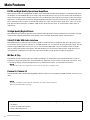
Thank you and congratulations on your purchase of the Yamaha MG12XUK
mixing console. This product is a mixing console for adjusting the balance of
multiple sound sources. This manual explains, for users who may not be familiar
with mixers, how to mix multiple sound sources during live performances by a
band or in other events. Please read this manual thoroughly to get the most out
of the product and ensure long-term, trouble-free use. After reading this man-
ual, please keep it available for future reference.
Contents
PRECAUTIONS .................................. 4
Contents ........................................ 7
Main Features ................................. 8
Quick Start Guide ............................. 9
STEP 1 Connecting external devices, such as
speakers, microphones and instruments ..... 9
STEP 2 Getting sound to the speakers .................10
Controls and Functions .....................12
Top panel
Channel section .................................................... 12
Master section ...................................................... 14
Internal effect section ........................................... 15
Rear panel
USB section .......................................................... 16
Applying Effects ..............................17
Troubleshooting ..............................18
When No Sound Is Output ................................18
Other ........................................................20
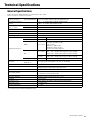
Technical Specifications ................... 21
General Specifications ................................... 21
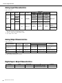
Analog Input Characteristics ............................ 22
Analog Output Characteristics .......................... 22
Digital Input / Output Characteristics .................. 22
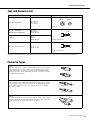
Jack and Connector List ................................. 23
Connector Types .......................................... 23
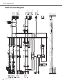
Block and Level Diagrams ............................... 24
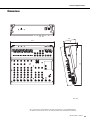
Dimensions ................................................ 25

MG12XUK Owner’s Manual
8
Main Features
D-PRE and High-Quality Operational Amplifiers
Mono input channels are equipped with “D-PRE” Class-A discrete microphone preamplifiers. The D-PRE head ampli-
fier features an inverted Darlington circuit used in high-end audio devices. This circuit uses multi-stage amplifying ele-
ments to ensure high current and low impedance, for an audio texture with crispness and richness in the low and mid
frequencies. Combined with the specially-designed “MG01” operational amp, the overall result is full-bodied reproduc-
tion of low frequencies as well as sustained high frequencies. Input channels feature combo jacks, which can accept
both XLR and TRS connectors. In addition, PAD circuitry allows line level input, to accommodate a wide variety of
instruments.
24 High-Quality Digital Effects
MG12XUK features 24 built-in effects that are based on SPX algorithms used by professionals. In particular, the high-
quality reverb and delay expand the spatial quality of the sound with remarkable realism and naturalness.
24-bit/192 kHz USB Audio Interface
MG12XUK features a USB 2.0 audio interface capable of 24-bit/192 kHz sound quality. With the audio interface you
can play back music from your computer, or use DAW software such as Cubase AI to record the mixer output. The XU
models support USB Audio Class 2.0 so you can use them with USB Audio Class 2.0 compliant tablets and other
devices, without the need to install drivers. The USB protocol uses asynchronous data transfer. Audio data is trans-
ferred based on a highly precise audio clock signal from the MG, for high quality recording and playback.
MG Rec & Play
The MG Rec & Play software application enables recording to an iPhone/iPad connected to MG12XUK, as well as
playback of songs and sounds from an iPhone/iPad.This application can be used for a wide range of purposes, such
as recording live gigs, providing background music for entertainment events, or sound effects for parties.
NOTE
iOS applications may not be supported in your area. Please check with your Yamaha dealer.
Cubase AI, Cubasis LE
The MG12XUK comes with the Steinberg DAW software "Cubase AI" and supports the DAW software "Cubasis LE" for
iPad.
NOTE
For details on MG Rec & Play, Cubase AI, and Cubasis LE, visit the Yamaha website at:
http://www.yamahaproaudio.com/mg_xu
Accessories (Please check that they are included with your mixing console.)
•AC Adaptor
• Cubase AI Download Information
• Owner’s Manual (this book)

MG12XUK Owner’s Manual
9
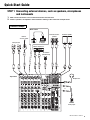
Quick Start Guide
STEP 1 Connecting external devices, such as speakers, microphones
and instruments
1. Make sure that all devices to be connected to the unit are turned off.
2. Connect speakers, microphones and instruments referring to the connection example below.
L
L
L
L
L
L
R
R
R
R
R
R
L
R
Microphones
Rear Panel
Top Panel
Electric
acoustic guitar
Computer
Electric keyboard
Footswitch
(Yamaha FC5)
Powered monitor
speaker
Powered speaker
Headphones
Portable
audio player
Connection Example

Quick Start Guide
MG12XUK Owner’s Manual
10
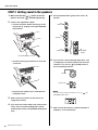
STEP 2 Getting sound to the speakers
1. Make sure that the [ / ] switch at the rear
panel is set to the [ ] position (power off).
2. Connect the supplied AC adaptor.
q Connect the power adaptor with the gap of the
plug facing up, aligning it to the [AC ADAPTOR
IN] connector.
w Turn the fastening ring clockwise to secure the
connection.
e Plug the power adaptor into a standard house-
hold power outlet.
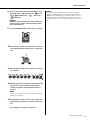
3. Make sure that all switches on the unit are not
engaged (pressed in).
4. Turn all the level control knobs fully to the left (min-
imum). These include the [GAIN] knobs (white),
[LEVEL] knobs (white), and [STEREO LEVEL] knob
(red).
5. Set the equalizer knobs (green) to the center “”
position.
6. If you connect a device with high output level, such
as a CD player or an electric keyboard, to one of the
channels 1 to 6, turn on ( ) the [PAD] switch of
the corresponding channel*.
NOTE
If you are using condenser microphones, turn on ( ) the
[PHANTOM +48V] switch.
7. Make sure that the volume of a powered speaker or
amplifier is set to the minimum.
[/] switch
[AC ADAPTOR IN] connector
AC ADAPTOR IN
4
[GAIN]
5
Equalizer
4
[LEVEL]
4
[STEREO
LEVEL]
Channel
[PAD] switch

MG12XUK Owner’s Manual
11
Quick Start Guide
8. Turn on the power to the connected devices in the
following order: (microphone), (instru-
ment), (audio device) [ / ] (this unit)
(speakers).
NOTICE
Follow this order to prevent any loud, unexpected
noise from the speakers. Reverse the order when
turning the power off.
9. Set the [STEREO LEVEL] knob to the “” position.
10. For channels to which a microphone is connected,
set the [GAIN] knob to roughly the 12 o’clock posi-
tion.
11. Set the [LEVEL] knob of each channel in use to the
“” position.
12.While playing your instrument or speaking into the
microphone, raise the volume of the powered
speaker or amplifier until the desired volume is
reached.
NOTE
If the sound is not heard or the sound is distorted, follow the
instructions on page 18.
13.Set the [LEVEL] knobs as necessary to adjust the
volume balance between the corresponding chan-
nels.
This completes the STEP 2 instructions.
NOTE
The volume can be adjusted by using three functions; [PAD],
[GAIN], and [LEVEL]. Once you set the [PAD] switch and the
[GAIN] knob, avoid adjusting those controls as much as possible.
Instead normally use the [LEVEL] knob to adjust the volume. For
details about each function, see the “Controls and Functions” sec-
tion.

MG12XUK Owner’s Manual
12
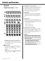
Controls and Functions
Top panel
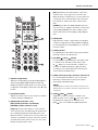
Channel section (Input: q to !4)
q [MIC/LINE] mono input jacks (channels 1-6)
For connecting a microphone, instrument, or audio
device (CD player, etc.) to the unit. These jacks support
both XLR and phone plugs.
w [PAD] switches
Turning the switch on ( ) will attenuate the sound
input to the unit. If you hear distortion or the [PEAK]
LED !0 lights, turn the switch on ( ).
NOTE
Turn the [LEVEL] knob to "0" (minimum) before toggling the
[PAD] switch on ( ) and off ( ). Otherwise, noise may
be produced.
e [HPF] (High-Pass Filter) switches
Turning the switch on ( ) will apply a high-pass filter
that attenuates frequencies below 80 Hz. When speak-
ing into the microphone, you may want to turn this
switch on ( ), in order to reduce unwanted vibration
and wind sound received by the microphone.
r [GAIN] knobs
Determines the basic volume for each of the channels 1
to 6. Adjust these so that the corresponding [PEAK]
LEDs !0 flash briefly when singing or playing the loud-
est.
t [COMP] knobs
Adjusts the amount of compression applied to the chan-
nel. As the knob is turned to the right, the threshold, the
ratio, and the output level are adjusted at the same time.
• Threshold: +22 dBu to -8 dBu
• Ratio: 1:1 to 4:1
• Output level: 0 dB to +7 dB
• Attack time: approx. 25 msec
• Release time: approx. 300 msec
y [PHANTOM +48V] switch/LED
When this switch is on ( ), the LED lights indicating
that the unit supplies DC+48 V phantom power to the
XLR plugs of the [MIC/LINE] mono input jacks q. Turn
this switch on when using a phantom-powered con-
denser microphone.
NOTICE
Be sure to leave this switch off ( ) if you do not
need phantom power. Follow the important precau-
tions below, in order to prevent noise and possible
damage to external devices as well as the unit when
you operate this switch.
• Be sure to leave this switch off when connecting
a microphone or other device that does not
require phantom power to channels 1 to 6.
• Do not connect/disconnect a cable to/from chan-
nels 1 to 6 while this switch is on.
• Turn the [LEVEL] knobs of channels 1 to 6 to the
minimum before operating this switch.

MG12XUK Owner’s Manual
13
Controls and Functions
u Equalizer (EQ) knobs
Adjust the sound quality by using the [HIGH] (high fre-
quency band), [MID] (middle frequency band), and
[LOW] (low frequency band) knobs. If you do not need
to adjust the sound quality, set the knob to the “
” (flat)
position.
i
[FX] (effect) knobs
Adjusts the volume sent from each channel to the inter-
nal effect and the [FX SEND] jack.
o [PAN] knobs (channels 1 to 6)
[BAL] knobs (channels 7/8 and 9/10)
[PAN/BAL] knobs (channels 11/12)
[PAN]: Adjusts the volume balance of each channel
sent to the stereo bus, and determines the positioning of
the sound image between left and right (stereo L/R).
When the knob is located at the 12 o’clock position, the
channel’s sound will be sent to the stereo bus channels
(L and R) at the same volume. In this case, the sound
image is positioned at the center.
[BAL]: Determines the volume balance of the stereo
channels (7/8 to 11/12) (L/R) sent to the stereo bus.
When the knob is located at the 12 o’clock position, the
sound of the stereo channels will be sent to the stereo
bus channels (L and R) at the same volume respec-
tively.
[PAN/BAL]: Provides both [PAN] and [BAL] functions.
You can use this as a [PAN] control when sound is input
to the [LINE] (L/MONO) jack, and as a [BAL] control
when sound is input to both [LINE] (L) and [LINE] (R)
jacks.
!0 [PEAK]LED
Lights when the volume of input and/or post-equalizer
sound is too high (when reaching 3 dB below clipping).
If it is lit frequently, turn the [GAIN] knob r to the left to
lower the volume.
!1 [LEVEL] knobs
For adjusting the volume balance among the channels.
Generally, set this to the “” position.
!2 [TO MON /TO ST ]switch
For selecting the output destination of the input sound
to channels 11/12. Normally set this switch to [TO
ST ]. When you use the unit with a computer con-
nected to the [USB 2.0] terminal, toggle this switch
according to your specific application, referring to the
chart in “Rear panel USB section.”
!3
[LINE] stereo input jacks (channels 7/8 to 11/12)
For connecting line-level devices such as an electric
keyboard or an audio device. These jacks support
phone plugs and RCA-pin plugs.
NOTE
Regarding input to channels 7/8 and 9/10, if both phone and
RCA-pin jacks are used at the same time, the phone jack will
take priority.
!4 [LINE /USB ] switch
Toggles the sound source input to channels 11/12.
When the switch is set to [LINE ], the source will be
the [LINE] stereo input jack !3, and when set to
[USB ], the source will be the [USB 2.0] terminal.

Controls and Functions
MG12XUK Owner’s Manual
14
Top panel
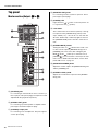
Master section (Output: !5 to @3)
!5 [FX SEND] jack
For connecting an external effects unit or a monitor sys-
tem for players. This phone-plug jack outputs the sound
adjusted with the [FX] knob respectively.
!6 [STEREO OUT] jacks
For connecting a powered speaker or amplifier. These
jacks support both XLR and phone plugs.
!7 [PHONES] output jack
For connecting a set of headphones. This jack supports
a stereo phone plug.
!8 [MONITOR OUT] jacks
For connecting a monitor system for operators. These
jacks support phone plugs.
!9 [POWER] LED
Lights when the [ / ] switch on the rear panel is set
to on (pressed to the [ ] position).
@0 Level meter
The L and R meters show the level (volume) of the sig-
nal output from the [STEREO OUT] jacks by seven
steps; “PEAK” (+17), “+10”, “+6”, “0”, “-6”, “-10”, and “-20”
dB. If the “PEAK” lamp continuously lights in red, turn
the [STEREO LEVEL] knob to the left to lower the vol-
ume.
@1 [STEREO MUTE] switch
Turning the switch on ( ) will mute the sound of ste-
reo bus from the output of [MONITOR OUT] jacks or
[PHONES] jack. In this state, when setting the [TO
MON /TO ST ] switch !2 for channels 11/12 to
[TO MON ], you can hear the sound only from chan-
nels 11/12. For details about the switch, see the “Rear
panel USB section” on page 16.
@2 [MONITOR/PHONES] knob
Adjusts the volume output to the [MONITOR OUT] jacks
and the [PHONES] jack.
@3 [STEREO LEVEL] knob
Adjusts the overall volume output from the [STEREO
OUT] jacks.

MG12XUK Owner’s Manual
15
Controls and Functions
Top panel
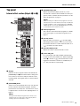
Internal effect section (Output: q to u)
q Display
Indicates the effect program number selected with the
[PROGRAM] knob w. The number flashes during selec-
tion; however, if several seconds pass without a selec-
tion being made, the program returns to the last number
selected.
w [PROGRAM] knob
Selects one of the 24 internal effects from 1-24. Turn the
knob to select the desired effect program, and then
press the knob to actually set it. For instructions on how
to apply the effect, see the section “Applying Effects” on
page 17.
NOTE
Turning the knob while pressing it down also allows you to
simultaneously select and set the effect program (without
needing to press the knob finally to set it).
e [PARAMETER] knob
Adjusts the parameter (depth, speed, etc.) for the
selected effect. The last value used with each effect pro-
gram is saved. For details about the parameter, see the
“Effect Programs” list on page 17.
NOTE
When you change to a different effect program, the unit auto-
matically restores the value that was previously used with that
program (regardless of the current position of the [PARAME-
TER] knob). Once you turn the [PARAMETER] knob, the value
of current knob position will become valid.
r Effect program list
This is the list of the internal effect programs. For details
about the programs, see the “Effect Programs” list on
page 17.
t [FX ON] switch
When the switch is turned on ( ), the switch lights
indicating the internal effect is active. If you turn off the
internal effect with the foot switch when the switch is on
( ), the LED of the switch flashes.
y [FX RTN LEVEL] knob
Adjusts the volume of the internal effect sound.
u [FOOT SW] jack
For connecting an optionally available unlatched type
footswitch, such as the Yamaha FC5. When the [FX ON]
switch t is turned on ( ), the internal effects can be
toggled on/off with the footswitch as needed with your
foot. This jack supports a phone plug.

Controls and Functions
MG12XUK Owner’s Manual
16
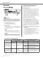
Rear panel
USB section (@4 to @6)
Caution
The unit may heat up by as much as 15 to 20°C while the
power is on. This is normal. Please note that since the panel
temperature may exceed 50°C in ambient temperatures higher
than 30°C, you should exercise caution to prevent burns.
@4 [AC ADAPTOR IN] connector
For connecting the supplied AC adaptor.
@5 [/] switch
For turning the power of the unit to standby ( ) and on
( ). The [POWER] LED !9 on the top panel lights when
the switch is set to on ( ).
NOTE
Rapidly switching the unit between on and standby in succes-
sion can cause it to malfunction. After setting the unit to
standby, wait for about six seconds before turning it on again.
NOTICE
Even when the switch is in the standby ( ) posi-
tion, electricity is still flowing to the unit. If you do
not plan to use the unit for a while, be sure to
unplug the AC adaptor from the outlet.
@6 [USB 2.0] terminal
For connecting to a computer via a commercially avail-
able USB 2.0 cable. (This product does not come with a
cable.) The sound of the stereo bus is output to the
computer. (The [STEREO LEVEL] knob @3 does not
affect the sound.) For inputs and outputs to/from the
computer, you may need a dedicated USB driver. Check
and download the driver at the following Yamaha web
site and install it to the computer before use. The cable
should be no more than 3 meters long.
http://www.yamahaproaudio.com/mg_xu/
Using the unit connected to a computer
Set the [LINE /USB ] switch !4 of channels 11/12
to [USB ]. Depending on your particular application,
you can specify the output destination and monitoring
sound by selecting the settings of the [TO MON /TO
ST ] switch !2 for channels 11/12 and the [STEREO
MUTE] switch @1. For details, see the chart below.
Adjusting the playback volume from a computer
(Attenuator)
1. Press the [PROGRAM] knob five times consecu-
tively to display the attenuation value (dB).
2. Turn the [PROGRAM] knob to set it between -24 dB
to 0 dB (minus sign is not displayed).
3. Press the [PROGRAM] knob again to exit the set-
ting. When the attenuator is enabled, the dot lights at
the lower right of the display.
Output Destinations and Monitoring Sound
*1 NOTICE: If you set the switch to [TO ST ] when you use the DAW software, a loop may be produced, possibly resulting in feed-
back.
*2 The audio signal cannot be sent to the computer because it does not pass through the stereo bus.
Application
Selection of the output destination
sent from channels 11/12
Selection of the monitoring sound with the
headphones/monitor speaker
[TO MON /TO
ST ] switch
Output destination
[STEREO MUTE]
switch
Monitoring sound
When recording with
DAW software while lis-
tening to the playback
sound from a computer.
[TO MON ]*1
[MONITOR OUT] jack*2
[PHONES] jack*2
On ( )
The direct sound (of the instrument) input to
the MG12XUK will be muted, allowing you
to hear the playback sound only from the
DAW. (Direct monitoring: Off )
Off ( )
You can hear the mixed sound of the direct
instrument sound input to the MG12XUK
and the playback sound from the
DAW.(Direct monitoring : On)
When playing back
sound from a computer.
For example: BGM play-
back, Internet broad-
casting
[TO ST ]
Stero bus
[STEREO OUT] jack
Normally set to
Off ( )
You can hear the mixed sound of the instru-
ment sound input to the MG12XUK and the
playback sound from a computer.

MG12XUK Owner’s Manual
17
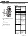
Applying Effects
The MG12XUK features high-quality built-in signal processing effects that are in the same league as our famed SPX
effect processor series. Applying effects (as described below) allows you to simulate the acoustics of different perfor-
mance environments.
1. Turn the [PROGRAM] knob to select a desired
effect program number from the effect program
list.
The currently selected effect program number flashes
on the display.
NOTE
For details about the effect programs, refer to the “Effect Pro-
grams” list on the right side.
2. Press the [PROGRAM] knob to actually select it.
The desired effect program is selected.
3. Turn on ( ) the [FX ON] switch.
4. Set the [FX RTN LEVEL] knob to the “” position.
5. Turn the [FX] knob of the channel to which you
want to apply the effect to adjust the effect amount.
Effect Programs
* “LFO” stands for Low Frequency Oscillator. An LFO is normally
used to periodically modulate another signal, using different
waveform shapes and modulation speeds.
1
3
4
1, 2
5
Effect
program list
No. Program Parameter Description
1 REV HALL 1 Reverb Time
Reverb simulating a large space
such as a concert hall.
2 REV HALL 2 Reverb Time
3 REV ROOM 1 Reverb Time
Reverb simulating the acoustics
of a small space (room).
4 REV ROOM 2 Reverb Time
5 REV STAGE 1 Reverb Time
Reverb simulating a large stage.
6 REV STAGE 2 Reverb Time
7 REV PLATE Reverb Time
Simulation of a metal-plate
reverb unit, producing a more
hard-edged reverberation.
8 DRUM AMB Reverb Time
A short reverb that is ideal for
use with a drum kit.
9 EARLY REF Room Size
An effect which isolates only the
early reflection components
from reverberation, creating a
‘flashier’ effect than conven-
tional reverb.
10 GATE REV Delay Time
An effect which cuts halfway the
tail-end of the reverberation,
making a more powerful sound.
11 SINGLE DLY Delay Time
An effect which repeats the
same sound only once. Short-
ening the delay time produces a
doubling effect.
12 DELAY Delay Time
Feedback delay adding multiple
delayed signals.
13 VOCAL ECHO Delay Time
Echo designed for conventional
vocals.
14 KARAOKE Delay Time
Echo designed for karaoke
(sing-along) applications.
15 PHASER LFO* Freq
Cyclically changes the phase to
add modulation to the sound.
16 FLANGER LFO* Freq
Adds modulation to the sound,
producing an effect similar to
the rise and fall sound of a jet
engine.
17 CHORUS 1 LFO* Freq Creates a thicker ensemble-like
sound by adding the multiple
sounds with different delay
times.
18 CHORUS 2 LFO* Freq
19 SYMPHONIC LFO* Depth
Multiplies the sound for thicker
texture.
20 TREMOLO LFO* Freq
An effect which cyclically mod-
ulates the volume.
21 AUTO WAH LFO* Freq
A wah-wah effect with cyclical
filter modulation. The [PA-RAM-
ETER] knob adjusts the speed
of the LFO* that modulates the
“wah” filter.
22 RADIO VOICE Cutoff Offset
Recreates the lo-fi sound of an
AM radio. The [PARAMETER]
knob adjusts the frequency
band to be emphasized.
23 DISTORTION Drive
Adds a sharp-edged distortion
to the sound.
24 PITCH CHANGE Pitch
An effect which changes the
pitch of the signal.

MG12XUK Owner’s Manual
18
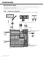
Troubleshooting
When No Sound Is Output
Refer to this section when no sound is output or the volume is very low. This information is for when sound is output from the
[STEREO OUT] jacks or the [PHONES] jack.
For details about these functions, see “Controls and Functions” on pages 12 – 16.
STEP 1 Connections and Signal Flow
Check if the instruments, microphones, and speakers are connected correctly, and if any of the cables are damaged.
DI
[PHONES] jack
[STEREO OUT] jacks
When connecting guitars
or basses to the MG, use
DI boxes.
1
Signal is input
from a micro-
phone or
instrument.
3
Route signals from channels to the master block.
2
Adjust tone and
level for each
channel.
5
The signal is output to speakers
and/or headphones.
4
Make final adjustments to the
level of the signal.

MG12XUK Owner’s Manual
19
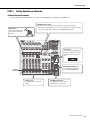
Troubleshooting
STEP 2 Setting Switches and Controls
Check the overall balance
Use the settings shown in the illustration to check the overall balance from speakers or headphones.
[GAIN] knobs
Turn until the [PEAK] indi-
cator begins to flash inter-
mittently.
Level meter
If the level meter [PEAK] indica-
tor flashes frequently, lower the
[LEVEL] knobs for each chan-
nel.
[PHANTOM +48V] switch
Turn this switch on (the indicator lit) when using a condenser microphone.
• To prevent an unwanted burst of noise from the speakers, turn off powered speak-
ers (or power amps) before turning on the [PHANTOM +48V] switch.
[PEAK]
indicators
[MONITOR/PHONES] knob
For adjusting the headphone
level and the MONITOR level.
[LEVEL] knobs
For adjusting the level for each
channel.
[STEREO LEVEL] knob
For adjusting the overall volume,
with “” as the nominal level.

Troubleshooting
MG12XUK Owner’s Manual
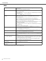
20
Other
If any specific problem should persist, please contact your Yamaha dealer.
The power does not come on. Is the mixer connected to an independent power source (generator, etc.) or a power strip
with switches?
Check that the power of that device is turned on.
No sound is output. Are external instruments (including microphones) and speakers connected correctly?
Are your cables shorted?
Are the [GAIN] knobs for each channel, [LEVEL] knobs, [STEREO LEVEL] knob adjusted to
appropriate levels?
Are the[LINE /USB ] switch set appropriately?
The sound is low, distorted, or
noisy.
Is the microphone connected to a [MIC/LINE] jack?
When using a condenser microphone, is the [PHANTOM +48V] switch turned on?
Is the [PAD] switch on?
Turn this switch off for sources with low output levels, such as microphones.
Is the output signal level for the instrument connected to the mixer appropriate?
When connecting an instrument with an output level of +4 dBu, either turn on the [PAD]
switch on a mono input channel or use a stereo input channel.
Where an input channel provides both a XLR input jack and a phone input jack, or a phone
input jack and an RCA pin jack, are there connections made at both jacks?
Use only one of these jacks.
Are the [GAIN] knobs for each channel, [LEVEL] knobs, [STEREO LEVEL] knob adjusted to
appropriate levels?
Are effect or compressor levels too high?
Use the [FX] knobs, [FX RTN LEVEL] knob, and [COMP] knobs to lower their levels.
Effects are not applied. Are the [FX] knobs for each channel adjusted to appropriate levels?
Is the [FX ON] button for [FX RTN] turned on?
Are the [PARAMETER] knob and [FX RTN LEVEL] knob adjusted to appropriate levels?
Speaking voices are not clear. Is the [HPF] switch turned on?
Is the equalizer ([HIGH]/[MID]/[LOW]) adjusted appropriately?
No mixer monitor signal is output. Are powered speakers connected to the [MONITOR OUT] jacks?
Use the [MONITOR/PHONES] knob to adjust the signal output from the [MONITOR OUT]
jacks.
Left and right levels are different
for a stereo signal input.
Is [PAN] set to the center?
If panned to the center, try reversing the left and right input connections. If, after switching
the left and right connections, the side with the low volume level also switches, check the
instrument or device that is the source of the signal.
Are you using the same type of cable to connect both the left and right input signals?
Cables with built-in resistors will attenuate the signal.
The sound level is unstable and
inconsistent.
Is the compressor level set too high?
Use the [COMP] knob to lower the level.
The volume of audio play-back
from a computer need to be
adjusted.
Use the “Attenuator Function”. For details, see page 16.
La page charge ...
La page charge ...
La page charge ...
La page charge ...
La page charge ...
La page charge ...
La page charge ...
La page charge ...
-
 1
1
-
 2
2
-
 3
3
-
 4
4
-
 5
5
-
 6
6
-
 7
7
-
 8
8
-
 9
9
-
 10
10
-
 11
11
-
 12
12
-
 13
13
-
 14
14
-
 15
15
-
 16
16
-
 17
17
-
 18
18
-
 19
19
-
 20
20
-
 21
21
-
 22
22
-
 23
23
-
 24
24
-
 25
25
-
 26
26
-
 27
27
-
 28
28


Yamaha MG12XUK Le manuel du propriétaire
- Catégorie
- Amplificateurs audio
- Taper
- Le manuel du propriétaire
dans d''autres langues
- italiano: Yamaha MG12XUK Manuale del proprietario
- English: Yamaha MG12XUK Owner's manual
- español: Yamaha MG12XUK El manual del propietario
- Deutsch: Yamaha MG12XUK Bedienungsanleitung
- русский: Yamaha MG12XUK Инструкция по применению
- Nederlands: Yamaha MG12XUK de handleiding
- português: Yamaha MG12XUK Manual do proprietário
- dansk: Yamaha MG12XUK Brugervejledning
- polski: Yamaha MG12XUK Instrukcja obsługi
- čeština: Yamaha MG12XUK Návod k obsluze
- svenska: Yamaha MG12XUK Bruksanvisning
- 日本語: Yamaha MG12XUK 取扱説明書
- Türkçe: Yamaha MG12XUK El kitabı
- suomi: Yamaha MG12XUK Omistajan opas
- română: Yamaha MG12XUK Manualul proprietarului
Documents connexes
-
Yamaha MG10XUF Manuel utilisateur
-
Yamaha MG06X Le manuel du propriétaire
-
Yamaha MG16 spécification
-
Yamaha MG20XU spécification
-
-
-
Yamaha n12 Le manuel du propriétaire
-
Yamaha MG10 Manuel utilisateur
-
-
Yamaha MW10c Le manuel du propriétaire
