Sony VPL-VW70 Mode d'emploi
- Catégorie
- Projecteurs de données
- Taper
- Mode d'emploi

VPL-VW70
© 2008 Sony Corporation
4-125-589-11 (1)
Video Projector
Operating Instructions
Mode d’emploi
GB
FR

GB
2
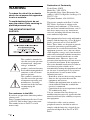
WARNING
To reduce the risk of fire or electric
shock, do not expose this apparatus
to rain or moisture.
To avoid electrical shock, do not
open the cabinet. Refer servicing to
qualified personnel only.
THIS APPARATUS MUST BE
EARTHED.
For customers in the USA
If you have any questions about this product,
you may call:
Sony Customer Information Service Center
1-800-222-7669 or http://www.sony.com/
The number below is for FCC related
matters only.
Declaration of Conformity
Trade Name: SONY
Model No.: VPL-VW70
Responsible Party: Sony Electronics Inc.
Address: 16530 Via Esprillo, San Diego, CA
92127 U.S.A.
Telephone Number: 858-942-2230
This device complies with Part 15 of the
FCC Rules. Operation is subject to the
following two conditions: (1) This device
may not cause harmful interference, and (2)
this device must accept any interference
received, including interference that may
cause undesired operation.
This equipment has been tested and found to
comply with the limits for a Class B digital
device, pursuant to Part 15 of the FCC
Rules. These limits are designed to provide
reasonable protection against harmful
interference in a residential installation. This
equipment generates, uses, and can radiate
radio frequency energy and, if not installed
and used in accordance with the instructions,
may cause harmful interference to radio
communications. However, there is no
guarantee that interference will not occur in
a particular installation. If this equipment
does cause harmful interference to radio or
television reception, which can be
determined by turning the equipment off and
on, the user is encouraged to try to correct
the interference by one or more of the
following measures:
- Reorient or relocate the receiving antenna.
- Increase the separation between the
equipment and receiver.
- Connect the equipment into an outlet on a
circuit different from that to which the
receiver is connected.
- Consult the dealer or an experienced radio/
TV technician for help.
You are cautioned that any changes or
modifications not expressly approved in this
manual could void your authority to operate
this equipment.
All interface cables used to connect
peripherals must be shielded in order to
comply with the limits for a digital device
pursuant to Subpart B of Part 15 of FCC
Rules.
This symbol is intended to
alert the user to the presence
of uninsulated “dangerous
voltage” within the
product’s enclosure that may
be of sufficient magnitude to
constitute a risk of electric
shock to persons.
This symbol is intended to
alert the user to the presence
of important operating and
maintenance (servicing)
instructions in the literature
accompanying the
appliance.

3
GB
Disposal of Used Lamp
This projector’s lamp contains mercury and
should be disposed of properly. Consult your
local authorities regarding safe disposal.
The material contained in this lamp are
similar to those of a fluorescent lamp, so you
should dispose of it in the same way.
For customers in the United States
Lamp in this product contains mercury.
Disposal of these materials may be regulated
due to environmental considerations. For
disposal or recycling information, please
contact your local authorities or the
Electronic Industries Alliance
(www.eiae.org).
For customers in Canada
This Class B digital apparatus complies with
Canadian ICES-003.
Installing batteries
Two R6 (size AA) batteries are supplied for
Remote Commander.
To avoid risk of explosion, use R6 (size AA)
manganese or alkaline batteries.
Trademark Information
HDMI, the HDMI logo and High-Definition
Multimedia Interface are trademarks or
registered trademarks of HDMI Licensing
LLC.
“Blu-ray Disc” is a trademark.
The socket-outlet should be installed near
the equipment and be easily accessible.
CAUTION
RISK OF EXPLOSION IF BATTERY IS
REPLACED BY AN INCORRECT
TYPE.
DISPOSED OF USED BATTERIES
ACCORDING TO THE LOCAL RULES.
GB

GB
4
Table of Contents
Precautions ......................................... 6
Front/Right Side ................................. 7
Rear/Bottom ....................................... 8
Remote Control .................................. 9
Unpacking ........................................10
Step 1: Installing the
Projector ........................................... 11
Before Setting Up the
Projector ..................................... 11
Positioning the Projector and a
Screen ......................................... 13
Step 2: Connecting the Projector ..... 17
Connecting to a VCR ................. 17
Connecting to a Computer ......... 20
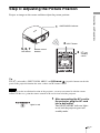
Step 3: Adjusting the Picture
Position ............................................ 21
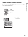
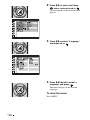
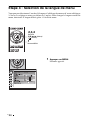
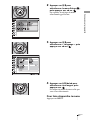
Step 4: Selecting the Menu
Language .......................................... 27
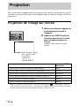
Projecting the Picture on the
Screen ...............................................29
Turning Off the Power ................30
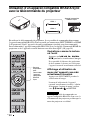
Operating the BRAVIA Sync
Compatible Equipment with the
Remote Control of the Projector ......31
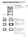
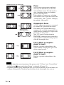
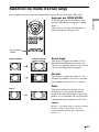
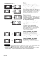
Selecting the Wide Screen Mode .....33
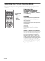
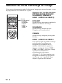
Selecting the Picture Viewing
Mode ................................................36
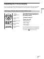
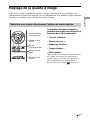
Adjusting the Picture Quality ...........37
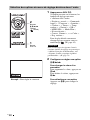
Selecting to Directly Adjust the
Desired Menu Item .....................37
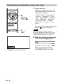
Selecting Desired Adjust Menu
Items in the Order .......................38
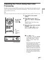
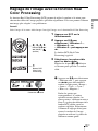
Adjusting the Picture Using Real
Color Processing ...............................39
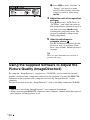
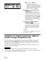
Using the Supplied Software to
Adjust the Picture Quality
(ImageDirector3) ..............................40
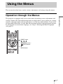
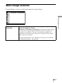
Operation through the Menus ...........41
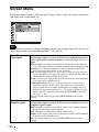
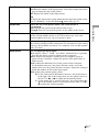
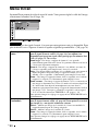
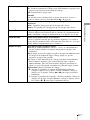
Picture Menu ....................................45
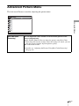
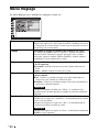
Advanced Picture Menu ...................49
Screen Menu .....................................50
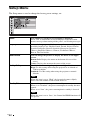
Setup Menu .......................................52
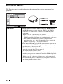
Function Menu .................................54
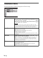
Installation Menu ..............................56
Information Menu .............................59
About the Preset Memory No. ....59
Location of Controls
Connections and
Preparations
Projecting
Using the Menus

5
GB
About the Control for HDMI ...........60
About the x.v.Color ..........................61
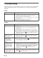
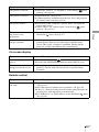
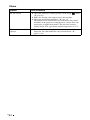
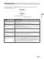
Troubleshooting ...............................62
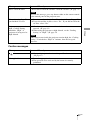
Warning Indicators .....................65
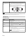
Message Lists .............................66
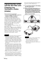
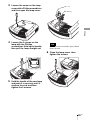
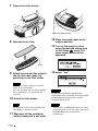
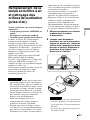
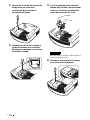
Replacing the Lamp and the Air Filter
and Cleaning the Ventilation Holes
(intake) .............................................68
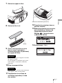
Cleaning the Air Filter .....................71
Cleaning and the Screen of the
Projector ...........................................71
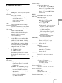
Specifications ...................................73
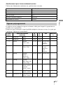
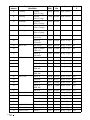
Preset Signals .............................75
Input Signals and Adjustable/
Setting Items ...............................78
Ceiling Installation ...........................80
Index ...............................................84
Others

GB
6
Precautions
On safety
• Check that the operating voltage of your
unit is identical with the voltage of your
local power supply.
• Should any liquid or solid object fall into
the cabinet, unplug the unit and have it
checked by qualified personnel before
operating it further.
• Unplug the unit from the wall outlet if it is
not to be used for several days.
• To disconnect the cord, pull it out by the
plug. Never pull the cord itself.
• The wall outlet should be near the unit and
easily accessible.
• The unit is not disconnected to the AC
power source (mains) as long as it is
connected to the wall outlet, even if the
unit itself has been turned off.
• Do not look into the lens while the lamp is
on.
• Do not place your hand or objects near the
ventilation holes. The air coming out is
hot.
On preventing internal heat build-
up
After you turn off the power with the ?/1
(on/standby) switch, do not disconnect the
unit from the wall outlet while the cooling
fan is still running.
Caution
The projector is equipped with ventilation
holes (intake) and ventilation holes
(exhaust). Do not block or place anything
near these holes, or internal heat build-up
may occur, causing picture degradation or
damage to the projector.
On repacking
Save the original shipping carton and
packing material; they will come in handy if
you ever have to ship your unit. For
maximum protection, repack your unit as it
was originally packed at the factory.

7
GB
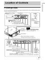
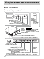
Location of Controls
Front/Right Side
You can use the buttons on the control panel with the same names as those on the remote
control to operate the projector.
Location of Controls
INPUT button (1 page 29)
MENU button (1 page 41)
ON/STANDBY
indicator
(1 page 21)
Remote control detector (1 page 21)
Ventilation
holes (exhaust)
(1 page 12)
?/1 (on/standby) switch (1 page 22)
LAMP/COVER
indicator
(1 page 65)
M/m/</, (arrow)/
(enter) button (1 page 41)
Ventilation holes (exhaust) (1 page 12)
- AC IN socket
S VIDEO INPUT connector (mini DIN 4-pin)/VIDEO INPUT
connector (phono type) (1 page 19)
Y PB/CB PR/CR connector (phono type) (1 page 17)
INPUT A connector (1 page 20)
HDMI 1 connector (1 page 18)
REMOTE
connector
Connects to a
computer, etc.
for remote
control.
(1 page 40)
HDMI 2 connector (1 page 18)
While the ON/STANDBY indicator
lights in orange, the power saving
mode is on. (1 page 53)
Note
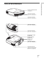
Control panel
LENS button
Open button
TRIGGER 1 connector
Outputs 12V signal when the projector is on.
TRIGGER 2 connector
Outputs 12V signal when “Wide Mode” is set to “Anamorphic Zoom”. (1 page 34)
Press the button and open
the cover.
Lens protector

GB
8
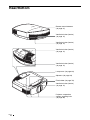
Rear/Bottom
Filter holder (1 page 70)
Ventilation holes (intake)
(1 page 12)
Lamp cover (1 page 69)
Ventilation holes (intake)
(1 page 12)
Projector suspension
support attaching hole
(1 page 80)
Adjusters (1 page 26)
Ventilation holes (intake)
(1 page 12)
Ventilation holes (intake)
(1 page 12)
Ventilation holes (intake)
(1 page 12)
Remote control detector
(1 page 21)

9
GB
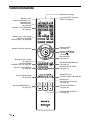
Location of Controls
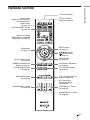
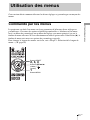
Remote Control
Infrared transmitter
?/1 (on/standby)
switch (1 page 22)
COLOR SPACE button
(1 page 37)
M/m/</, (arrow)/
(enter) buttons
(1 page 41)
RESET button
(1 page 41)
CONTRAST +/– button
(1 page 46)
BRIGHTNESS +/– button
(1 page 46)
INPUT button
(1 page 29)
LIGHT button
Illuminates the buttons on
the remote control.
PICTURE MODE buttons
(1 page 36)
ADJ PIC (Adjust Picture)
button (1 page 38)
WIDE MODE button
(1 page 33)
Buttons to operate
BRAVIA Sync compatible
equipment (1 page 31)
LENS button
(1 page 21)
SHARPNESS +/– button
(1 page 46)
MENU button
(1 page 41)
ADVANCED IRIS button
(1 page 37)
COLOR TEMP button
(1 page 37)
RCP (Real Color
Processing) button
(1 page 39)
BLACK LEVEL button
(1 page 37)
GAMMA CORRECTION
button (1 page 37)

GB
10
This section describes how to install the projector and screen, how to connect the
equipment from which you want to project the picture, etc.
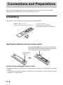
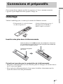
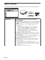
Unpacking
Check the carton to make sure it contains the following items:
Inserting the batteries into the remote control
Caution about handling the remote control
• Handle the remote control with care. Do not drop or step on it, or spill liquid of any kind
onto it.
• Do not place the remote control in a location near a heat source, a place subject to direct
sunlight, or a damp room.
Connections and Preparations
• Remote control (1) and
Size AA (R6) manganese batteries (2)
• AC power cord (1)
• ImageDirector3 CD-ROM (1)
• Operating Instructions (this manual)
Insert the batteries E side first as shown in the illustration.
Inserting them forcibly or with the polarities reversed may
cause a short circuit and may generate heat.
Push and slide
to open.

11
GB
Connections and Preparations
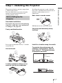
Step 1: Installing the Projector
The projector displays pictures output from
a VCR or other device.
The lens shift allows you to have broader
options for placing the projector and
viewing pictures easily.
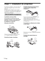
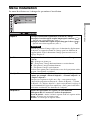
Unsuitable installation
Do not place the projector in the following
situations, which may cause malfunction
or damage to the projector.
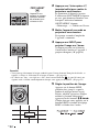
Poorly ventilated location
Leave space of more than 30 cm (11
7
/
8
inches)
around the unit.
Hot and humid
Locations subject to direct cool or
warm air from an air-conditioner
Installing the projector in such a location
may cause a malfunction of the unit due to
moisture condensation or rise in
temperature.
Near a heat or smoke sensor
Malfunction of the sensor may occur.
Very dusty and extremely smoky
locations
Install in a location away from walls
To maintain the performance and
reliability of the projector, allow at
least 30 cm (11 7/8 inches) between
the projector and walls.
Before Setting Up the
Projector
30 cm
(11
7
/
8
inches)
30 cm
(11
7
/
8
inches)
30 cm
(11
7
/
8
inches)
30 cm
(11
7
/
8
inches)

GB
12
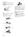
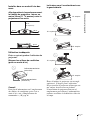
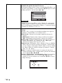
Improper use
Do not do any of the following while using
the projector.
Blocking the ventilation holes (intake
or exhaust)
Tip
For details on the location of the ventilation
holes (intake or exhaust), see “Location of
Controls” on page 7.
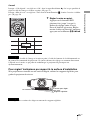
Tilting front/rear and left/right
Avoid using the projector tilted at an angle
of more than 15 degrees.
Do not install the projector anywhere other
than on a level surface or on the ceiling.
Installing the projector in such a location
may result in uneven color uniformity or
reduce the reliability of the effects of the
lamp.
When installing the unit at high
altitudes
When using the projector at an altitude of
1,500 m or higher, set “Cooling Setting” in the
Setup menu to “High” (1 page 52).
Failing to set this mode when using the
projector at high altitudes could have adverse
effects, such as reducing the reliability of
certain components.
Ventilation holes
(exhaust)
Ventilation holes
(intake)
15° or more
15° or more
15° or more
15° or more
15° or more

13
GB
Connections and Preparations
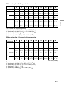
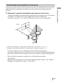
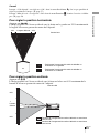
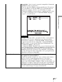
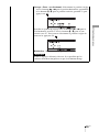
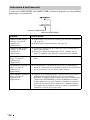
The installation distance between the projector and a screen varies depending on the size
of the screen or whether or not you use the lens shift features.
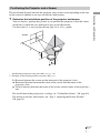
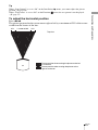
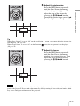
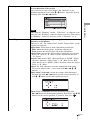
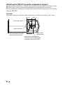
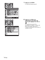
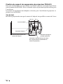
1 Determine the installation position of the projector and screen.
You can obtain a good quality picture if you position the projector so that the center
of the lens is within the area indicated in gray in the illustration.
Use the values L, x and y in the table on page 14 or 15 as a guide.
* Installation position not using lens shift (x = 0, y = 0)
** Example of installation position using lens shift (x, y)
L: Distance between the screen and the front end of the projector’s lens.
x: Horizontal distance between the center of the screen and the center of the
projector’s lens.
y: Vertical distance between the center of the screen and the center of the projector’s
lens.
For installation of the projector on a ceiling, see “Ceiling Installation.” (1 page 80)
For details on the lens shift feature, see “Step 3: Adjusting the Picture Position.”
(1 page 21)
Positioning the Projector and a Screen
Screen
*
**

GB
14
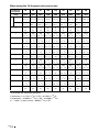
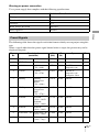
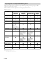
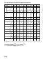
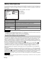
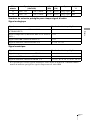
When using the 16:9 aspect ratio screen size
Unit: mm (inches)
To calculate the installation positions
L (minimum) = 31.1781 (1
7
/
32
) × SS – 46.1543 (1
13
/
16
)
L (maximum) = 47.0644 (1
27
/
32
) × SS – 42.3308 (1
21
/
32
)
y = –1.463 × x (mm or inch) + 8.0942 (
5
/
16
) × SS
Screen Size
SS (inches)
40 60 80 100 120 150 200 250 300
(mm) 1016 1524 2032 2540 3048 3810 5080 6350 7620
L
minimum 1201 1825 2448 3072 3695 4631 6189 7748 9307
(47
3
/
8
) (71
7
/
8
) (96
1
/
2
) (121) (145
1
/
2
) (182
3
/
8
) (243
3
/
4
) (305
1
/
8
) (366
1
/
2
)
maximum 1840 2782 3723 4664 5605 7017 9371 11724 14077
(72
1
/
2
) (109
5
/
8
) (146
5
/
8
) (183
5
/
8
) (220
3
/
4
) (276
3
/
8
) (369) (461
5
/
8
) (554
1
/
4
)
x 000000000
(0) (0) (0) (0) (0) (0) (0) (0) (0)
y 324 486 648 809 971 1214 1619 2024 2428
(12
7
/
8
)(19
1
/
4
)(25
5
/
8
)(31
7
/
8
)(38
1
/
4
)(47
7
/
8
)(63
3
/
4
)(79
3
/
4
)(95
5
/
8
)
x 44 66 89 111 133 166 221 277 332
(1
3
/
4
)(2
5
/
8
)(3
5
/
8
)(4
3
/
8
)(5
1
/
4
)(6
5
/
8
)(8
3
/
4
) (11) (13
1
/
8
)
y 259 389 518 648 777 971 1295 1619 1943
(10
1
/
4
)(15
3
/
8
)(20
1
/
2
)(25
5
/
8
)(30
5
/
8
)(38
1
/
4
)(51)(63
3
/
4
)(76
1
/
2
)
x 89 133 177 221 266 332 443 553 664
(3
5
/
8
)(5
1
/
4
)(7)(8
3
/
4
)(10
1
/
2
)(13
1
/
8
)(17
1
/
2
)(21
7
/
8
)(26
1
/
4
)
y 194 291 389 486 583 728 971 1214 1457
(7
3
/
4
)(11
1
/
2
)(15
3
/
8
)(19
1
/
4
)(23)(28
3
/
4
)(38
1
/
4
)(47
7
/
8
)(57
3
/
8
)
x 133 199 266 332 398 498 664 830 996
(5
1
/
4
)(7
7
/
8
)(10
1
/
2
)(13
1
/
8
)(15
3
/
4
)(19
5
/
8
)(26
1
/
4
)(32
3
/
4
)(39
1
/
4
)
y 130 194 259 324 389 486 648 809 971
(5
1
/
8
)(7
3
/
4
)(10
1
/
4
)(12
7
/
8
)(15
3
/
8
)(19
1
/
4
)(25
5
/
8
)(31
7
/
8
)(38
1
/
4
)
x 177 266 354 443 531 664 886 1107 1328
(7) (10
1
/
2
)(14)(17
1
/
2
)(21)(26
1
/
4
)(35)(43
5
/
8
)(52
3
/
8
)
y 65 97 130 162 194 243 324 405 486
(2
5
/
8
)(3
7
/
8
)(5
1
/
8
)(6
1
/
2
)(7
3
/
4
)(9
5
/
8
)(12
7
/
8
)(16)(19
1
/
4
)
x 221 332 443 553 664 830 1107 1384 1660
(8
3
/
4
)(13
1
/
8
)(17
1
/
2
)(21
7
/
8
)(26
1
/
4
)(32
3
/
4
)(43
5
/
8
)(54
1
/
2
)(65
3
/
8
)
y 000000000
(0) (0) (0) (0) (0) (0) (0) (0) (0)

15
GB
Connections and Preparations
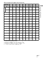
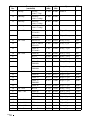
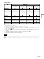
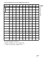
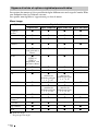
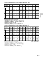
When using the 4:3 aspect ratio screen size
Unit: mm (inches)
To calculate the installation positions
L (minimum) = 38.1569 (1
1
/
2
) × SS – 46.1543 (1
13
/
16
)
L (maximum) = 57.5992 (2
9
/
32
) × SS – 42.3308 (1
21
/
32
)
y = –1.463 × x (mm or inch) + 9.9060 (
3
/
8
) × SS
Screen Size
SS (inches)
40 60 80 100 120 150 200 250 300
(mm) 1016 1524 2032 2540 3048 3810 5080 6350 7620
L
minimum 1480 2243 3006 3770 4533 5677 7585 9493 11401
(58
3
/
8
)(88
3
/
8
) (118
3
/
8
) (148
1
/
2
) (178
1
/
2
) (223
5
/
8
) (298
5
/
8
) (373
3
/
4
) (448
7
/
8
)
maximum 2262 3414 4566 5718 6870 8598 11478 14357 17237
(89
1
/
8
) (134
1
/
2
) (179
7
/
8
) (225
1
/
8
) (270
1
/
2
) (338
5
/
8
) (452) (565
1
/
4
) (678
5
/
8
)
x 000000000
(0) (0) (0) (0) (0) (0) (0) (0) (0)
y 396 594 792 991 1189 1486 1981 2477 2972
(15
5
/
8
)(23
1
/
2
) (31
1
/
4
)(39
1
/
8
)(46
7
/
8
)(58
5
/
8
)(78)(97
5
/
8
)
(117
1
/
8
)
x 54 81 108 135 163 203 271 339 406
(2
1
/
4
)(3
1
/
4
)(4
3
/
8
)(5
3
/
8
)(6
1
/
2
)(8)(10
3
/
4
)(13
3
/
8
)(16)
y 317 475 634 792 951 1189 1585 1981 2377
(12
1
/
2
)(18
3
/
4
)(25)(31
1
/
4
)(37
1
/
2
)(46
7
/
8
)(62
1
/
2
)(78)(93
5
/
8
)
x 108 163 217 271 325 406 542 677 813
(4
3
/
8
)(6
1
/
2
)(8
5
/
8
)(10
3
/
4
)(12
7
/
8
)(16)(21
3
/
8
)(26
3
/
4
)(32
1
/
8
)
y 238 357 475 594 713 892 1189 1486 1783
(9
3
/
8
)(14
1
/
8
) (18
3
/
4
)(23
1
/
2
)(28
1
/
8
)(35
1
/
8
)(46
7
/
8
)(58
5
/
8
)(70
1
/
4
)
x 163 244 325 406 488 610 813 1016 1219
(6
1
/
2
)(9
5
/
8
) (12
7
/
8
)(16)(19
1
/
4
)(24
1
/
8
)(32
1
/
8
)(40) (48)
y 158 238 317 396 475 594 792 991 1189
(6
1
/
4
)(9
3
/
8
) (12
1
/
2
)(15
5
/
8
)(18
3
/
4
)(23
1
/
2
)(31
1
/
4
)(39
1
/
8
)(46
7
/
8
)
x 217 325 433 542 650 813 1084 1355 1626
(8
5
/
8
)(12
7
/
8
) (17
1
/
8
)(21
3
/
8
)(25
5
/
8
)(32
1
/
8
)(42
3
/
4
)(53
3
/
8
)(64
1
/
8
)
y 79 119 158 198 238 297 396 495 594
(3
1
/
8
)(4
3
/
4
)(6
1
/
4
)(7
7
/
8
)(9
3
/
8
)(11
3
/
4
)(15
5
/
8
)(19
1
/
2
)(23
1
/
2
)
x 271 406 542 677 813 1016 1355 1693 2032
(10
3
/
4
) (16) (21
3
/
8
)(26
3
/
4
)(32
1
/
8
)(40)(53
3
/
8
)(66
3
/
4
)(80)
y 000000000
(0) (0) (0) (0) (0) (0) (0) (0) (0)

GB
16
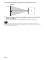
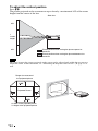
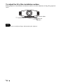
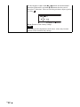
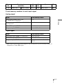
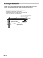
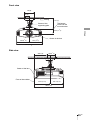
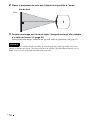
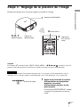
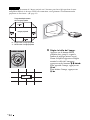
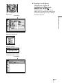
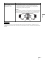
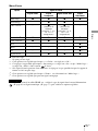
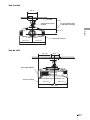
2 Position the projector so that the lens is parallel to the screen.
3 Project an image on the screen and adjust the picture so that it fits the
screen. (1 page 21)
To project an image, connect video equipment to the projector. (1 page 17)
When using a screen with an uneven surface, stripes pattern may rarely appear on the screen
depending on the distance between the screen and the projector or the zooming magnifications. This
is not a malfunction of the projector.
Note
Screen
Top view

17
GB
Connections and Preparations
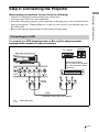
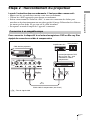
Step 2: Connecting the Projector
When making connections, be sure to do the following:
• Turn off all equipment before making any connections.
• Use the proper cables for each connection.
• Insert the cable plugs properly; poor connection at the plugs may cause a malfunction or
poor picture quality. When pulling out a cable, be sure to pull it out from the plug, not
the cable itself.
• Refer to the operating instructions of the connected equipment.
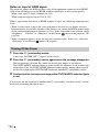
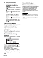
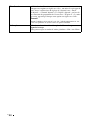
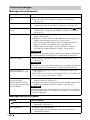
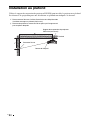
To connect to a DVD player/recorder or Blu-ray Disc player/recorder
equipped with component video connectors
Connecting to a VCR
Component video cable (not supplied)
: Video signal flow
DVD player/recorder,
Blu-ray Disc player/recorder,
etc., with component video
connectors
Right side of the projector
AV amplifier
Speakers

GB
18
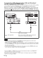
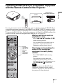
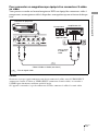
To connect to a DVD player/recorder or Blu-ray Disc player/
recorder equipped with HDMI output
You can enjoy better picture quality by connecting a DVD player/recorder or Blu-ray Disc
player/recorder equipped with HDMI output to the HDMI input of the projector.
Moreover, if you have a Control for HDMI compatible equipment, you can operate the
projector synchronizing with the Control for HDMI compatible equipment. For details,
see the Function menu (1 page 54) and “About the Control for HDMI” (1 page 60).
• When connecting equipment to the HDMI input of the projector, be sure to use
equipment that have acquired the HDMI logo.
• When connecting an HDMI cable to the projector, make sure the
V mark on the upper
part of the HDMI input of the projector and the
v mark on the connector of the cable is
set at the same position.
• If the picture from equipment connected to the projector with an HDMI cable is not
clear, check the settings of the connected equipment.
Notes
HDMI cable (not supplied)
: Video signal flow
Right side of the projector
DVD player/recorder or Blu-
ray Disc player/recorder,
etc., with the HDMI output
to HDMI output
AV amplifier
Speakers
When using an optional HDMI cable, be sure to use
a cable that has acquired the HDMI logo.
............................................................................................................................................................
Control for HDMI is an HDMI standard mutual control function which uses the HDMI CEC
(Consumer Electronics Control) specification.
This projector supports DeepColor, x.v.Color, LipSync and computer input signal of HDMI
standards. It also supports HDCP.

19
GB
Connections and Preparations
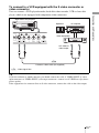
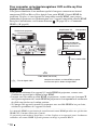
To connect to a VCR equipped with the S video connector or
video connector
You can connect a DVD player/recorder, hard disk video recorder, VCR or laser disk
player, which is not equipped with component video connectors.
Tip
If you do not know to which connector you should connect the cable, S VIDEO INPUT (S video
input connector) or VIDEO INPUT (video input connector), connect it to S VIDEO to enjoy better
picture quality.
If the equipment to be connected has no S video connector, connect the cable to the video output.
S video or video cable (not supplied)
: Video signal flow
Right side of the projector
to S video or
video output
Video equipment
AV amplifier
Speakers

GB
20
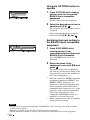
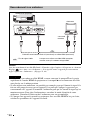
Tip
When connecting an HD-Dsub15 pin cable, set “Input-A Signal Sel.” in the Setup menu to
“Auto” or “Computer.” If the input signal does not appear properly, set it to “Computer.” (1
pages 53, 66)
• When connecting an HDMI cable, make sure the V mark on the upper part of the HDMI
input of the projector and the
v mark on the connector of the cable is set at the same
position.
• If you set your computer, such as a notebook type, to output the signal to both
computer’s display and this equipment, the picture of the equipment may not appear
properly. Set your computer to output the signal to only the external monitor.
For details, refer to the computer’s operating instructions supplied with your computer.
For settings of the computer, consult with the manufacturer of the computer.
• If the picture from equipment connected to the projector with an HDMI cable is not
clear, check the settings of the connected equipment.
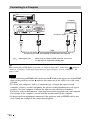
Connecting to a Computer
Notes
HD-Dsub15 pin cable (not supplied) or HDMI cable (not supplied)
: Video signal flow
Right side of the projector
to monitor output
Computer
When using an optional HDMI cable, be sure to use
a cable that has acquired the HDMI logo.
La page est en cours de chargement...
La page est en cours de chargement...
La page est en cours de chargement...
La page est en cours de chargement...
La page est en cours de chargement...
La page est en cours de chargement...
La page est en cours de chargement...
La page est en cours de chargement...
La page est en cours de chargement...
La page est en cours de chargement...
La page est en cours de chargement...
La page est en cours de chargement...
La page est en cours de chargement...
La page est en cours de chargement...
La page est en cours de chargement...
La page est en cours de chargement...
La page est en cours de chargement...
La page est en cours de chargement...
La page est en cours de chargement...
La page est en cours de chargement...
La page est en cours de chargement...
La page est en cours de chargement...
La page est en cours de chargement...
La page est en cours de chargement...
La page est en cours de chargement...
La page est en cours de chargement...
La page est en cours de chargement...
La page est en cours de chargement...
La page est en cours de chargement...
La page est en cours de chargement...
La page est en cours de chargement...
La page est en cours de chargement...
La page est en cours de chargement...
La page est en cours de chargement...
La page est en cours de chargement...
La page est en cours de chargement...
La page est en cours de chargement...
La page est en cours de chargement...
La page est en cours de chargement...
La page est en cours de chargement...
La page est en cours de chargement...
La page est en cours de chargement...
La page est en cours de chargement...
La page est en cours de chargement...
La page est en cours de chargement...
La page est en cours de chargement...
La page est en cours de chargement...
La page est en cours de chargement...
La page est en cours de chargement...
La page est en cours de chargement...
La page est en cours de chargement...
La page est en cours de chargement...
La page est en cours de chargement...
La page est en cours de chargement...
La page est en cours de chargement...
La page est en cours de chargement...
La page est en cours de chargement...
La page est en cours de chargement...
La page est en cours de chargement...
La page est en cours de chargement...
La page est en cours de chargement...
La page est en cours de chargement...
La page est en cours de chargement...
La page est en cours de chargement...
La page est en cours de chargement...
La page est en cours de chargement...
La page est en cours de chargement...
La page est en cours de chargement...
La page est en cours de chargement...
La page est en cours de chargement...
La page est en cours de chargement...
La page est en cours de chargement...
La page est en cours de chargement...
La page est en cours de chargement...
La page est en cours de chargement...
La page est en cours de chargement...
La page est en cours de chargement...
La page est en cours de chargement...
La page est en cours de chargement...
La page est en cours de chargement...
La page est en cours de chargement...
La page est en cours de chargement...
La page est en cours de chargement...
La page est en cours de chargement...
La page est en cours de chargement...
La page est en cours de chargement...
La page est en cours de chargement...
La page est en cours de chargement...
La page est en cours de chargement...
La page est en cours de chargement...
La page est en cours de chargement...
La page est en cours de chargement...
La page est en cours de chargement...
La page est en cours de chargement...
La page est en cours de chargement...
La page est en cours de chargement...
La page est en cours de chargement...
La page est en cours de chargement...
La page est en cours de chargement...
La page est en cours de chargement...
La page est en cours de chargement...
La page est en cours de chargement...
La page est en cours de chargement...
La page est en cours de chargement...
La page est en cours de chargement...
La page est en cours de chargement...
La page est en cours de chargement...
La page est en cours de chargement...
La page est en cours de chargement...
La page est en cours de chargement...
La page est en cours de chargement...
La page est en cours de chargement...
La page est en cours de chargement...
La page est en cours de chargement...
La page est en cours de chargement...
La page est en cours de chargement...
La page est en cours de chargement...
La page est en cours de chargement...
La page est en cours de chargement...
La page est en cours de chargement...
La page est en cours de chargement...
La page est en cours de chargement...
La page est en cours de chargement...
La page est en cours de chargement...
La page est en cours de chargement...
La page est en cours de chargement...
La page est en cours de chargement...
La page est en cours de chargement...
La page est en cours de chargement...
La page est en cours de chargement...
La page est en cours de chargement...
La page est en cours de chargement...
La page est en cours de chargement...
La page est en cours de chargement...
La page est en cours de chargement...
La page est en cours de chargement...
La page est en cours de chargement...
La page est en cours de chargement...
La page est en cours de chargement...
La page est en cours de chargement...
La page est en cours de chargement...
La page est en cours de chargement...
La page est en cours de chargement...
La page est en cours de chargement...
La page est en cours de chargement...
La page est en cours de chargement...
La page est en cours de chargement...
La page est en cours de chargement...
La page est en cours de chargement...
La page est en cours de chargement...
La page est en cours de chargement...
La page est en cours de chargement...
-
 1
1
-
 2
2
-
 3
3
-
 4
4
-
 5
5
-
 6
6
-
 7
7
-
 8
8
-
 9
9
-
 10
10
-
 11
11
-
 12
12
-
 13
13
-
 14
14
-
 15
15
-
 16
16
-
 17
17
-
 18
18
-
 19
19
-
 20
20
-
 21
21
-
 22
22
-
 23
23
-
 24
24
-
 25
25
-
 26
26
-
 27
27
-
 28
28
-
 29
29
-
 30
30
-
 31
31
-
 32
32
-
 33
33
-
 34
34
-
 35
35
-
 36
36
-
 37
37
-
 38
38
-
 39
39
-
 40
40
-
 41
41
-
 42
42
-
 43
43
-
 44
44
-
 45
45
-
 46
46
-
 47
47
-
 48
48
-
 49
49
-
 50
50
-
 51
51
-
 52
52
-
 53
53
-
 54
54
-
 55
55
-
 56
56
-
 57
57
-
 58
58
-
 59
59
-
 60
60
-
 61
61
-
 62
62
-
 63
63
-
 64
64
-
 65
65
-
 66
66
-
 67
67
-
 68
68
-
 69
69
-
 70
70
-
 71
71
-
 72
72
-
 73
73
-
 74
74
-
 75
75
-
 76
76
-
 77
77
-
 78
78
-
 79
79
-
 80
80
-
 81
81
-
 82
82
-
 83
83
-
 84
84
-
 85
85
-
 86
86
-
 87
87
-
 88
88
-
 89
89
-
 90
90
-
 91
91
-
 92
92
-
 93
93
-
 94
94
-
 95
95
-
 96
96
-
 97
97
-
 98
98
-
 99
99
-
 100
100
-
 101
101
-
 102
102
-
 103
103
-
 104
104
-
 105
105
-
 106
106
-
 107
107
-
 108
108
-
 109
109
-
 110
110
-
 111
111
-
 112
112
-
 113
113
-
 114
114
-
 115
115
-
 116
116
-
 117
117
-
 118
118
-
 119
119
-
 120
120
-
 121
121
-
 122
122
-
 123
123
-
 124
124
-
 125
125
-
 126
126
-
 127
127
-
 128
128
-
 129
129
-
 130
130
-
 131
131
-
 132
132
-
 133
133
-
 134
134
-
 135
135
-
 136
136
-
 137
137
-
 138
138
-
 139
139
-
 140
140
-
 141
141
-
 142
142
-
 143
143
-
 144
144
-
 145
145
-
 146
146
-
 147
147
-
 148
148
-
 149
149
-
 150
150
-
 151
151
-
 152
152
-
 153
153
-
 154
154
-
 155
155
-
 156
156
-
 157
157
-
 158
158
-
 159
159
-
 160
160
-
 161
161
-
 162
162
-
 163
163
-
 164
164
-
 165
165
-
 166
166
-
 167
167
-
 168
168
-
 169
169
-
 170
170
-
 171
171
-
 172
172


Sony VPL-VW70 Mode d'emploi
- Catégorie
- Projecteurs de données
- Taper
- Mode d'emploi
dans d''autres langues
- English: Sony VPL-VW70 Operating instructions
Documents connexes
-
Sony VPL-VW90ES Le manuel du propriétaire
-
Sony VPL-VW95ES Le manuel du propriétaire
-
Sony VPL-AW10 Le manuel du propriétaire
-
Sony VPL-VW80 Le manuel du propriétaire
-
Sony BRAVIA VPL-HW10 Le manuel du propriétaire
-
Sony VPL-HW15 Le manuel du propriétaire
-
-
Sony VPL-HW20 Mode d'emploi
-
Sony VPL-BW7 Mode d'emploi
-
Sony VPL-VW665 Guide de démarrage rapide