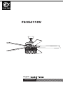
Parrot Uncle F6354110V Guide d'installation
- Taper
- Guide d'installation

F6354110V
www.parrotuncle.com
English / E spañol / Françaish

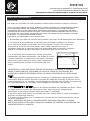
Sicherheit information
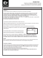
TECHNICAL INFORMATION
SKU
F6354110V
110-120V AC 55W 3*E12 MAX.40W(EXCLUDE)
light
F6354110V
WARNING: SHUT POWER OFF AT FUSE OR CIRCUIT BREAKER
Installation & Operating Instructions for the
Parrotuncle Owner's Installation ,Manual

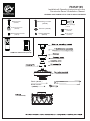
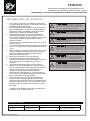
Wood screws
(4PCS)
Plastic wire nut
(3 PCS)
Blade bracket screws
(1PCS)
Mounting screws
(2 PCS)
washer (2PCS)
spring washer
(2PCS)
(1PCS)
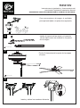
Balanced parts package
Blade screw
Blade
washer
(16PCS)
(16PCS)
4
Blade bracket
Blade (5PCS )
(5PCS)
F6354110V
WARNING: SHUT POWER OFF AT FUSE OR CIRCUIT BREAKER
Installation & Operating Instructions for the
Parrotuncle Owner's Installation ,Manual
REMOTE CONTROL(1PCS)
2h 4h 8h
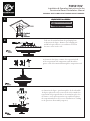
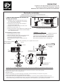
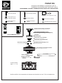
1
2
3

1
2
3
4
23
F6354110V
WARNING: SHUT POWER OFF AT FUSE OR CIRCUIT BREAKER
Installation & Operating Instructions for the
Parrotuncle Owner's Installation ,Manual
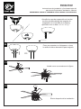
1

5
6
7
8
INSERT
BIUE
BLACK
WHITE
F6354110V
WARNING: SHUT POWER OFF AT FUSE OR CIRCUIT BREAKER
Installation & Operating Instructions for the
Parrotuncle Owner's Installation ,Manual

9
10
11
12
F6354110V
WARNING: SHUT POWER OFF AT FUSE OR CIRCUIT BREAKER
Installation & Operating Instructions for the
Parrotuncle Owner's Installation ,Manual
WARNING: SHUT POWER OFF AT FUSE OR CIRCUIT BREAKER
Installation & Operating Instructions for the
Parrotuncle Owner's Installation ,Manual

F6354110V
WARNING: SHUT POWER OFF AT FUSE OR CIRCUIT BREAKER
Installation & Operating Instructions for the
Parrotuncle Owner's Installation ,Manual
7. To Reduce the risk of shock, this fan must be installed
3. Electrical wire must meet all local and national
2. Do not use with solid state fans.
by removing fuse or switching off circuit breaker.
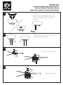
1. INSTALLING RECEIVER IN CEILING FAN
5. Maximum fan motor amps: 1.0.
6. Maximum light watts: 180 incandescent or ballast and LED.
4. Supply for fan must be 110/120 volt, 60Hz, 3.5A
1. WARNING: HIGH VOLTAGE! Disconnect power
INSTRUCTION OF INSTALLATION AND OPERATION
Remote controller
TRANSMITTER
(FIG.1)
Black receiver wire(TO MOTOR L)...Black fan wire
White receiver wire(TO MOTOR N)...White fan wire
White receiver wire(AC IN N)......White supply wire
Red/Black receiver wire(AC IN L)......Red/Black supply wire
supplied.
2.Remove ceiling fan canopy from the mounting bracket.
B. Installing receiver in fan CONNECT TO
1. Remove power from the circuit.
CAUTION: Ceiling Angle Shall Not Exceed 30 Degrees,
For Mounting Controller. Models GA012
4.Make connections as follows, using the wire nuts
3.Disconnect existing wiring between ceiling fan
and Supply in electrical junction box. Blue receiver wire(FOR LIGHT)...Blue light wire
(FIG.3)
ANTENNA PUT AT OUTSIDE
OF CANOPY BOX CAN GET
MORE OPERATION DISTANCE
LIGHT MUST KEEP AT THE
TURN ON POSITION
FAN MUST KEEP AT THE
HIGH SPEED POSITION
RECEIVER
CANOPY
FROM POWER SOURCE
AC 110~120 VOLT
60Hz 3.5AMPS.
Use wire connecting nuts supplied with the fan.
(FIG.2)
RECEIVER
A.Safety precautions
with a wall switch/control.
CANOPY
WHITE
INPUT
RED/BLACK
OUTPUT
ANT
INSERT
BIUE
BLACK
WHITE
ACN
INPUT
ACL
OUTPUT
ANT
RECEIVER
b.Lay the brown antenna wire on top of the receiver,and put the receiver into the mounting bracket.
If other fans or supply wires are different color, have this unit installed by qualified licensed electrician.
d.Restore power.
c.Reinstall the canopy on the mounting bracket.
a.Push all connected wires up into junction box.
e.Install 1.5 volt battery. (To prevent damage to transmitter, remove the battery if not used for a long time).
f. Store the transmitter away from excessive heat or humidity.
g.This remote control unit is equipped with roll code combinations. In order to prevent possible interference from or to
other remote units such as garage door openers, car alarm or security system. If you find that your fan and light kit go on
and off without using your remote control, simply change the code combination in your transmitter and receiver
RECEIVER
LENARN
CODE
LENARN CODE
CODE
COM
electrical code requirements.

F6354110V
WARNING: SHUT POWER OFF AT FUSE OR CIRCUIT BREAKER
Installation & Operating Instructions for the
Parrotuncle Owner's Installation ,Manual
.
.
.
authority to operate the equipment.
Rules. These limits are designed to provide reasonable protection against harmful interference in a residential installation. This
NOTE: This equipment has been tested and found to comply with the limits for a Class B digital, pursuant to Part 15 or the FCC
After the 1# and 2# remote control transmitters have been successfully learned, turn on the power of the two ceiling fans. At this time,
e.Good battery in the transmitter?
d.Light kit switch turned on?
c.Fan manual speed control in highest position?
b.Receiver wired correctly?
a.Power to receiver?
3.TROUBLE SHOOTING GUIDE
the 1# transmitter and the 2# transmitter can be used separately for one ceiling fan.
And so on, only one ceiling fan is powered on each time the corresponding transmitter learns.
If there are two or more ceiling fans installed in the same house, in order to prevent your ceiling fans from being affected by the
1 key-for fan low speed.
YOUR REMOTE NOW HAS FULL CONTROL OF THE FAN AND LIGHT.
OFF key-for fan off.
LIGHT key-for light on and off.
2 key-for fan medium speed.
Operating the buttons on the panel of the transmitter.
3 key -for fan high speed.
2. OPERATING TRANSMITTER:
Do NOT install this fan with variable speed wall
WARNING:
2hr , 4hr , 8hr button to set the FAN sleep timer
MODEL:GA012
remote control of the adjacent ceiling fans, first turn the switch in each remote control transmitter to the CODE(UP) position (see the
schematic diagram FIG1) Remarks: The standard state of the transmitter is in the down code COM.
(Power-off means you need to use a wall switch to shut down the power of the ceiling fan, if you do not have a wall switch,
please power off the whole room from the air circuit-breaker for each room)
After installing the remote control receiver on the ceiling fan
1: Turn on the power of the 1# ceiling fan receiver (the power of the 2# receiver is kept in a power-off state), within 30 seconds after
LR03 1.5V AAA
LR03 1.5V AAA
OPERATION DISTANCE 20 FEET
the fan power is turned on, press the LEARN button corresponding to the 1# transmitter, then The receiver will learn the transmitter code.
When the transmitter code is learned successfully, the light of the ceiling fans will flash twice, and then it can be used normally.
2: Turn on the power of the 2# ceiling fan receiver (the power of the 1# receiver is kept in a power-off state), within 30 seconds after
the fan power is turned on, press the LEARN button corresponding to the 2# transmitter, then The receiver will learn the transmitter code.
When the transmitter code is learned successfully, the light of the ceiling fans will flash twice, and then it can be used normally.
FCC Statement:
This device must accept any interference received, including interference that may cause undesired operation.
This device may not cause harmful interference.
This device complies with Part 15 of the FCC Rules. Operation is subject to the following two conditions.
Changes or modifications not expressly approved by the party responsible for compliance could void the user's
equipment generates, uses and can radiate radio frequency energy and, if not installed and used in accordance with the
instructions, may casue harmful interference to radio communications,
However, there is no guarantee that interference will not occur in a particular installation. If the equipment does cause harmful
interference to radio or television reception, which can be determined by turning the equipment off and on, the user is
encouraged to try to correct the interference by one or more of the following measures:
--- Reorient or relocate the receiving antenna.
--- Increase the separation between the equipment and receiver.
--- Connect the equipment into an outlet on a circuit different from that to which the receiver is connected.
--- Consult the dealer or an experienced radio/ TV technician for help.
control or wall-mounted dimmer switch. It will
permanently damage the fan's remote control
and cause the fan's function to fail.
NO Variable speed wall control NO Dimmer switch
TRANSMITTER
(FIG.1)
ACN
INPUT
ACL
OUTPUT
ANT
RECEIVER
LENARN
CODE
LENARN CODE
CODE
COM

F6354110V
WARNING: SHUT POWER OFF AT FUSE OR CIRCUIT BREAKER
Installation & Operating Instructions for the
Parrotuncle Owner's Installation ,Manual
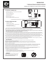
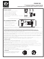
52"
11.8"
18.2"
5.9"
5.5"
52"
12.2"
26.5x4"or10"
11.2"
4.8"

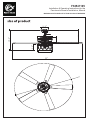
AFTER INSTALLATION
The fan blades have been adjusted in the factory to minimize any wobble
NOTE:CEILING FANS TEND TO MOVE DURING OPERATION DUE TO THE FACT THAT THEY
ARE MOUNTED ON A RUBBER CROMMET. IF THE FAN WAS MOUNTED RIGIDLY TO THE
CEILING, IT WOULD CAUSE EXCESS VIBRATION. MOVEMENT OF A FEW CENTIMENTERS
IS QUITE ACCEPTABLE AND DOES NOT SUGGEST ANY PROBLEM
WOBBLE”
TO REDUCE THE FAN WOBBLE: PLEASE CHECK THAT ALL SCREWS WHICH SECURED THE MOUNTING
BRACKET AND DOWNROD ARE SECURE.
BALANCING A WOBBLING CEILING FAN:
1.Check that all blade and blade arm screws are secure.
2.Most fan wobbling problems are caused when blade levels are unequal. Check this level by
selecting a point on the ceiling above the tip of one of the
blades. Measure this distance.Rotate the fan until the next blade is positioned for
measurement. Repeat for each blade. The distance deviation should be equal within
1/8"(0.32cm).
3.If the blade wobble is still noticeable, interchanging two
adjacent (side by side) blades can redistribute the weight
and possibly result in smoother operation. WARNING: TO REDUCE THE RISK OF PERSONAL
INJURY, DO NOT BEND THE BLADE ARM WHILE INSTALLING, BALANCING THE BLADES, OR
CLEANING THE FAN. DO NOT INSERT FOREIGN OBJECTS BETWEEN ROTATING FAN BLADES.
NOISE
When it is quiet(especially at night) you may hear occasional small noises. This is normal. Please allow a 24-
hour “breaking-in” period, most noises associated with a new fan disappear during the time.
CARE AND CLEANING
1.Periodic cleaning of your ceiling fan is the only maintenance required. Use a soft brush or lint free cloth to
avoid scratching the paint finish. Please make sure to turn o electricity power before you clean your fan
2.Do not use water when cleaning your ceiling fan. It could damage the motor or the blades
and create the possibility of an electrical shock.
3.Motor has permanently lubricated ball bearing. No need to oil
NOTE: MAKE SURE THE POWER IS OFF AT THE ELECTRICAL PANEL BOX BEFORE YOU
ATTEMPT ANY CLEANING OR REPAIRS.
F6354110V
WARNING: SHUT POWER OFF AT FUSE OR CIRCUIT BREAKER
Installation & Operating Instructions for the
Parrotuncle Owner's Installation ,Manual

F6354110V
www.parrotuncle.com
English / E spañol / Françaish

F6354110V
Instrucciones de instalación y funcionamiento del
ADVERTENCIA: CORTE LA CORRIENTE CON EL FUSIBLE O EL DISYUNTOR
parrotuncle Propietarios Instalación ,Manual
Información de seguridad
ADVERTENCIA:
Para reducir el riesgo de lesiones, los soportes de las
cuchillas (también conocidos como abrazaderas) no
deben doblarse durante ni después de la instalación. No
coloque ningún objeto en la trayectoria de las aspas.
ADVERTENCIA:
Retire los ataques de goma del motor situados en la
parte inferior del ventilador antes de montar las aspas
o probar el motor.
ADVERTENCIA:
Para evitar el riesgo de incendio o descarga eléctrica,
este ventilador no debe utilizarse con un variador de
velocidad de estado sólido.
ADVERTENCIA:
Para evitar el riesgo de descarga eléctrica, desconecte la
alimentación de la caja de seguridad principal antes de
realizar el cableado. Si considera que no tiene
suficientes conocimientos o experiencia en cableado
eléctrico, póngase en contacto con un electricista
autorizado.
ADVERTENCIA:
Los esquemas eléctricos son sólo de referencia. El uso
opcional de un tipo de luz debe ser listado y marcado
con este ventilador para su uso.
ADVERTENCIA:
Para reducir el riesgo de incendio, descarga eléctrica o
lesiones, conecte el aparato a una toma de corriente
que esté marcada como aceptada para ventiladores de
35 libras o menos. Está marcado y utilice los tornillos
suministrados con el enchufe.
Para reducir el riesgo de descarga eléctrica, debe
desconectarse la electricidad del interruptor de
protección o de la caja de seguridad antes de
arrancar.
Todo el cableado debe cumplir el Código Eléctrico
Nacional NASI/NFPA 70-1999 y las normativas
eléctricas locales. La instalación eléctrica debe ser
realizada por un electricista cualificado y autorizado.
La caja de conexiones y la estructura de soporte
deben estar montadas de forma segura y deben
poder transportarse de forma fiable con un peso de
15,9 kilos. Utilice únicamente cajas de conexión
marcadas con
"Aceptado para ventiladores con un peso igual o
inferior a 35 libras (15,9 kilos)".
El ventilador debe instalarse con una distancia
mínima de 2,1 m entre el borde posterior de las
aletas y el suelo.
No accione el interruptor de marcha atrás si las
aspas del ventilador están en movimiento. Debe
apagar el ventilador y detener las aspas antes de
invertir la dirección de las aspas.
No coloque ningún objeto en la trayectoria de las
alas.
Para evitar lesiones o daños al ventilador y a otros
objetos, tenga cuidado cuando trabaje o limpie el
ventilador.
Los diagramas eléctricos son sólo para referencia.
Los tipos de iluminación no suministrados con el
ventilador deben estar listados y marcados con el
modelo de válvula que se instalará para su uso. Los
interruptores deben ser interruptores UL de uso
general. Observe las instrucciones para una
instalación adecuada incluidas con los índices de
iluminación y los interruptores.
Una vez realizadas las conexiones eléctricas, se
debe dar la vuelta a la escalera de poda e
introducirla cuidadosamente en la caja de enchufes.
Los cables deben tenderse de forma que el
conductor de puesta a tierra y la cabeza del aparato
queden cerca del enchufe.
Antes de la instalación, compruebe todos los
tornillos de fijación y, si es necesario, apriételos.
1.
2.
3.
4.
5.
6.
7.
8.
9.
INFORMACIÓN TÉCNICA
110-120V AC
SKU Tensión nominal Potencia nominal (motor) Iluminación
F6354110V
55W 3*E12 MAX.40W(No incluido)

Tornillos para madera
(4pzas)
Tornillo de soporte de
la cuchilla (1pza)
Paquete de piezas equilibradas (1 pza)
Soporte de aspas
Aspa (5pzas)
(5PCS)
MANDO A DISTANCIA(1pza)
2h 4h 8h
1
2
3
F6354110V
Instrucciones de instalación y funcionamiento del
ADVERTENCIA: CORTE LA CORRIENTE CON EL FUSIBLE O EL DISYUNTOR
parrotuncle Propietarios Instalación ,Manual
Tuerca de alambre de
plástico (3pzas)
Tornillos de montaje
(2pzas)
Arandela (2pzas)
Arandela elástica
(2pzas)
Tornillo de la cuchilla
(16pzas)
Arandela de la cuchilla
(16pzas)
Soporte de montaje deslizante
Conjunto bola/vástago de 4"
Conjunto bola/vástago de 10" (en espera)
Tejadillo
Tapa del tejadillo
Cubierta de acoplamiento
Pin de bloqueo "R"
Eje colgante
Conjunto motor-ventilador
Kit de luz
Compruebe si los accesorios anteriores están completos o no. Sí, e instálelos.

1
2
3
4
Extraiga el ventilador principal de la caja
de embalaje, como se muestra en la figura.
Retire el pasador de suspensión y el pasador
de bloqueo R, y utilice undestornillador para
aflojar los dos tornillos laterales.
Como se muestra en la figura, retire la bola de
suspensión de la varilla de suspensión y paseel
cable de alimentación del ventilador principal a
través dela varilla de suspensión.
23
Como se muestra en la figura, pase por la varilla de
bloqueo y el pasador de bloqueo R apriete los dos
tornillos laterales de forma que la varilla de suspensi
ón quede perpendicular al ventilador principal. varilla
de suspensión quede perpendicular al ventilador
principal, coloque la cubierta decorativa y la copa de
suspensión, luego apriete la varilla de suspensión.
cubierta decorativa y la copa de suspensión, luego
apriete los tornillos de la bola de suspensión
(invierta la instalación según la secuencia de
desmontaje anterior)
1
F6354110V
Instrucciones de instalación y funcionamiento del
ADVERTENCIA: CORTE LA CORRIENTE CON EL FUSIBLE O EL DISYUNTOR
parrotuncle Propietarios Instalación ,Manual
Fijación del ventilador a la caja eléctrica
ADVERTENCIA: Para reducir el riesgode incendio,descarga
eléctrica o personal de 35 lbs.(15.9kg) o menos, "y utilice
los tornillos provistos con la caja de salida.
NOTA: El soporte de montaje(A) está diseñado para deslizarse
en su lugar en una caja de salida con los tornillos de la caja de
salida(LL).
Destornillador Phillins
Destornillador Phillins
Destornillador Phillins
Caja de salida
Soporte de montaje
Arandelas
Tornillo autorroscante

5
6
7
8
Instale el soporte de las aspas y el conector
de las aspas como se muestra en los pasos
de la imagen.
Fije los 5 elementos del soporte de las aspas
al motor
Como se muestra en la imagen, el ventilador
principal está fijado a la placa de suspensión,
IINSERTAR
AZUL
NEGRO
BLANCO
Instale y cablee los mandos a distancia
F6354110V
Instrucciones de instalación y funcionamiento del
ADVERTENCIA: CORTE LA CORRIENTE CON EL FUSIBLE O EL DISYUNTOR
parrotuncle Propietarios Instalación ,Manual
Destornillador Phillins
Destornillador Phillins

9
10
11
12
Atornille la copa de suspensión en los dos
tornillos situados debajo del soporte de
suspensión en el sentido de la flecha y
apriételos con un des
Como se muestra en el diagrama, coloca
la anilla de hierro decorativa para colgarlo.
Instale como se muestra en la figura.
Efecto después de la instalación
F6354110V
Instrucciones de instalación y funcionamiento del
ADVERTENCIA: CORTE LA CORRIENTE CON EL FUSIBLE O EL DISYUNTOR
parrotuncle Propietarios Instalación ,Manual
Destornillador Phillins

F6354110V
Instrucciones de instalación y funcionamiento del
ADVERTENCIA: CORTE LA CORRIENTE CON EL FUSIBLE O EL DISYUNTOR
parrotuncle Propietarios Instalación ,Manual
1.
INSTALACIÓN DEL RECEPTOR EN EL
VENTILADOR DE TECHO
1. ADVERTENCIA: ¡ALTA TENSIÓN! Desconecte la alimentación
quitando el fusible o desconectando el disyuntor.
2. No utilizar con ventiladores de estado sólido.
3. El cable eléctrico debe cumplir con todos los requisitos de
los códigos eléctricos locales y nacionales.
4. El suministro para el ventilador debe ser de 110/120 voltios,
60 Hz, 3,5 A.
5. Amperios máximos del motor del ventilador: 1,0.
6. Vatios de luz máximos: 180 incandescentes o balasto y LED.
7. Para reducir el riesgo de descarga eléctrica, este ventilador
debe instalarse con un interruptor/mando de pared.
INFORMACIÓN GENERAL
Mando a distancia
TRANSMISOR
(FIG.1)
B. Instalación del receptor en el ventilador CONECTAR A CONECTAR A Cable
1. Quite la corriente del circuito.
2.Retire la campana del ventilador de techo del soporte de
montaje.
3.Desconecte el cableado existente entre el ventilador de
techo y el suministro en la caja de conexiones eléctricas.
4.Haga las conexiones como se indica a continuación,
utilizando las tuercas para cables suministradas.
ATENCIÓN: El ángulo del techo no debe superar los 30 grados,
Para el controlador de montaje, modelo GA012
(FIG.3)
ANTENA EXTERIOR MÁS
TEJADILLO CAJA FUNCIONAMIENTO
PUEDE CONSEGUIR DISTANCIA
LA LUZ DEBE MANTENERSE EN POSICIÓN
VENTILADOR DEBE MANTENERSE A ALTA VELOCIDAD
RECEPTOR
Marquesina
Utilice las tuercas de conexión suministradas con el ventilador
(FIG.2)
RECEPTOR
A.Precauciones de seguridad
Toldo
BLANCO
ENTRADA
ROJO/NEGRO
SALIDA
ANT
ENCHUFE
AZUL
NEGRO
BLANCO
ACN
ENTRADA
ACL
SALIDA
ANT
RECEPTOR
RECEIVER
LENARN
CODE
LENARN CODE
CODE
COM
Cable verde del ventilador .... Cable desnudo de alimentación
Cable receptor rojo o negro (AC IN L).... Cable de alimentación rojo o negro
Cable receptor blanco (AC IN N)....Cable de alimentación blanco
Cable blanco del receptor (AL MOTOR N)....Cable blanco del ventilador
Cable negro del receptor (AL MOTOR L)....Cable negro del ventilador
Cable azul del receptor (para la luz) ....Cable azul de la luz
DE UNA FUENTE DE
ALIMENTACIÓN AC
110- 120 VOLT 60Hz
3.5AMPS.
ñ

F6354110V
Instrucciones de instalación y funcionamiento del
ADVERTENCIA: CORTE LA CORRIENTE CON EL FUSIBLE O EL DISYUNTOR
parrotuncle Propietarios Instalación ,Manual
a.¿Poder al receptor?
b.Receptor conectado correctamente?
c.¿Control de velocidad manual del ventilador
en la posición más alta?
d.Interruptor de kit de luz encendido?
e.¿Buena batería en el transmisor?
GUÍA PARA RESOLVER PROBLEMAS
SU CONTROL REMOTO AHORA TIENE EL CONTROL TOTAL DEL VENTILADOR Y LA LUZ.
Transmisor operativo:
Operando los botones en el panel del transmisor.
3 Key -para ventilador de alta velocidad.
2 llave para ventilador de velocidad media.
1 llave para ventilador de baja velocidad.
Fuera de la llave para el ventilador apagado.
Ligera llave para la luz encendida y apagada.
Botón de 2 horas, 4 horas, 8 horas para configurar el temporizador de
sueño del ventilador
LR03 1.5V AAA
LR03 1.5V AAA
MODELO: GA012
DISTANCIA DE OPERACIÓN 20 PIES
Si hay dos o más ventiladores de techo instalados en la misma casa, para evitar que sus ventiladores de techo se vean afectados por el
control remoto de los ventiladores de techo adyacentes, primero gire el interruptor en cada transmisor de control remoto a la posición del código
(arriba) (consulte la
Diagrama esquemático Fig1) Observaciones: El estado estándar del transmisor está en el código descendente com.
(Aperando significa que debe usar un interruptor de pared para apagar la alimentación del ventilador de techo, si no
tiene un interruptor de pared, apagar toda la habitación desde el descremador de circuito de aire para cada habitación)
Después de instalar el receptor de control remoto en el ventilador de techo
1: Encienda la potencia del receptor del ventilador de techo 1# (la potencia del receptor 2# se mantiene en un estado de apagado), dentro de los 30
segundos después de que se enciende la alimentación del ventilador, presione el botón de aprendizaje correspondiente al 1 # Transmisor, luego el
receptor aprenderá el código del transmisor. Cuando el código del transmisor se aprende con éxito, la luz de los ventiladores del techo parpadeará
dos veces, y luego se puede usar normalmente.
2: Encienda la potencia del receptor del ventilador de techo de 2# (la potencia del receptor 1# se mantiene en un estado de apagado), dentro de los
30 segundos después de que se enciende la alimentación del ventilador, presione el botón de aprendizaje correspondiente a los 2 # Transmisor,
luego el receptor aprenderá el código del transmisor. Cuando el código del transmisor se aprende con éxito, la luz de los ventiladores del techo
parpadeará dos veces, y luego se puede usar normalmente.
Y así sucesivamente, solo un ventilador de techo se enciende cada vez que el transmisor correspondiente aprende.
Después de que los transmisores de control remoto 1# y 2# se hayan aprendido con éxito, encienda la potencia de los dos ventiladores de techo. En
este momento, el transmisor 1# y el transmisor 2# se pueden usar por separado para un ventilador de techo.
Declaración de FCC:
Este dispositivo cumple con la Parte 15 de las Reglas de la FCC. La operación está sujeta a las siguientes dos condiciones.
Este dispositivo no puede causar interferencias perjudiciales.
Este dispositivo debe aceptar cualquier interferencia recibida, incluida la interferencia que pueda causar una operación no deseada.
Cambios o modificaciones no expresamente aprobadas por la parte responsable del cumplimiento podría anular el de los usuarios
autoridad para operar el equipo.
Nota: Este equipo ha sido probado y encontrado que cumple con los límites para una clase B digital, de conformidad con la Parte 15 o la FCC
Normas. Estos límites están diseñados para proporcionar una protección razonable contra la interferencia dañina en una instalación residencial.
Este equipo genera, usa y puede irradiar energía de radiofrecuencia y, si no se instala y se usa de acuerdo con el
Instrucciones, que la interferencia perjudicial para la radio a las comunicaciones de radio,
Sin embargo, no hay garantía de que la interferencia no ocurra en una instalación particular. Si el equipo causa una interferencia dañina a la
recepción de radio o televisión, que se puede determinar apagando y encendido, el usuario está
Alentado a tratar de corregir la interferencia por una o más de las siguientes medidas:
--- Reorientar o reubicar la antena receptora.
--- Aumente la separación entre el equipo y el receptor.
--- Conecte el equipo en una salida en un circuito diferente al del que está conectado el receptor.
--- Consulte al concesionario o un técnico experimentado de radio/ televisión para obtener ayuda.
ADVERTENCIA:
No instale este ventilador con pared de velocidad variable
Control o interruptor de atenuador montado en la pared. Va a
dañar permanentemente el control remoto del ventilador
y hacer que la función del ventilador falle.
Sin control de la pared de
velocidad variable
Sin interruptor de atenuación
TRANSMITTER
(FIG.1)
ACN
INPUT
ACL
OUTPUT
ANT
RECEIVER
LENARN
CODE
LENARN CODE
CODE
COM

52"
11.8"
18.2"
5.9"
5.5"
52"
12.2"
26.5x4"or10"
11.2"
4.8"
F6354110V
Instrucciones de instalación y funcionamiento del
ADVERTENCIA: CORTE LA CORRIENTE CON EL FUSIBLE O EL DISYUNTOR
parrotuncle Propietarios Instalación ,Manual
dimensión del producto

F6354110V
Instrucciones de instalación y funcionamiento del
ADVERTENCIA: CORTE LA CORRIENTE CON EL FUSIBLE O EL DISYUNTOR
parrotuncle Propietarios Instalación ,Manual
DESPUÉS DE LA INSTALACIÓN
OSCILACIÓN"
Las aspas del ventilador han sido ajustadas en fábrica para minimizar cualquier oscilación.
NOTA: LOS VENTILADORES DE TECHO TIENDEN A MOVERSE DURANTE SU FUNCIONAMIENTO PORQUE
ESTÁN MONTADOS SOBRE UNA ARANDELA DE GOMA. SI EL VENTILADOR ESTUVIERA MONTADO
RÍGIDAMENTE EN EL TECHO, PROVOCARÍA VIBRACIONES EXCESIVAS. UN MOVIMIENTO DE POCOS
CENTÍMETROS ES PERFECTAMENTE ACEPTABLE Y NO PLANTEA NINGÚN PROBLEMA.PARA REDUCIR LA
OSCILACIÓN DEL VENTILADOR: COMPRUEBE QUE TODOS LOS TORNILLOS QUE FIJARON EL MONTAJE
EL SOPORTE Y LA VARILLA ESTÁN BIEN FIJADOS.
EQUILIBRAR UN VENTILADOR DE TECHO OSCILANTE:
1. Compruebe que todos los tornillos de las aspas y del brazo de las aspas están bien apretados.
2. La mayoría de los problemas de oscilación del ventilador se deben a un desnivel
en el nivel de las aspas. Compruebe este nivel eligiendo un punto en el techo por
encima de la punta de una de las aspas. aspas. Mida esta distancia. Gire el
ventilador hasta que el siguiente aspa esté posicionada para la medición. medición.
Repita el procedimiento para cada aspa. La distancia debe ser de 0,32 cm.
3. si la oscilación de las aspas sigue siendo perceptible,
intercambiar dos aspas adyacentes (una al lado de la otra
) puede redistribuir el espacio entre las aspas. dos aspas
adyacentes (una al lado de la otra) puede redistribuir el
peso y posiblemente permitir un funcionamiento más
suave.
ADVERTENCIA: PARA REDUCIR EL RIESGO DE LESIONES, NO DOBLE EL BRAZO DE LAS
ASPAS CUANDO INSTALE, EQUILIBRE LAS ASPAS O LIMPIE EL VENTILADOR. NO
INTRODUZCA OBJETOS EXTRAÑOS ENTRE LAS ASPAS GIRATORIAS DEL VENTILADOR.
RUIDO
Con tiempo tranquilo (especialmente por la noche), es posible que oiga pequeños ruidos
ocasionales. Esto es normal. Permita un período de rodaje de 24 horas; la mayoría de los
ruidos asociados con un ventilador nuevo desaparecen durante este período. La mayoría de
los ruidos asociados a un ventilador nuevo desaparecen durante este periodo.
7 MANTENIMIENTO Y LIMPIEZA
1. El único mantenimiento necesario es la limpieza periódica del ventilador de techo. Utilice
un cepillo suave o un paño sin pelusa para evitar rayar la pintura. Asegúrese de
desconectar el suministro eléctrico antes de limpiar su ventilador.
2. No utilice agua para limpiar el ventilador de techo. Podría dañar el motor o las aspas y
provocar una descarga eléctrica.
3. El motor está equipado con un rodamiento de bolas de lubricación permanente. No es
necesario engrasarlo.
NOTA: ASEGÚRESE DE QUE LA CORRIENTE ESTÁ DESCONECTADA EN EL CUADRO
ELÉCTRICO ANTES DE REALIZAR CUALQUIER TRABAJO DE LIMPIEZA O REPARACIÓN. NO
LIMPIE NI REPARE EL APARATO.
Botón de techo
La page est en cours de chargement...
La page est en cours de chargement...
La page est en cours de chargement...
La page est en cours de chargement...
La page est en cours de chargement...
La page est en cours de chargement...
La page est en cours de chargement...
La page est en cours de chargement...
La page est en cours de chargement...
La page est en cours de chargement...
La page est en cours de chargement...
-
 1
1
-
 2
2
-
 3
3
-
 4
4
-
 5
5
-
 6
6
-
 7
7
-
 8
8
-
 9
9
-
 10
10
-
 11
11
-
 12
12
-
 13
13
-
 14
14
-
 15
15
-
 16
16
-
 17
17
-
 18
18
-
 19
19
-
 20
20
-
 21
21
-
 22
22
-
 23
23
-
 24
24
-
 25
25
-
 26
26
-
 27
27
-
 28
28
-
 29
29
-
 30
30
-
 31
31


Parrot Uncle F6354110V Guide d'installation
- Taper
- Guide d'installation
dans d''autres langues
Documents connexes
-
Parrot Uncle F6351110V Guide d'installation
-
-
-
-
-
-
-
-
Parrot Uncle A563401CB Manuel utilisateur
-
Parrot Uncle A556201CH Manuel utilisateur
Autres documents
-
 Hinkley 980045 Manuel utilisateur
-
 Kichler Lighting 310204WCP Manuel utilisateur
-
Progress Lighting 93114646 B Guide d'installation
-
-
-
-
-
-

