Garland E20 Series Owner Instruction Manual
- Taper
- Owner Instruction Manual

Part # P125 Rev 2 (07/31/12) Page 1
Users are cautioned that maintenance and repairs must be performed by a Garland authorized service agent
using genuine Garland replacement parts. Garland will have no obligation with respect to any product that has been
improperly installed, adjusted, operated or not maintained in accordance with national and local codes or installation
instructions provided with the product, or any product that has its serial number defaced, obliterated or removed,
or which has been modified or repaired using unauthorized parts or by unauthorized service agents.
For a list of authorized service agents, please refer to the Garland web site at http://www.garland-group.com.
The information contained herein, (including design and parts specifications), may be superseded and is subject
to change without notice.
Part # P125 Rev 2 (07/31/12) © 2005 Garland Commercial Industries, Inc.
FOR YOUR SAFETY:
DO NOT STORE OR USE GASOLINE
OR OTHER FLAMMABLE VAPORS OR
LIQUIDS IN THE VICINITY OF
THIS OR ANY OTHER
APPLIANCE
WARNING:
IMPROPER INSTALLATION, ADJUSTMENT,
ALTERATION, SERVICE OR MAINTENANCE
CAN CAUSE PROPERTY DAMAGE, INJURY,
OR DEATH. READ THE INSTALLATION,
OPERATING AND MAINTENANCE
INSTRUCTIONS THOROUGHLY
BEFORE INSTALLING OR
SERVICING THIS EQUIPMENT
PLEASE READ ALL SECTIONS OF THIS MANUAL
AND RETAIN FOR FUTURE REFERENCE.
THIS PRODUCT HAS BEEN CERTIFIED AS
COMMERCIAL COOKING EQUIPMENT AND
MUST BE INSTALLED BY PROFESSIONAL
PERSONNEL AS SPECIFIED.
IN THE COMMONWEALTH OF MASSACHUSETTS
THIS PRODUCT MUST BE INSTALLED BY A
LICENSED PLUMBER OR GAS FITTER. APPROVAL
NUMBER: G-1-07-05-28
For Your Safety:
Post in a prominent location, instructions to be
followed in the event the user smells gas. This
information shall be obtained by consulting
your local gas supplier.
INSTALLATION OPERATION
AND SERVICE MANUAL
G2000 SERIES GAS BAKE AND
ROAST DECK OVENS
Manufactured by:
Cleveland Range
1333 East 179
TH
Street
Cleveland, Ohio 44110
USA
Garland Commercial Ranges, LTD.
1177 Kamato Road,
Mississauga, Ontario L4W 1X4
CANADA
General Inquiries 1-905-624-0260
USA Sales, Parts and Service 1-800-424-2411
Canadian Sales 1-888-442-7526
Canada or USA Parts/Service 1-800-427-6668

Part # P125 Rev 2 (07/31/12)Page 2
IMPORTANT INFORMATION
WARNING:
This product contains chemicals known to the state of california to cause cancer and/or birth defects
or other reproductive harm. Installation and servicing of this product could expose you to airborne
particles of glass wool/ceramic fibers. Inhalation of airborne particles of glass wool/ceramic fibers
is known to the state of California to cause cancer.
Keep appliance area free and clear of combustibles.
Rights written notice
2012 ALL RIGHTS RESERVED. This manual and the text and images it contains may not be
modied in any way, by any means, without written permission from Garland Commercial
Ranges Ltd. .

Part # P125 Rev 2 (07/31/12) Page 3
TABLE OF CONTENTS
Important Information .................2
Dimensions And Specications,
G2000 Series ..........................4
OVEN SPECIFICATIONS .................5
General ......................................5
INTRODUCTION........................5
Garland Variety Ovens .......................5
INSTALLATION .........................6
Pre-Installation Instructions ..................6
Rating Plate ..................................6
Location of the Oven .........................6
Clearances ...................................6
Legs .........................................7
Assembly of Two-Section Oven ...............7
Installation of Oven Vent .....................7
Top Trim Installation .........................8
Ovens with Optional Light Feature ............8
Gas Connection-Single & Multiple Ovens ......8
Installation Of Oven Heat Deectors,
Corderite/Steel Hearths &
Inner Oven Linings ...........................9
Ventilation and Air Supply ....................9
Installation of a Direct Flue ...................9
Operation ............................10
Burn O – Deck Curing ......................10
User Guide – Timetable for Roasting .........11
User Guide – Timetable for Baking ...........13
Maintenance .........................14
Stainless Steel ..............................14
Oven Interior ...............................14
Cleaning of Oven Hearth ....................14

Part # P125 Rev 2 (07/31/12)Page 4
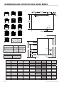
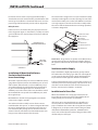
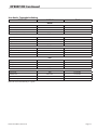
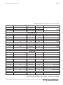
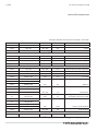
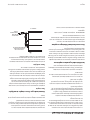
DIMENSIONS AND SPECIFICATIONS, G2000 SERIES
MODEL A: In (mm) B: In (mm) C: In (mm) D: In (mm) E: In (mm) F: In (mm) G: In (mm) Total BTU
G2071 50(1270) 58(1473) 40½(1664) 31(787) 40,000
G2072 58½(1270) 66½(1689) 31½(800) 49(1283) 22(559) 80,000
G2073 60(1524) 68(1727) 15½(394) 33(838) 50½(1283) 6(152) 120,000
G2121 55(1397) 63(1600) 40½(1664) 31(787) 40,000
G2122 60½(1537) 68½(1740) 23½(597) 46(1168) 14(356) 80,000
G2123 75(1905) 83(2018) 15½(394) 38(965) 60 ½(1537) 6(152) 120,000
G2771 60(1524) 68(1727) 40½(1664) 50½(1283) 31(787) 50,000
G2772 62½(1587) 70½(1791) 15½(394) 25 ½(648) 43(1092) 53(1346) 6(152) 100,000
G2121-71 63½(1613) 71½(1816) 31½(800) 54(1372) 22(559) 80,000
G2121-72 65(1651) 73(1854) 15½(394) 38(965) 55½(1410) 6(152) 120,000
G2121-771 57½(1460) 65½(1664) 15½(394) 38(965) 48(1219) 6(152) 90,000
G2122-71 70(1778) 78(1981) 15½(394) 38(965) 60 ½(1537) 6(152) 120,000
G2071-771 60½(1537) 68½(1664) 23½(597) 41(1041) 51(1295) 14(356) 90,000
17"
(432mm)
G
C
D
E
F
BA
3/4" NPT
GAS INLET
55-1/4"
(1416mm)
10-5/8"
(280mm)
2"
(51mm)
1"
(25mm)
2-1/4"
(57mm)
3"
(76mm)
27-7/8"
(708mm)
2"
(51mm)
38-1/4"
(972mm)
All Models Natural Propane
Manifold
Operating Pressure
5.5" WC
(13.7 Mbar)
10.0" WC
(24.9 Mbar
Minimum
Supply Pressure
7.0" WC
(17.4 Mbar)
11.0" WC
(27.4 Mbar)
Combustible Wall Clearances
Sides Back
1” (25mm) 6” (152mm)
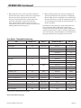
G2121-71
G2073
7B
7B
7B
12R
7B
G2121-771
G2071
7B
12R
12R
T7B
T7B
12R
G2122
G2771
G2072
7B
7B
12R
12R
T7B
7B
7B
T7B
T7B
12R
12R
12R
G2123
G2122-71
G2772
G2071-771
G2121-72
G2121
12R
7B
7B
12R
7B = 7" Bake
T7B = Twin 7" Bake
12R = 12" Roast

Part # P125 Rev 2 (07/31/12) Page 5
OVEN SPECIFICATIONS
General
Construction:
Ovens are of the sectional type with each section operating
independently. Sectional type with each section operating
independently. Sectional design makes it easy to add
additional sections as required. Heavy duty modular
construction minimizes the use of hard to clean screws and
bolts on the exterior of the oven. Cleaning is easier and more
complete. Sections are supported on heavy steel legs, which
are easily changed as sections are added. Oven legs are
standard equipment.
Bake Section:
Bake section interior is 42” x 32” x 7” each section. The ¾”
corderite deck is provided as standard equipment. A 12
gauge steel hearth may be substituted if specied before
placing order.
General Purpose Section:
Two compartments 42” x 32” x 7” each section. Each provided
with its own deck and door. Standard deck is ¾” thick
corderite. A 12 gauge hearth may be substituted if specied
before placing order.
Roast Sections:
The 12” roast interior is 42” x 32” x 12”. Interior of the 16”
sections is 42” x 32” x 16”. A 12 gauge steel hearth is provided
as standard for both 12” gauge steel hearth is provided as
standard for both 12” and 16” sections. A corderite deck is
available as an optional extra.
Burners:
Each oven is heated by two “U” shaped lance ported burners
ring directly on heavy steel tread plate between the burners
and the deck. In each oven section, a heavy duty throttling/
snap action gas thermostat controls burners to provide a
150º to 500º Fahrenheit temperature range aording low
temperature holding feature. Each section is further provide
with an independent ON/OFF gas valve and 100% safety
pilot system.
Venting:
Flue deector is provided to meet ventilation system
requirements. Internal ues connect for stacking.
Oven Door:
Oven door is engineered with precise balance and
exceptional durability. Door opens to full width of oven
cavity and to exact level of horizontal oven deck for
unobstructed loading. Door will support tin excess of 250
pounds of load.
INTRODUCTION
Garland Variety Ovens
The dependable line of Garland Variety Heavy Duty Bake and
Roast Ovens are designed for use where quality foods are
prepared in mass quantity. These ovens are ideal for hotels,
hospital, schools, larger cafeterias, dining rooms and all other
high production operations.
Basic Variety Oven sections are designed for stacking to
provide an innite choice of bake and roast combinations.
Independently operated oven sections with separate
controls, aord the advantage of cooking a variety of
products at dierence temperatures at the same time.
GARLAND’S new Variety Oven line was designed to give
years of dependable service. Engineering excellence assures
customers of quality construction and products that perform
well. This addition to the GARLAND family of commercial
cooking products is testimony to the dedicated eorts of
our employees, who have pride in their workmanship and
therefore, build better products that reect this spirit.

Part # P125 Rev 2 (07/31/12)Page 6
Pre-Installation Instructions
The importance of proper installation of commercial
gas cooking equipment cannot be over stressed. Proper
performance of the equipment is dependent, in great part,
on the compliance of the installation with the manufacturer’s
specications. The installation and connections must comply
with local codes, or in the absence of local codes, with
CAN/CGA-B149 installation code or with the National Fuel
Gas code, ANSI Z 223.1/NFPA No. 54 – latest edition.
All burner adjustments and setting shall be made by a
qualied gas technician.
A. The type of gas for which the unit is equipped is stamp on
the date plate located behind lower front panel. Connect
a unit stamped “NAT” only to natural gas; connect a unit
stamped “PRO” only to propane gas.
B. If it is a new installation, have gas authorities check meter
size and piping to assure that the unit is supplied with
sucient amount of gas pressure required to operate the
unit.
C. If it is additional or replacement equipment, have gas
authorities check pressure to make certain that existing
meter and piping will supply fuel at the unit with not
more than 1/2” water column pressure drop.
INSTALLATION
Rating Plate
When corresponding with the factory or your local
authorized factory service center regarding service problems
or replacement parts, be sure to refer to the particular unit
by the correct model number (including the prex and sux
letters and numbers) and the warranty serial number. The
rating plate axed to the unit contains this information.
We suggest installation, maintenance and repairs should be
performed by your local authorized service agency listed in
your information manual pamphlet.
In the event you have any questions concerning the
installation, use, care or service of the product, write or call
our Product Service Department.
This product must be installed by professional personnel as
specied. Garland/U.S. Range products are not approved or
authorized for home or residential use, but are intended for
commercial applications only. Garland / U.S. Range will not
provide service, warranty, maintenance or support of any
kind other than in commercial applications.
Location of the Oven
Appliances shall be installed in a location in which the
facilities for ventilation permit satisfactory combustion of gas
and proper venting. Appliances shall be located so as not to
interfere with proper circulation of air within the conned
space. When buildings are so tight that normal inltration
does not provide the necessary air, outside air shall be
introduced.
Clearances
NOTE: Unit must be installed with no less than
6 inches (152mm) clearance from combustible construction
at both sides and rear. Installation to non-combustible
construction is (0”) clearance at both sides and rear. The unit
suitable for installation on combustible oors.
INTRODUCTION Continued

Part # P125 Rev 2 (07/31/12) Page 7
D. Obtain a pressure regulator to deliver gas at the pressure
shown on the rating plate. This unit is supplied with a
pressure regulator.
NOTE: When checking pressure be sure that all other
equipment on the same gas line is on. A pressure regulator
is supplied with GARLAND equipped. Set regulator to deliver
gas at pressure shown on rating plate. Installation must
conform with the national Fuel Gas Code ANSI Z223.1-Latest
Edition/NFPA No. 54-Latest Edition and/or local code to
assure safe and ecient operation.
NOTE: In Canada, the installation shall be in accordance
with CAN/CGA-B149.1 NATURAL GAS INSTALLATION CODE
or CAN/CGA-B149.2 PROPANE GAS INSTALLATION CODE and
local codes where applicable.
NOTE: The appliance and its individual shut-o (supplied by
others) must be disconnected from the gas supply piping
system during any pressure testing of that system at test
pressures in excess of 1/2 PSI (3.45kPa).
The appliance must be isolated from the gas supply piping
by closing its individual manual shut-o (supplied by others)
during any pressure testing of the gas supply piping system
at test pressures equal to or less than ½ PSI (3.45 kPa).
NOTE: Adequate clearance must be provided for servicing
and proper operation.
Legs
Raise the front of the oven. Position the legs inside the front
corners of the angle from frame. Start each bolt, threading
them into the weld nuts on the angle base frame. Four (4)
bolts and four (4) washers must be used to secure each leg in
place. Tighten the bolts evenly and securely. Raise and block
the rear of the oven and fasten the rear legs as above.
Assembly of Two-Section Oven
Before raising the upper section into its proper position,
check at the rear centre of the underside of the upper section
(as per drawing). The rectangular ue opening should be
open. If the ue opening is covered, remove the “Bottom Flue
cover Patch” and discard.
Bottom Flue
Cover Patch
Be sure that the top trim cap (stainless steel angle iron square
frame) is not installed on the lower or middle ovens. Place
2 x 4’s on the top of the lower or middle ovens. Place
2 x 4’s on the top of the lower oven section – about 6” in from
each side, running front to back. Raise the top section and
position it on the 2 x 4’s so that the front, rear and sides of the
top section line up with the lower section. The internal upper
ue will telescope over the internal lower ue.
The upper oven section bottom frame will telescope or
capture the bottom unit. It is not necessary to bolt the
section together.
Installation of Oven Vent
1. The most ecient system for ventilating this oven is
a properly designed hood. This hood should extend
6 inches beyond the front and sides of the oven and
the back, unless oven is against a re resistive wall. The
design of the hood should be such that it will not pull the
heat too rapidly out of the oven through the ue.
INSTALLATION Continued

Part # P125 Rev 2 (07/31/12)Page 8
INSTALLATION Continued
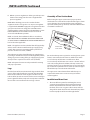
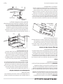
The ue deector provided (Fig. 1) should be installed
to prevent this situation from occurring. Set the ue
deector in place over the anges of the internal ue. The
sloped opening of the ue deector will be to the front.
Fasten the side anges of the ue deector by means of
the sheet metal screws provided.
2. If the oven must be connected to a direct ue, this ue
should rise 10 feet above the roof of the building in
which the oven is installed, or 10 feet above any portion
of a building within a horizontal distance of 10 feet. The
draft hood provided must be installed. In addition, it is
necessary that barometric draft control (available from
Garland) be installed. (See Fig. 2)
The draft hood should be positioned with its vertical
bottom opening over the vertical anges of the oven
ue. The anges of the draft hood should be to the sides
and front. Fasten the draft hood to the oven by means of
sheet metal screws through the holes on each side ange
at the bottom of the draft hood.
The barometric damper must be installed to conform
with the applicable instructions packed with the
barometric damper. The relief opening of the barometric
damper should be located so that it is not obstructed by
any part of the oven or adjacent constructions.
The barometric damper should be installed as close to
the draft hood as possible, while conforming to code
requirements.
Under no circumstances should ue pipe with less than
a 6 inch diameter be installed between the oven and the
chimney termination.
If more than one appliance is connected to a single
vent, the vent shall be sized in accordance with sound
engineering principles.
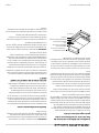
FLUE DEFLECTOR
FIGURE 1
BAROMETRIC
DAMPER
DRAFT HOOD
FIGURE 2
Top Trim Installation
The front of the top trim is formed as a channel. Open the
upper oven door. Hold the top trim with the rear raised
and slide its lower ange into position in the oven opening
between the right and the left front columns. Lower the top
trim into position over the oven top. The top trim does not
require that it be bolted or fastened into position.
Ovens with Optional Light Feature
Important: This appliance must be electrically grounded in
accordance with local codes, or in the absence of local codes,
the Canadian Electrical Code C22.1 or with the National
electrical code ANSI/NFPA No. 70 (latest edition whichever is
applicable.
Warning – Electric Grounding Instructions
This appliance is equipped with a three prong (grounding)
plug for your protection against shock hazard and must be
plugged into a properly grounded three prong receptacle.
Do not cut or remove the grounding prong from this plug.
A wiring diagram is attached to the back of the unit.
Gas Connection-Single & Multiple Ovens
Single Oven
Install the pressure regulator (supplied) with the outlet
(arrowhead) connected to the tail pipe. The ¾” N.P.T. inlet of
the pressure regulator must be considered in piping the gas
supply. Each group of ovens should be supplied (by others)
with an in-line manual shut o valve.

Part # P125 Rev 2 (07/31/12) Page 9
INSTALLATION Continued
Each stack of oven sections may be piped individually as
described above. Each stack should be provided with its own
manual gas shut o valve as described. If the ovens are to be
piped using all of the materials provide, refer to diagram “A”.
Multiple Ovens
If the ovens are to be stacked, they may be piped as shown
in the diagram “A”. Again, as stated above, a readily accessible
gas shut o valve of an approved type should be installed in
the supply line.
PRESSURE
REGULATOR
GAS
SUPPLY
STACKING PIPE KIT
FOR COMBINATION OVEN
DIAGRAM "A"
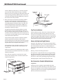
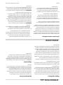
Installation Of Oven Heat Deectors,
Corderite/Steel Hearths &
Inner Oven Linings
All models require that two part oven heat deectors (heavy
gauge diamond plate) and two heat deector pans (in oven
with corderite deck material) or one heat deector pan (in
oven with steel deck), be installed above the oven burners
to give even heat throughout the oven. Install the heat
deector pan(s) in the centre of the oven deck frame. Install
the heat deectors on top of the heat deector pans, with
the rough side up.
Both deectors should be brought together to make the
centre seam as tight as possible.
The corderite hearth assembly consists of two sections
installed within deck spacers, as shown in Diagram “B”. Install
the two (2) aluminized inner oven linings in the front and
rear channels by rst placing the rear of each in each rear
channel. Then raise the front of each aluminized inner oven
linings over and down into the front channels.
The steel hearth is designed as a one-piece welded assembly
and will pass through the oven door opening. The rear of the
steel hearth assembly rests on the heat deectors inside the
rear angle support. Centre the steel hearth assembly within
the oven. Install the aluminized inner oven linings provided,
as shown in Diagram “B”.
INNER OVEN LINING
RIGHT AND LEFT
DECK SPACER
RIGHT, REAR AND LEFT
DECK
HEAT DEFLECTOR
HEAT DEFLECTOR PAN (2)
DECK FRAME (Ref.)
DIAGRAM "B"
IMPORTANT: All gas burners and pilots need sucient air to
operate and large objects should not be placed in front of
this appliance which would obstruct the air ow through the
front.
Ventilation and Air Supply
Proper ventilation is highly important for good operation.
The ideal method of venting a gas deck oven is through the
use of a properly designed canopy which should extend 6”
beyond all sides of the appliance and 6’6” from the oor.
A strong exhaust fan will create a vacuum in the room. For an
exhaust system vent to work properly, replacement air must
enter the room in which the vent is located. For proper air
balance, contact your local H.V.A.C. contractor.
Installation of a Direct Flue
When the installation of a canopy type exhaust hood is
impossible, the oven may be direct vented. Before direct
venting check your local codes on ventilation.
If the unit is to be connected directly to a direct ue, it is
necessary that an 8” draft diverter be installed to insure
proper ventilation. First remove the canopy diverter (shown
in Diagram “A”), and replace with a Garland designed down
draft diverter (P/N1056497 painted or 1056496 stainless
steel). Connect directly to the Garland designed down draft
diverter with your stove pipe.

Part # P125 Rev 2 (07/31/12)Page 10
OPERATION
Once the equipment has been installed and tested by
qualied professional personnel, the oven is ready for
operation. If the pilot is not lit, proceed as follows:
1. Check the oven gas valve. It should be in the “OFF”
position. If not, turn this valve to the “OFF” position.
2. Remove the lower front panel by turning the special self-
retaining fasteners.
3. Ignition of the pilot is made by passing a lighted taper
through the access hole in the front air shield, or by
removing this shield while pressing in and holding the
red reset button of the oven safety valve. This button is
reached through the access hole in the centre section of
the side control panel. Release the red button after the
pilot has been lit, approximately 45 seconds. If the pilot
does not remain lit, repeat after waiting 5 minutes.
4. After the oven pilot is lit, replace the front air shield and
lower front panel.
Burn O – Deck Curing
Many of the parts used in the oven have a thin protective
oil covering. This oil should be burned o before the oven
is used for production of food. The following burn o
procedure will also service to “cure” the oven hearth. If the
curing procedure is not followed, there is a potential for the
deck material to crack.
Turn the oven thermostat dial back to the 300°F setting
and run the oven at this temperature for at least an hour.
Repeat at 400°F and 500°F. the total “curing” process is
accomplished in a 3 hour period of time.
The oven may now be shut down by turning the gas control
valve to the “OFF” position and turning the thermostat back
to its lowest setting.
NOTE: You cannot turn the oven o just by turning the oven
thermostat down. You must turn the gas valve to the “OFF”
position.
It will not be necessary to extinguish the oven pilot unless
the oven is to remain unused for a long period of time.
After the hearth is “cured”, the oven is ready for operation.
1. If the oven pilot has been extinguished, go through steps
1 through 4, as previously listed.
2. All models that have the corderite hearths should be
preheated for no less than one (1) hour. This will bring
the oven interior to the desired temperature and will
provide time for the hearth and the oven interior surfaces
to absorb and store heat required for optimum oven
performance. All models that have steel hearths will
require approximately 25 minutes to preheat.
3. After preheating, the oven is ready for use.
4. Distribute the load evenly on the deck. Space pans
equally from each other and the side of the oven.
5. Planning will avoid unbalanced baking as a result of
adding product after loading goods have started to bake.
6. Do not open door unnecessarily. Repositioning of
product is not required in most cases.
NOTE: Each oven has been factory tested and adjusted prior
to shipment. It may be necessary to further adjust the oven
as part of a proper installation. Such adjustments are the
responsibility of the installer.
Adjustments are not considered defects in material and
workmanship, and they are not covered under the original
equipment warranty.
Do Not Undersize The Vent Pipe! This can cause resistance
to ow and impede good eciency.
INSTALLATION Continued

Part # P125 Rev 2 (07/31/12) Page 11
7. When using the G-2771 or the G-2772 General Purpose
Oven for the same product, load the upper compartment
rst, then the lower compartment. It is normal for
the upper compartment (in this specic model only)
to be 30°F to 60°F lower in temperature than the
lower chamber. When product is done in the lower
compartment, remove same. Check upper compartment,
allowing additional time if required.
8. Before loading, preheat oven at least 25°F higher than
desired temperature for Strong bottoms and Light tops.
When loading of oven is completed, turn control down to
desired temperature. For products requiring Strong tops,
turn oven temperature control up 25°F for the nal 8 – 10
minutes of baking.
The following is intended only as guide. Temperature and
time requirements will be aected by specic recipes,
varying methods of food preparation, quality of ingredients
and personal preferences, as well as numerous other factors.
Your own techniques, coupled with the recommendations of
this guide, will permit you to establish your own chart.
OPERATION Continued
User Guide – Timetable for Roasting
CUT WEIGHT (LB.) OVEN ° F INTERNAL TEMP. °F MIN./LB.
Beef
Standing Rib 6-8 300°-235° 140° Rare 23-25
Standing Rib (7 Rib) 20-25 300° 160° Rare 27-30
125° Rare 11
140° Med 12
150° Well 13
Round (Rump & Shank O ) 50 250° 140° Med 12
Rolled Rib 5-7 300°-350° 140° Rare 32
160° Med 38
170° Well 48
Rib Eye 4-6 350° 140° Rare 18-20
160° Med 20-22
170° Well 22-24
Tenderloin (1/2) 2-3 425° 140° Rare 45-60
Whole 4-6 425° 140° Rare 45-60
Rolled Rump (High Quality) 4-6 300°-325° 150°-170° 35-40
Sirloin Tip (High Quality) 3 1/2-4 300°-325° 150°-170° 35-40
Veil
Leg 5-8 300°-325° 170° 23-35
Loin 4-6 300°-325° 170° 30-35
Rib (Rack) 3-5 300°-325° 170° 35-40
Rolled Shoulder 4-6 300°-325° 170° 40-45
Note: This list is intended only as a guide
Chart continued on next page

Part # P125 Rev 2 (07/31/12)Page 12
OPERATION Continued
CUT WEIGHT (LB.) OVEN ° F INTERNAL TEMP. °F MIN./LB.
Lamb
Leg 5-8 300°-325° 175°-180° 30-35
Shoulder 4-6 300°-325° 175°-180° 30-35
Rolled 3-5 300°-325° 175°-180° 40-45
Cushion 3-5 300°-325° 175°-180° 30-35
Pork, (Fresh)
Loin Centre 3-5 325°-350° 170° 30-35
Half 3-5 325°-350° 170° 35-40
Blade/Sirlion 3-4 325°-350° 170° 40-45
Picnic Shoulder 5-8 325°-350° 185° 30-35
Rolled 3-5 325°-350° 185° 40-45
Cushion Style 3-5 325°-350° 185° 35-40
Boston Shoulder 4-6 325°-350° 185° 45-50
Leg (Fresh Ham)
Whole -Bone In 10-14 325°-350° 185° 25-30
Whole -Boneless 7-8 325°-350° 185° 40-45
Half - Bone In 5-7 325°-350° 185° 40-45
Pork, (Smoked)
Ham (Uncooked)
Whole 10-14 300°-325° 160° 18-20
Half 5-7 300°-325° 160° 22-25
Shank/Butt 3-4 300°-325° 160° 35-40
Ham (Cooked)
Whole 10-14 325° 130° 15
Half 5-7 325° 130° 18-24
Picnic Shoulder 3-5 300°-325° 170° 35
Shoulder Roll 2-3 300°-325° 170° 35-40
Canadian Style Bacon 2-4 300°-325° 160° 35-40
Poultry (All Not Stued)
Chicken-Roasters 2 1/2-3 325° 36
Turkeys 14-16 300° 22
25-30 350° 16
Ducks 4-5 325° 36
Note: This list is intended only as a guide
User Guide – Timetable for Roasting continued

Part # P125 Rev 2 (07/31/12) Page 13
OPERATION Continued
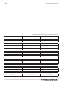
User Guide – Timetable for Baking
PRODUCT OVEN °F TIME
Breads
White Bread 375°-425° 30-40 Min.
Wheat Bread 375°-425° 30-40 Min.
Rye Bread 400° 40-60 Min.
Corn Bread (Individual) 375°-425° 25-30 Min.
Cakes
White Sheet 375° 30-35 Min.
Yellow Sheet 375° 30-35 Min.
Angel Food 400° 20-30 Min.
Devil’s Food 350° 20-30 Min.
Cookies
Sugar 375° 15 Min.
Chocolate Chip 375° 15 Min.
Butter 400° 10-15 Min.
Macroons 350° 20 Min.
Pies
Apple 400°-425° 50-60 Min.
Cherry 400°-425° 50-60 Min.
Pumpkin 375°-425° 30-40 Min.
Custard 375°-425° 30-40 Min.
Rolls
Clover Leaf 400° 15-20 Min.
Parkerhouse 400°-425° 15-20 Min.
Biscuits 425° 20 Min.
Danish Pastry 375° 20-30 Min.
Note: This list is intended only as a guide

Part # P125 Rev 2 (07/31/12)Page 14
MAINTENANCE
We suggest maintenance and repairs to be performed by an
GARLAND AUTHORIZED SERVICE AGENT. The listing provided
with your oven is titled “Maintenance and Repair Centres”.
Stainless Steel
For routine cleaning, just wash with a hot water and
detergent solution. Wash just a small area at a time or the
water will evaporate leaving the chemicals behind causing
streaking.
Rinse the washed area with a clean sponge dipped in a
sanitizing solution. Wash just a small area at a time or the
water will evaporate leaving the chemicals behind causing
streaking.
Rinse the washed area with a clean sponge dipped in a
sanitizing solution and wipe dry with a soft clean cloth
before it can dry.
Use a paste (of water and a mild scouring powder) if you
have to, but never rub against the grain. All stainless steel has
been polished in one direction. Rub with the polish lines to
preserve the original nish. Then thoroughly rinse as before.
To prevent ngerprints, there are several stainless steel
polishes on the market that leave an oily or waxy lm. Do not
use on surfaces that will be in contact with food.
Stainless Steel may discolour if overheated. These stains can
usually be removed by vigorous rubbing with a scouring
powder paste.
Use only stainless steel, wood or plastic tools, if necessary,
to scrape o heavy deposits of grease and oil. Do not use
ordinary steel scrapers or knives as particles of the iron may
become imbedded and rust. STEEL WOOL SHOULD NEVER BE
USED.
Oven Interior
Standard aluminized steel interior surfaces. The oven linings,
back linings and top linings are formed with heavy gauge
steel with aluminum fused into its surface. This provides
a reectance of heat back to the food being prepared.
The aluminum virtually eliminates the possibility of rust
formation.
To clean the aluminized interior, use a concentrated
detergent on a plastic pad to remove burned on soil. DO NOT
use steel wool, oven cleaners or abrasive powders. These will
remove the aluminum. Rinse with warm water on soft cloth.
Be sure to remove all traces of detergent. Any discoloration
which may remain after the soil build-up has been removed
will not aect the performance of the oven.
Cleaning of Oven Hearth
The oven hearth should be kept clean and free of carbon by
using a long handled, sti wire brush or scraper to loosen
burned on carbon. Sweep the hearth clean with a soft brush.
You may use a damp cloth to wipe the hearth, but DO NOT
FLOOD THE HEARTH WITH WATER OR USE A VERY WET
CLOTH! If excess water is used, the hearths may crack upon
next use.

Part # P125 Rev 2 (07/31/12) Page 15


Pièce nº P125 Rev 2 (07/31/12)Page 16

Pièce nº P125 Rev 2 (07/31/12) Page 15

Pièce nº P125 Rev 2 (07/31/12)Page 14
ENTRETIEN
Nous suggérons que la maintenance et les réparations soient
eectuées par un AGENT DE SERVICES AGRÉÉ GARLAND. La
liste fournie avec le four est intitulée «Centres d’entretien et
de réparation».
Acier inoxydable
Pour le nettoyage régulier, laver simplement avec de l’eau
chaude et une solution de détergent. Laver une petite
surface à la fois sinon l’eau s’évaporera laissant derrière elle
des produits chimiques faisant des traînées.
Rincer la zone lavée avec une éponge propre trempée dans
une solution désinfectante. Laver une petite surface à la fois
sinon l’eau s’évaporera laissant derrière elle des produits
chimiques faisant des traînées.
Rincer la zone lavée avec une éponge propre trempée dans
une solution désinfectante et l’essuyer avec un chion
propre et doux avant qu’elle ne sèche.
Utiliser une pâte (composée d’eau et d’une poudre à récurer
douce) si nécessaire, mais ne jamais frotter dans le sens
contraire du grain. Tout acier inoxydable a été poli dans un
sens. Frotter dans le sens de polissage pour conserver le ni
d’origine. Rincer ensuite soigneusement.
Pour éviter les traces de doigts, il existe plusieurs produits à
polir pour acier inoxydable sur le marché qui laissent un lm
huileux ou ciré. Ne pas utiliser ces produits sur les surfaces en
contact avec les aliments.
L’acier inoxydable peut se décolorer s’il est surchaué. Ces
taches peuvent habituellement être éliminées en les frottant
fortement avec une pâte à base de poudre à récurer.
Utiliser uniquement des outils en acier inoxydable, en bois
ou en plastique pour gratter les dépôts épais de graisse et
d’huile. Ne pas utiliser de grattoirs ou couteaux en acier
ordinaire, étant donné que des particules de fer risquent de
s’incruster dans le métal et de rouiller. NE JAMAIS UTILISER
DE LAINE D’ACIER.
Intérieur du four
Surfaces intérieures en acier aluminisé standard Les
garnissages du four, garnissages arrière et supérieurs sont
en acier épais avec de l’aluminium fondu en surface. Cela
permet de reéter la chaleur vers les aliments préparés.
L’aluminium élimine pratiquement la possibilité de formation
de rouille.
Pour nettoyer l’intérieur aluminisé, utiliser un détergent
concentré sur un tampon en plastique pour éliminer la
saleté brûlée. NE PAS utiliser de laine d’acier, de produits
de nettoyage pour four ni de poudres abrasives. Ces
produits retireront la couche d’aluminium. Rincer avec de
l’eau tiède sur un chion doux. Bien éliminer toutes les
traces de détergent. Toute décoloration pouvant rester une
fois l’accumulation de saleté éliminée n’aectera pas le
fonctionnement du four.
Nettoyage de la sole du four
La sole du four doit être maintenue propre et sans
accumulation de carbone au moyen d’une brosse dure ou
d’un grattoir à long manche pour décoller le carbone brûlé.
Balayer la sole avec une brosse souple. On peut utiliser un
chion humide pour essuyer la sole, MAIS NE PAS VERSER
D’EAU SUR LA SOLE NI UTILISER DE CHIFFON TRÈS MOUILLÉ!
En cas d’excès d’eau, les soles peuvent se ssurer lors de
l’utilisation suivante.

Pièce nº P125 Rev 2 (07/31/12) Page 13
UTILIZATION Suite
Guide de l’utilisateur – Tableau des temps de cuisson.
PRODUIT FOUR ° F TEMPS
Pains
Pain blanc 375°-425° 30-40 Min.
Pain de farine de blé 375°-425° 30-40 Min.
Pain de seigle 400° 40-60 Min.
Pain de maïs (individuel) 375°-425° 25-30 Min.
Gâteaux
Galette blanche 375° 30-35 Min.
Galette jaune 375° 30-35 Min.
Gâteau des anges 400° 20-30 Min.
Gâteau du diable 350° 20-30 Min.
Biscuits
au sucre 375° 15 Min.
aux grains de chocolat 375° 15 Min.
au beurre 400° 10-15 Min.
Macarons 350° 20 Min.
Tartes
aux pommes 400°-425° 50-60 Min.
aux cerises 400°-425° 50-60 Min.
à la citrouille 375°-425° 30-40 Min.
à la crème pâtissière 375°-425° 30-40 Min.
Petits pains mollets
en trèe 400° 15-20 Min.
ns américains 400°-425° 15-20 Min.
Biscuits 425° 20 Min.
Feuilleté danois 375° 20-30 Min.
Remarque : Cette liste est donnée à titre indicatif seulement.
La page est en cours de chargement...
La page est en cours de chargement...
La page est en cours de chargement...
La page est en cours de chargement...
La page est en cours de chargement...
La page est en cours de chargement...
La page est en cours de chargement...
La page est en cours de chargement...
La page est en cours de chargement...
La page est en cours de chargement...
La page est en cours de chargement...
La page est en cours de chargement...
-
 1
1
-
 2
2
-
 3
3
-
 4
4
-
 5
5
-
 6
6
-
 7
7
-
 8
8
-
 9
9
-
 10
10
-
 11
11
-
 12
12
-
 13
13
-
 14
14
-
 15
15
-
 16
16
-
 17
17
-
 18
18
-
 19
19
-
 20
20
-
 21
21
-
 22
22
-
 23
23
-
 24
24
-
 25
25
-
 26
26
-
 27
27
-
 28
28
-
 29
29
-
 30
30
-
 31
31
-
 32
32


Garland E20 Series Owner Instruction Manual
- Taper
- Owner Instruction Manual
dans d''autres langues
- English: Garland E20 Series
Documents connexes
-
Garland G2772 Mode d'emploi
-
Garland E20 Series Mode d'emploi
-
-
-
-
-
-
-
Garland Master series Owner Instruction Manual
-