
VDV-507
BETRIEBSANLEITUNG
OPERATING INSTRUCTIONS
MODE D’EMPLOI
GEBRUIKSAANWIJZING
VDV-507_I-Manual_210x240_Fin6.indd 1 21.01.16 11:43

VDV-507 | DEUTSCH
DE
2
1A
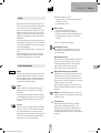
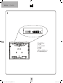
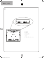
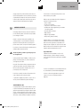
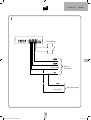
POWERBOX • POWER BOX • POWERBOX • POWERBOX
FUNK-INNENSTATION • WIRELESS INDOOR STATION • STATION INTÉRIEURE SANS FIL • DRAADLOOS BINNENSTATION
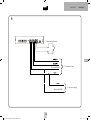
ANSCHLUSS-DIAGRAMM • CONNECTION DIAGRAM • SCHÉMA DE RACCORDEMENT • AANSLUITSCHEMA
VDV-507_I-Manual_210x240_Fin6.indd 2 21.01.16 11:43

DE
DEUTSCH | VDV-507
3
15
1B
2A 2B
14
1
VDV-507_I-Manual_210x240_Fin6.indd 3 21.01.16 11:43

VDV-507 | DEUTSCH
DE
4
3
POWERBOX • POWER BOX • POWERBOX • POWERBOX
FUNK-INNENSTATION • WIRELESS INDOOR STATION • STATION INTÉRIEURE SANS FIL • DRAADLOOS BINNENSTATION
ANSCHLUSS-DIAGRAMM • CONNECTION DIAGRAM • SCHÉMA DE RACCORDEMENT • AANSLUITSCHEMA
VDV-507_I-Manual_210x240_Fin6.indd 4 21.01.16 11:43

DE
DEUTSCH | VDV-507
5
4
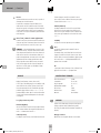
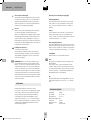
Externer Klingeltaster
VDV-507_I-Manual_210x240_Fin6.indd 5 21.01.16 11:43

VDV-507 | DEUTSCH
DE
6
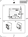
5. Richten Sie die beigefügte Bohrschablone mit einer Wasserwaage
gerade an der Stelle der Wand aus, an der die Inneneinheit
montiert werden soll. Alternativ können Sie auch das rückseitige
Gehäuse der Innenstation zum Markieren der
Bohrlöcher verwenden.
6. Fixieren Sie die Bohrschablone mit Klebeband und bohren Sie die
vier markierten Löcher (Ø 6 mm).
7. Entfernen Sie die Bohrschablone und stecken Sie in jedes Loch
einen der mitgelieferten Dübel.
8. Führen Sie die Anschlussleitung durch das Loch im Gehäuseboden
der Inneneinheit und verschrauben Sie das Gehäuse mit vier
Schrauben an der Wand.
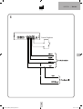
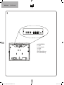
9. Schließen Sie die Leitungen an wie im Anschlussplan
(Abb. 4) gezeigt.
HINWEIS: Die Leitungen nicht zu kurz abschneiden. Im Gehäuseboden
befinden sich Laschen, dort kann die Leitung aufgewickelt werden.
10. Setzen Sie das Frontcover mit Monitor auf. Achten Sie darauf, dass
die Halteclips sicher einrasten.
HINWEIS: Achten Sie außerdem darauf, dass ein eventuell vorhan-
dener blanker Draht für die Abschirmung die Platine nicht berührt,
diesen am besten soweit wie möglich kürzen.
11. Verschrauben Sie das Frontcover wieder mit den
zwei Schrauben (16).
INBETRIEBNAHME
Anschluss Stromversorgung
Die Stromversorgung kann wahlweise an der Innen- oder Außenstation
angeschlossen werden.
Es ist auch möglich, die Stromversorgung an einem Sternpunkt
einzuspeisen, z.B. wenn alle Signalleitungen vom Sicherungskasten her
zu den Außen- und Inneneinheiten gelegt wurden. Das Netzteil ist dann
parallel mit Masse/GND und +15V zu verbinden.
Nachdem alle Komponenten montiert und angeschlossen sind, schalten
Sie die Betriebsspannung ein. Je nach Montageart stecken Sie dazu
das Steckernetzteil in eine geeignete Steckdose oder schalten den
Sicherungsautomat, an den das Hutschienennetzteil angeschlossen
ist, ein. Um die Anlage zu initialisieren, muss an der Außeneinheit
einmal geklingelt werden (bei mehreren Außenstationen muss an jeder
Außeneinheit einmal geklingelt werden).
HINWEIS: Vor allen Arbeiten an der Anlage schalten Sie die Betriebs-
spannung wieder aus!
Innenstation VDV-507 für Video-Türsprechanlage
Vielen Dank für den Kauf dieser Video-Innenstation. Diese kann
mit allen Komponenten aus den Systemen VISTADOOR und VISTUS
kombiniert werden. Wenn an der angeschlossenen Außenstation
geklingelt wird, spielt die Innenstation die eingestellte Klingelmelodie
ab und der Besucher ist auf dem Monitor zu sehen. Es kann dann mit
dem Besucher gesprochen und auch die Tür geöffnet werden (sofern ein
Türöffner angeschlossen ist).
LIEFERUMFANG
Innenstation mit 17,8 cm (7“) Bildschirmdiagonale
Befestigungsmaterial
Betriebs- und Montageanleitung
Bohrschablone
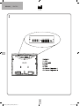
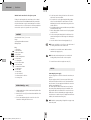
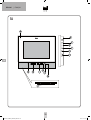
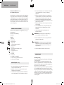
Legende
1 = Mikrofon
2 = Monitor-Taste
3 = Türöffner-Taste
4 = Sprech-Taste
5 = LED für Stummschaltung
6 = Ruhe-Taste
7 = Betriebs-LED
8 = Gesprächslautstärke-Einsteller
9 = Melodie-Taste
10 = Alarm-/ Interkom-Taste
11 = Minus-Taste
12 = Plus-Taste
13 = Menü-Taste
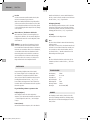
14 = Steckplatz für VTX-Bell
15 = Lautstärke-Einsteller für Klingelton
16 = Gehäuseschrauben
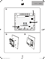
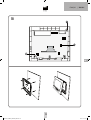
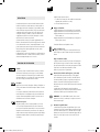
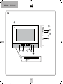
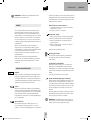
INSTALLATION (Abb. 2a+b)
1. Suchen Sie sich eine geeignete Stelle zur Montage der Inneneinheit
und verlegen Sie die Leitungen bis dorthin.
2. Entfernen Sie die beiden Schrauben (16) an der Inneneinheit und
heben Sie das Frontcover der Inneneinheit ab.
3. Mittig an den Seiten der Inneneinheit befinden sich zwei Halteclips.
Ziehen Sie das Frontcover vorsichtig ab.
4. Für die Einführung der Leitungen in das Gehäuse befindet sich
oben unter den Anschlussklemmen ein Loch im Gehäuse.
VDV-507_I-Manual_210x240_Fin6.indd 6 21.01.16 11:43

DE
DEUTSCH | VDV-507
7
Der Türöffner kann aktiviert werden, wenn
1. geklingelt wurde (ohne vorher ein Gespräch aufbauen zu müssen,
innerhalb von 60 Sekunden).
2. die Gegensprechfunktion aktiv ist.
Melodie einstellen
1. Sprech-Taste kurz drücken (Monitor schaltet ein).
2. Melodie-Taste kurz drücken, Melodie wird abgespielt.
3. Melodie-Taste kurz drücken, nächste Melodie wird abgespielt usw.
4. Sprech-Taste kurz drücken, um Melodie zu speichern (Monitor
schaltet aus).
Es stehen 16 verschiedene Melodien zur Auswahl.
Sprach-Lautstärke einstellen
Mit dem Einsteller für die Sprachlautstärke (8) an der Seite der
Inneneinheit können Sie die Lautstärke, mit der Sie den Besucher
hören, stufenlos einstellen.
Klingel-Lautstärke einstellen
Mit dem Einsteller (15) für die Klingel-Lautstärke auf der Hauptplatine
kann auch diese stufenlos eingestellt werden. Mit einem kleinen
Schraubendreher im Uhrzeigersinn drehen, erhöht die Lautstärke.
Gegen den Uhrzeigersinn drehen verringert die Lautstärke.
Achten Sie darauf, das Potentiometer nicht zu überdrehen.
Klingelmelodie deaktivieren (z.B. bei Nachtruhe)
Die Klingelmelodie kann deaktiviert werden. Dazu drücken Sie einmal
kurz auf die Ruhe-Taste (6) der Inneneinheit. Die LED (5) blinkt zur
Erinnerung bei deaktivierter Melodie rot. Um die Melodie wieder zu
aktivieren, drücken Sie erneut kurz auf die Ruhe-Taste. Die LED hört auf
zu blinken und die Melodie ist wieder aktiviert.
Das optische Signal (Leuchtrahmen der Sprech- und Türöffner-Taste)
bleibt auch bei deaktivierter Klingelmelodie aktiv und zeigt weiterhin
ein Klingeln an.
HINWEIS: Falls das VTX-BELL-Modul genutzt wird, so wird auch dieses
im Ruhemodus deaktiviert, d.h. die angeschlossenen Empfänger geben
ebenfalls kein Signal ab.
Alarmton aktivieren
Die Außenstation kann einen Alarmton abgeben (z.B. bei Belä-
stigungen). Dazu muss die Alarm-/ Interkom-Taste(10) an der
Inneneinheit gedrückt und gehalten werden. Der Alarmton wird nur
wiedergegeben, wenn die Taste innerhalb von 60 Sekunden nach
dem Klingeln gedrückt gehalten wird oder wenn die Sprechverbindung
aufgebaut ist.
BETRIEB
Klingeln an der Außeneinheit löst die Klingelmelodie an der Innenein-
heit aus, und der Besucher wird auf dem Monitor angezeigt. Betätigen
Sie die Sprech-Taste (4), um die Sprechverbindung herzustellen.
Nachdem Sie mit dem Besucher gesprochen haben, können Sie durch
Betätigen der Türöffner-Taste (3) die Tür öffnen (wenn ein Türöffner
angeschlossen ist) oder durch erneutes Betätigen der Sprech-Taste das
Gespräch beenden. Dadurch befindet sich die Innenstation wieder im
Standby-Betrieb.
Sind mehrere Außenstationen und/oder Zusatzkameras angeschlossen,
kann durch Betätigen der Monitor-Taste (2) zu den anderen Außenstati-
onen/Zusatzkameras umgeschaltet werden. Dies ist jederzeit möglich,
auch wenn nicht geklingelt wurde.
Solange das Bild einer Zusatzkamera aktiv ist, ist kein Sprechverkehr
möglich.
Durch zweimaliges Betätigen der Sprech-Taste wird die Innenstation
wieder in den Standbybetrieb geschaltet. Wird keine Taste gedrückt,
schaltet der Monitor automatisch nach ca. 60 Sekunden ab.
FUNKTIONEN DER ANLAGE
Klingeln
Wird die Klingel-Taste an der Außenstation gedrückt, gibt die Innenein-
heit Ihren eingestellten Klingelton wieder, und für ca. 60 Sekunden
blinken die Leuchtrahmen der Sprech- und der Türöffner-Taste an der
Inneneinheit. Des Weiteren aktiviert sich der Monitor während dieser
Zeit und das Bild der Außenkamera ist sichtbar.
Sprechen
Drücken Sie einmal auf die Sprech-Taste. Während die Sprechver-
bindung aktiv ist, leuchtet der Leuchtrahmen um die Sprech-Taste
dauerhaft blau.
Um das Gespräch zu beenden, betätigen die Sprech-Taste erneut. Die
Sprechverbindung kann jederzeit hergestellt werden. Es ist nicht nötig,
dass vorher geklingelt wird. Dazu betätigen Sie einfach einmal die
Sprech-Taste.
Tür öffnen
Ein angeschlossener Türöffner wird durch kurzes Drücken der Türöffner-
Taste für ca. 6 Sekunden oder 1 Sekunde aktiviert (siehe Anleitung
für die verwendete Außenstation), die Türöffner-Taste muss nicht
gedrückt gehalten werden. Zur Bestätigung wird ein doppelter Beep-Ton
an Außen- und Inneneinheit abgegeben und zusätzlich leuchtet das
Namensschild „grün“, solange der Türöffner aktiviert ist.
VDV-507_I-Manual_210x240_Fin6.indd 7 21.01.16 11:43

VDV-507 | DEUTSCH
DE
8
Interkom
Sind mehrere Innenstationen parallel miteinander verbunden, kann
zwischen diesen Innenstationen gesprochen werden.
Drücken Sie im Standby auf die Alarm-Taste, klingeln alle parallel an-
geschlossenen Innenstationen (alle Innenstationen einer Partei). Wird
an einer der klingelnden Innenstationen auf die Sprech-Taste gedrückt,
ist die Sprechverbindung aktiv. Um das Gespräch zu beenden, betätigen
Sie die Sprech-Taste.
Monitor aktivieren / Zusatzkameras durchschalten
Mit der Monitor-Taste (2) haben Sie jederzeit die Möglichkeit, den
Eingangsbereich zu überwachen, ohne dass jemand den Klingel-Taster
betätigt hat. Wird die Monitor-Taste ein zweites Mal gedrückt, schaltet
sich der Monitor ab.
HINWEIS: Bei einer angeschlossenen Zusatzkamera (oder mehren
Außenstationen) kann diese mit der Monitor-Taste aktiviert werden.
Beim ersten Drücken auf die Monitor-Taste aktiviert sich die Kamera der
Außenstation, ein zweites Drücken schaltet auf die erste Zusatzkamera,
ein drittes Drücken schaltet auf die zweite Zusatzkamera. Sind alle
Kameras durchgeschaltet, ist wieder das Bild der ersten Kamera zu
sehen. Ausschalten können Sie den Monitor nur durch zweimaliges
Drücken der Sprech-Taste oder Sie warten ca. 60 Sekunden, bis die
Anlage automatisch wieder in den Standby-Betrieb wechselt.
EINSTELLUNGEN
Monitoreinstellungen (Helligkeit, Kontrast, Farbe und Modus)
Der 7“-Monitor verfügt über ein On Screen Display (OSD), welches
über die Menü-Taste (13) aufgerufen wird, während der Monitor
aktiv ist. Jeder weitere Druck auf die Menü-Taste markiert die nächste
Einstellmöglichkeit im OSD. Mit den Tasten „+“ und „-“ (11+12)
können die Werte jeweils angepasst werden. Nach 5 Sekunden ohne
Tastendruck schaltet sich das OSD automatisch ab und die eingestellten
Werte werden gespeichert.
Folgende Einstellungen können vorgenommen werden:
Helligkeit (Brightness)
Um die Helligkeit des Monitors den örtlichen Gegebenheiten
anzupassen, rufen Sie das Menü über die Menü-Taste auf. Mit der Taste
„+“ wird die Helligkeit erhöht, mit der Taste „-“ wird die Helligkeit
verringert.
Kontrast (Contrast)
Um den Kontrast des Monitors anzupassen, rufen Sie das OSD mit der
Menü-Taste auf und drücken Sie ein weiteres Mal auf die Menü-Taste.
Der Punkt „Contrast“ im OSD sollte jetzt markiert sein und der Kontrast
kann über die Tasten „+“ und „-“ eingestellt werden.
Farbsättigung (Saturation)
Um die Farbsättigung des Monitors anzupassen, rufen Sie das OSD mit
der Menü-Taste auf und drücken Sie zwei weitere Male auf die Menü-
Taste. Der Punkt „Saturation“ im OSD sollte jetzt markiert sein und die
Farbsättigung kann über die Tasten „+“ und „-“ eingestellt werden.
Ton (Audio)
Dieser Menüpunkt ist für diese Anlage irrelevant.
Reset
Über diesen Punkt im OSD kann der Monitor auf die Werkseinstellung
zurückgesetzt werden.
Um den Monitor zu resetten, rufen Sie das OSD mit der Menü-Taste auf
und drücken Sie 5 weitere Male auf die Menü-Taste. Der Punkt „Reset“
sollte jetzt markiert sein. Um den Reset durchzuführen, drücken Sie
jetzt einmal auf die Taste „+“. Das OSD verschwindet sofort und die
Werkseinstellungen sind wieder hergestellt.
Exit
Über diesen Punkt kann das OSD verlassen werden. Wenn „Exit“ im
OSD markiert ist, drücken Sie einmal auf die Taste „+“, um das OSD
zu verlassen.
TECHNISCHE DATEN
Betriebsspannung: 15Volt DC
Stromaufnahme: 270 ± 50mA
Temperaturbereich: 0-50°C
Max. Luftfeuchtigkeit: 85%
Bildschirmdiagonale: 178mm
Auflösung des Monitors: 1024x600
Abmessungen: 220x160x28mm (BXHXT)
HINWEISE
Unter Einwirkung von starken statischen, elektrischen oder hochfre-
quenten Feldern (Entladungen, Mobiltelefonen, Funkanlagen, Handys,
Mikrowellen) kann es zu Funktionsbeeinträchtigungen der Geräte (des
Gerätes) kommen.
VDV-507_I-Manual_210x240_Fin6.indd 8 21.01.16 11:43

DE
DEUTSCH | VDV-507
9
tie werden auf die Reparatur oder den Wiedereinbau irgendeines Teils
des Gerätes begrenzt und gelten nur unter der Bedingung, dass keine
unbefugten Veränderungen oder versuchte Reparaturen vorgenommen
wurden. Ihre gesetzlichen Rechte als Kunde werden in keiner Weise
durch diese Garantie beeinträchtigt.
Bitte beachten Sie!
Es besteht kein Anspruch auf Garantie in u. a. folgenden Fällen:
• Bedienungsfehler
• leere Batterien oder defekte Akkus
• falsche Codierung/Kanalwahl
• Störungen durch andere Funkanlagen (z.B. Handybetrieb)
• Fremdeingriffe/-wirkungen
• Mechanische Beschädigungen
• Feuchtigkeitsschäden
• Kein Garantie-Nachweis (Kaufbeleg)
Bei Schäden, die durch Nichtbeachten dieser Bedienungsanleitung
verursacht werden, erlischt der Garantieanspruch. Für Folgeschäden
übernehmen wir keine Haftung! Bei Sach- oder Personenschäden, die
durch unsachgemäße Handhabung oder Nichtbeachten der Sicherheits-
hinweise verursacht werden, übernehmen wir keine Haftung. In solchen
Fällen erlischt jeder Garantieanspruch!
Haftungsbeschränkung:
Der Hersteller ist nicht für den Verlust oder die Beschädigung irgendwel-
cher Art einschließlich der beiläufigen oder Folgeschäden haftbar, die
direkt oder indirekt aus der Störung dieses Produktes resultieren.
Diese Bedienungsanleitung ist eine Publikation der
m-e GmbH modern-electronics,
An den Kolonaten 37, 26160 Bad Zwischenahn
Diese Bedienungsanleitung entspricht dem technischen Stand bei
Drucklegung. Änderung in Technik und Ausstattung vorbehalten.
Reinigung und Pflege
Netzbetriebene Geräte vor dem Reinigen vom Netz trennen (Stecker
ziehen). Die Oberfläche des Gehäuses kann mit einem mit Seifenlauge
angefeuchtetem weichen Tuch gereinigt werden. Verwenden Sie keine
Scheuermittel oder Chemikalien. Staubablagerungen an Lüftungs-
schlitzen nur mit einem Pinsel lösen und gegebenenfalls mit einem
Staubsauger absaugen. Die Saugdüse nicht direkt an das Gerät halten.
SICHERHEITSHINWEISE
Bei Schäden, die durch Nichtbeachten dieser Bedienungsanleitung
verursacht werden, erlischt der Garantieanspruch. Für Folgeschäden
übernehmen wir keine Haftung!
Bei Sach- oder Personenschäden, die durch unsachgemäße Handha-
bung oder Nichtbeachten der Sicherheitshinweise verursacht werden,
übernehmen wir keine Haftung. In solchen Fällen erlischt jeder
Garantieanspruch!
Aus Sicherheits- und Zulassungsgründen (CE) ist das eigenmächtige
Umbauen und/oder Verändern des Produkts nicht gestattet.
Zerlegen Sie das Produkt nicht! Es besteht die Gefahr eines
lebensgefährlichen elektrischen Schlages!
Lassen Sie das Verpackungsmaterial nicht achtlos liegen, Plastikfolien/-
tüten, Styroporteile etc. könnten für Kinder zu einem gefährlichen
Spielzeug werden.
Das Gerät ist nur für trockene Innenräume geeignet (keine Badezimmer
o.ä. Feuchträume). Vermeiden Sie das Feucht- oder Nasswerden des
Geräts. Es besteht die Gefahr eines lebensgefährlichen elektrischen
Schlages!
Wenden Sie sich an eine Fachkraft, wenn Sie Zweifel über die Arbeitswei-
se, die Sicherheit oder den Anschluss des Geräts haben.
Gehen Sie vorsichtig mit dem Produkt um - durch Stöße, Schläge oder
dem Fall aus bereits geringer Höhe wird es beschädigt.
2 JAHRE BESCHRÄNKTE GARANTIE
Es wird für die Dauer von 2 Jahren ab Kaufdatum gewährleistet, dass
dieses Produkt frei von Defekten in den Materialien und in der Ausfüh-
rung ist. Dies trifft nur zu, wenn das Gerät in üblicher Weise benutzt wird
und regelmäßig instand gehalten wird. Die Verpflichtungen dieser Garan-
VDV-507_I-Manual_210x240_Fin6.indd 9 21.01.16 11:43

GB
VDV-507 | ENGLISH
1010
1A
VDV-507_I-Manual_210x240_Fin6.indd 10 21.01.16 11:43

GB
ENGLISH | VDV-507
11
15
1B
14
1
2A 2B
VDV-507_I-Manual_210x240_Fin6.indd 11 21.01.16 11:43

GB
VDV-507 | ENGLISH
1212
3
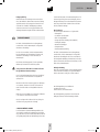
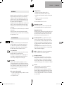
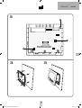
CONNECTIONS
1= +15V
2= Ground/GND
3= Audio
4= Video
40= External bell push +
41= External bell push -
VDV-507_I-Manual_210x240_Fin6.indd 12 21.01.16 11:43

GB
ENGLISH | VDV-507
13
4
External bell push
Ground/GND
To power supply
To external unit
Ground/GND
VDV-507_I-Manual_210x240_Fin6.indd 13 21.01.16 11:43

GB
VDV-507 | ENGLISH
1414
VDV-507 indoor unit for video door phone system
Thank you for purchasing this video internal unit. It can be combined
with all components from the VISTADOOR and VISTUS systems. When
the linked external unit is rung, the internal unit plays the set bell tone
and the visitor can be seen on the monitor. You can then speak with the
visitor and also open the door (provided a door opener is linked).
CONTENTS
Internal unit with 17.8 cm (7”) screen size
Fixings
Operating and installation instructions
Drilling template
Key
1 = Microphone
2 = Monitor button
3 = Door opener button
4 = Voice button
5 = LED for muting function
6 = Sleep button
7 = Operating LED
8 = Voice volume adjuster
9 = Bell tone button
10 = Alarm/intercom button
11 = Minus button
12 = Plus button
13 = Menu button
14 = Slot for VTX bell
15 = Volume adjuster for bell tone
16 = Housing screws
INSTALLATION (Fig. 2a+b)
1. Identify a suitable place to fit the internal unit and lay all the cables
needed to this point.
2. Remove the two screws (16) from the internal unit and lift the front
cover off the unit.
3. There are two attachment clips at the centre of the sides of the
internal unit. Carefully pull off the front cover.
4. For cable entry into the housing, the latter has a hole in it at the
top below the connection terminals.
5. Use a spirit level to correctly align the supplied drilling template
at the point on the wall where the internal unit is to be fitted.
Alternatively, the back of the internal unit housing can be used to
mark the drill holes.
6. Fix the drilling template in position with adhesive tape and drill the
four marked holes (Ø 6 mm).
7. Take the drilling template off and insert one of the plugs supplied
in each of the holes.
8. Feed the connecting cable through the hole in the bottom of the
internal unit housing and screw the housing to the wall using the
four screws.
9. Connect the cables as shown in the wiring diagram (Fig. 4).
NOTE: Do not cut the cables too short. There are clips in the bottom of
the housing that the cable can be wound around.
10. Attach the front cover with the monitor. Make sure that the
attachment clips engage properly.
NOTE: Also make sure that any bare wires do not touch the PCB
shielding; ideally the wires should be as short as possible.
11. Screw the front cover back on using the two screws (16).
STARTUP
Connecting the power supply
The power supply can be connected to the internal or external unit, as
preferred.
The power supply can also be fed in at a star point, if all the signal
cables have been laid from the fuse box to the external and internal
units, for instance. The power supply unit should then be connected in
parallel to ground/GND and +15 V.
Once all the components have been fitted and connected, switch on
the operating voltage. Depending on the type of installation, either
plug the mains adapter into a suitable socket or switch on the circuit
breaker that is connected to the DIN rail power supply unit. Ring the
external unit once to initialise the system (if multiple external units are
installed, each external unit must be rung once).
NOTE: Switch the operating voltage off again before carrying out any
work on the system!
VDV-507_I-Manual_210x240_Fin6.indd 14 21.01.16 11:43

GB
ENGLISH | VDV-507
15
OPERATION
Ringing the external unit sounds the bell tone on the internal unit, and
the visitor is displayed on the monitor. Press the voice button (4) to
establish voice communication. Having spoken to the visitor, you can
open the door (if a door opener is linked) by pressing the door opener
button (3) or end the conversation by pressing the voice button again.
This returns the internal unit to standby mode.
If multiple external units and/or additional cameras are linked, you can
switch to the other external units/additional cameras by pressing the
monitor button (2). This can be done at any time, even if the bell has
not been rung.
Voice communication is not possible while the image from an additional
camera is active.
Pressing the voice button twice returns the internal unit to standby
mode. If a button is not pressed, the monitor switches off automatically
after approximately 60 seconds.
SYSTEM FUNCTIONS
Ringing
If the bell push on the external unit is pressed, the internal unit emits
the bell tone that has been set, and the luminous surrounds of the
voice button and door opener button on the internal unit flash for
approximately 60 seconds. The monitor is also activated during this
time and the image from the external camera can be seen.
Voice communication
Press the voice button once. The luminous surround of the voice button
lights up blue while voice communication is active.
To terminate voice communication, press the voice button again. You
can re-establish voice communication at any time. The bell does not
need to be rung first. Simply press the voice button again.
Door opening
A linked door opener is activated for approximately 6 seconds or 1
second by briefly pressing the door opener button (see instructions for
the external unit used). You do not have to hold the door opener button
down. Confirmation is provided by a double beep sound at the external
and internal unit, and the name tag lights up green for the time the
door opener is activated.
The door opener can be activated if:
1. The bell has been rung (without having to establish voice communi-
cation first, within 60 seconds).
2. The reply function is active.
Setting the bell tone
1. Briefly press the voice button (monitor switches on).
2. Briefly press the bell tone button, the bell tone is played.
3. Briefly press the bell tone button, the next bell tone is played, and
so on.
4. Briefly press the voice button to save the bell tone
(monitor switches off).
There are 16 different bell tones to choose from.
Adjusting the voice volume
The voice volume adjuster (8) on the side of the internal unit allows
you to freely adjust the volume of voice reception from the visitor.
Adjusting the bell volume
The adjuster (15) for the bell volume on the main PCB can also be used
to freely adjust the volume. Increase the volume by turning clockwise
with a small screwdriver. Turn anti-clockwise to decrease the volume.
Make sure that you do not turn the potentiometer too far.
Deactivating the bell tone (e.g. if night-time quiet is required)
The bell tone can be deactivated. To do this, press the sleep button
(6) of the internal unit once briefly. The LED (5) flashes red to remind
you that the tone is deactivated. To reactivate the bell tone, press the
sleep button briefly again. The LED will stop flashing and the bell tone
is reactivated.
The optical signal (luminous surrounds of the voice and door opener
button) remains active even when the bell tone is deactivated and will
continue to indicate the bell being rung.
NOTE: If the VTX BELL module is used, it is also deactivated in sleep
mode, i.e. the linked receivers do not emit a signal either.
Activating the alarm tone
The external unit can emit an alarm tone (e.g. where someone is
making a nuisance of themselves). To do this, press and hold down
the alarm/intercom button (10) on the internal unit. The alarm tone
will only be emitted if the button is pressed and held down within 60
seconds of the bell being rung, or if voice communication is established.
Intercom
If multiple internal units are connected together in parallel, these
internal units can communicate with one another.
When the alarm button is pressed in standby mode, all the internal
units that are linked in parallel ring (all internal units of the same par-
ty). Voice communication is activated when the voice button is pressed
on one of the ringing internal units. To terminate voice communication,
press the voice button.
VDV-507_I-Manual_210x240_Fin6.indd 15 21.01.16 11:43

GB
VDV-507 | ENGLISH
16
INNENSTATION
INDOOR STATION
BOÎTIER INTÉRIEUR
BINNENSTATION
Activating monitor / switching between additional cameras
Using the monitor button (2), you can monitor the entrance area at any
time without waiting for someone to press the bell push. Pressing the
monitor button a second time switches off the monitor.
NOTE: If an additional camera is connected (or multiple external units),
it can also be activated using the monitor button. Pressing the monitor
button once activates the camera of the external unit, pressing it a
second time switches to the first additional camera, and pressing it a
third time switches to the second additional camera. Once you flipped
through all the cameras the image from the first camera is shown again.
The monitor can only be switched off by pressing the voice button twice
or waiting approximately 60 seconds for the system to automatically
return to standby mode.
SETTINGS
Monitor settings (brightness, contrast, colour and mode)
The 7“ monitor has an On Screen Display (OSD), which can be called
via the menu button (13) when the monitor is active. Each press of the
menu button highlights the next option in the OSD. The „+“ and „-“
buttons (11 + 12) can be used to adjust the relevant values. If a button
has not been pressed for 5 seconds, the OSD switches off automatically
and the set values are saved.
The following settings can be made:
Brightness
To adjust the brightness of the monitor to the local conditions, call
the menu via the menu button. Use the „+“ button to increase the
brightness and the „-“ button to decrease the brightness.
Contrast
To adjust the contrast of the monitor, call the OSD with the menu button
and press the menu button again. The „Contrast“ item should now be
highlighted in the OSD and the contrast can be set via the „+“ and „-“
buttons.
Saturation
To adjust the saturation of the monitor, call the OSD with the menu
button and press the menu button again twice. The „Saturation“ item
should now be highlighted in the OSD and the saturation can be set via
the „+“ and „-“ buttons.
Audio
This menu item is not relevant for this system.
Reset
This item in the OSD can be used to reset the monitor to the factory
settings.
To reset the monitor, call the OSD with the menu button and press
the menu button again five times. The „Reset“ item should now be
highlighted. Press the „+“ button once to perform a reset. The OSD
immediately disappears and the factory settings are restored.
Exit
The OSD can be exited via this item. When „Exit“ is highlighted in the
OSD, press the „+“ button once to exit the OSD.
TECHNICAL DATA
Operating voltage: 15 V DC
Power consumption: 270 ± 50 mA
Temperature range: 0 to +50°C
Maximum air humidity: 85%
Screen size: 178mm (7’’)
Monitor resolution: 1024x600
Dimensions: 220 x 160 x 28 mm (wxhxd)
NOTES
The functionality of the unit can be affected by the influence of strong
static, electrical or high frequency fields (discharging, mobile phones,
radios, microwaves).
Cleaning and maintenance
Always disconnect mains powered units from the mains supply before
cleaning (disconnect the plug). The unit housing can be cleaned using
a soapy soft cloth. Do not use any abrasive materials or chemicals.
Remove dust build-up from ventilation slits using a brush and clean up
using a vacuum cleaner. Do not hold the vacuum cleaner nozzle directly
against the unit.
SAFETY NOTES
The warranty will be null and void in case of damages arising from
violations of these operating instructions. We are not liable for
consequential damages!
VDV-507_I-Manual_210x240_Fin6.indd 16 21.01.16 11:43

GB
ENGLISH | VDV-507
17
We accept no liability for material damages or injuries arising from
inappropriate use or violation of the safety instructions. In such cases
all warranty claims are null and void!
For reasons of safety and licensing (CE), unauthorised conversion and /
or modification of the product is prohibited.
Do not take the product apart! There is a danger of lethal
electric shock!
Do not leave packaging material lying about since plastic foils and
pockets and polystyrene parts etc. could be lethal toys for children.
The device is suitable only for dry interior rooms (not bathrooms and
other moist places). Do not allow the device to get moist or wet. There
is a danger of lethal electric shock!
In industrial institutions, the accident prevention regulations of the
Association of Commercial Professional Associations for electrical instal-
lations and equipment must be observed. Please consult a specialist
should you have doubts regarding the method of operation, the safety,
or the connections of the device.
Handle the product with care – it is sensitive to bumps, knocks or falls
even from low heights.
2 YEAR LIMITED GUARANTEE
For two years after the date of purchase, the defect-free condition of
the product model and its materials is guaranteed. This guarantee is
only valid when the device is used as intended and is subject to regular
maintenance checks. The scope of this guarantee is limited to the
repair or reinstallation of any part of the device, and is only valid if no
unauthorised modifications or attempted repairs have been undertaken.
Customer statutory rights are not affected by this guarantee.
Please note!
No claim can be made under guarantee in the following circumstances:
• Operational malfunction
• Empty batteries or faulty accumulator
• Erroneous coding/channel selection
• Fault through other radio installation (i.e. mobile operation)
• Unauthorised modifications / actions
• Mechanical damage
• Moisture damage
• No proof of guarantee (purchase receipt)
Claims under warranty will be invalidated in the event of damage
caused by non-compliance with the operating instructions. We do not
accept any responsibility for consequential damage! No liability will be
accepted for material damage or personal injury caused by inappropri-
ate operation or failure to observe the safety instructions. In such cases,
the guarantee will be rendered void.
Liability limitation
The manufacturer is not liable for loss or damage of any kind including
incidental or consequential damage which is the direct or indirect result
of a fault to this product.
These operating instruction are published by
m-e GmbH modern-electronics,
An den Kolonaten 37, 26160 Bad Zwischenahn/Germany
The operating instructions reflect the current technical specifications at
time of print. We reserve the right to change the technical or physical
specifications.
VDV-507_I-Manual_210x240_Fin6.indd 17 21.01.16 11:43

FR
VDV-507 | FRANÇAIS
18
1A
VDV-507_I-Manual_210x240_Fin6.indd 18 21.01.16 11:43

FR
FRANÇAIS | VDV-507
19
15
1B
14
1
VDV-507_I-Manual_210x240_Fin6.indd 19 21.01.16 11:43

FR
VDV-507 | FRANÇAIS
20
3
RACCORDS
1= +15V
2= Masse/GND
3= Audio
4= Video
40= Bouton de sonnette externe +
41= Bouton de sonnette externe -
VDV-507_I-Manual_210x240_Fin6.indd 20 21.01.16 11:43
La page est en cours de chargement...
La page est en cours de chargement...
La page est en cours de chargement...
La page est en cours de chargement...
La page est en cours de chargement...
La page est en cours de chargement...
La page est en cours de chargement...
La page est en cours de chargement...
La page est en cours de chargement...
La page est en cours de chargement...
La page est en cours de chargement...
La page est en cours de chargement...
La page est en cours de chargement...
La page est en cours de chargement...
La page est en cours de chargement...
La page est en cours de chargement...
-
 1
1
-
 2
2
-
 3
3
-
 4
4
-
 5
5
-
 6
6
-
 7
7
-
 8
8
-
 9
9
-
 10
10
-
 11
11
-
 12
12
-
 13
13
-
 14
14
-
 15
15
-
 16
16
-
 17
17
-
 18
18
-
 19
19
-
 20
20
-
 21
21
-
 22
22
-
 23
23
-
 24
24
-
 25
25
-
 26
26
-
 27
27
-
 28
28
-
 29
29
-
 30
30
-
 31
31
-
 32
32
-
 33
33
-
 34
34
-
 35
35
-
 36
36


dans d''autres langues
- English: Me VDV-847-TW
- Deutsch: Me VDV-847-TW
- Nederlands: Me VDV-847-TW
Documents connexes
-
Me VDV-20208-S Mode d'emploi
-
-
-
-
-
-
-
Me VDV-625-WW Le manuel du propriétaire
-
-
m-e VDV-510.1 Mode d'emploi