
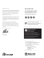
Need help? Visit Sauder.com to view video assembly tips or chat with a live rep.
Prefer the phone? Call 1-800-523-3987.
Share your journey!
sauder.com
Congratulations. You
are now an adult.
NOTE: THIS INSTRUCTION
BOOKLET CONTAINS IMPORTANT
SAFETY INFORMATION.
PLEASE READ AND KEEP FOR
FUTURE REFERENCE.
Enlish p 1-25
Français p 26-29
Español p 30-32
Lot # 397205 10/11/16
Purchased: __________________
Be sure to ive us a rin before
makin any returns. 1-800-523-3987
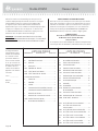
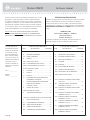
Lateral File
Shoal Creek Collection | Model 418658

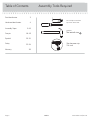
Table of Contents Assembly Tools Required
Part Identifi cation
Hardware Identifi cation
Assembly Steps
Français
Español
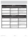
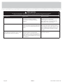
Safety
Warranty
Hammer
Not actual size
No. 2 Phillips Screwdriver
Tip Shown Actual Size
Skip the power trip.
This time.
3
4
5-25
26-29
30-32
33-34
35
418658 www.sauder.com/servicesPae 2

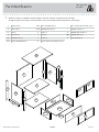
Part Identifi cation
å While not all parts are labeled, some of the parts will have a label or an inked letter on the ede
to help distinuish similar parts from each other. Use this part identifi cation to help identify similar parts.
Now you know
our ABCs.
A RIGHT END (1)
B LEFT END (1)
C2 TOP (1)
D BOTTOM (1)
D61 DRAWER BACK (1)
D87 RIGHT DRAWER SIDE (1)
D88 LEFT DRAWER SIDE (1)
D729 DRAWER BOTTOM (1)
E SHELF (1)
F BACK (1)
G DOOR (2)
H RIGHT FRONT/LEFT REAR LEG (2)
I LEFT FRONT/RIGHT REAR LEG (2)
J DRAWER FRONT (1)
K DRAWER BOX FRONT (1)
M63 DRAWER BRACE (1)
X END MOLDING (2)
A
B
C2
D
E
F
G
G
H
H
I
I
J
K
X
X
M63
D87
D88
D61
D729
418658www.sauder.com/services
Pae 3

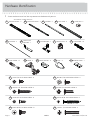
Hardware Identifi cation
å Screws are shown actual size. You may receive extra hardware with your unit.
(EXTENSION SET SHOWN SEPARATED)
EXTENSION RAIL - 2
L
EXTENSION SLIDE - 2
M
FILE ROD - 2
9B
FILE BAR - 2
1B
FILE GLIDE - 2
6B
BLACK 1-1/8" PAN HEAD SCREW - 4
9S
SILVER 3/4" MACHINE SCREW - 4
20S
SILVER 1-1/4" MACHINE SCREW - 4
35S
BROWN 7/16" LARGE HEAD SCREW - 4
6S3S
GOLD 5/16" FLAT HEAD SCREW - 8
SILVER 5/8" FLAT HEAD SCREW - 8
23S
PULL - 4
7K
10A
SLIDE CAM - 2
22H
HINGE SPACER - 4
BLACK 9/16" FLAT HEAD SCREW - 6
32S
CAM SCREW - 13
8F
HIDDEN CAM - 31
1F
CAM DOWEL - 18
2F
30S
BLACK 1-9/16" FLAT HEAD SCREW - 5
14H
HINGE - 4
FRONT FILE
BRACKET - 1
11B
29M
BUMPER CARD - 1
FILE BRACKET - 1
12B
418658 www.sauder.com/servicesPae 4

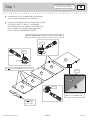
Step 1
Look for this icon. It means a
video assembly tip is available at
www.sauder.com/services/tips
å
Assemble your unit on a carpeted fl oor or on the empty
carton to avoid scratchin your unit or the fl oor.
å
Push thirty-one HIDDEN CAMS (1F) into the ENDS (A and B),
BOTTOM (D), SHELF (E), BACK (F), and DRAWER
BRACE (M63). Then, insert eihteen CAM DOWELS (2F)
into the HIDDEN CAMS except the lon edes of the
ENDS (A and B) and DRAWER BRACE (M63).
A
B
D
E
F
M63
Arrow
1F
2F
1F
2F
Arrow
(31 used)
(15 used)
Arrow
1F
2F
Do not tihten the HIDDEN CAMS in this step.
Do not insert CAM DOWELS into these edes.
Insert the metal end of the CAM
DOWEL into the HIDDEN CAM.
Arrow
Do not insert a
CAM DOWEL
into this ede.
418658www.sauder.com/services
Pae 5

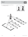
å
Turn thirteen CAM SCREWS (8F) into the LEGS (H and I)
and DRAWER BOX FRONT (K).
Step 2
8F
(13 used)
H
H
I
I
K
418658 www.sauder.com/servicesPae 6

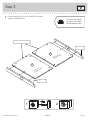
å
Fasten one of the LEGS (H and I) to the ENDS (A and B).
Tihten six HIDDEN CAMS.
Step 3
Anled ede
Anled ede
A
B
H
I
Surface with
HIDDEN CAMS
Surface with
HIDDEN CAMS
12
Just think. The sooner
you do this, the sooner
you do somethin else.
418658www.sauder.com/services
Pae 7
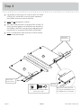
Ede with CAM DOWELS

å
Flip the ENDS (A and B) over. Turn six BLACK 9/16" FLAT HEAD
SCREWS (32S) into the ENDS (A and B) until the shoulders of
the SCREWS rest on the surfaces of the ENDS.
å
NOTE: Do not overtihten the SCREWS.
å
Now, slide the END MOLDINGS (P) onto the ENDS (A and B). To
do this, line up the rooves in the MOLDINGS over the heads of
the SCREWS in the ENDS. Usin your hands, apply pressure on
the MOLDINGS as you uide the MOLDINGS onto the ENDS.
å
NOTE: If the MOLDINGS come up o of the SCREWS, remove
them and slide them on aain.
Step 4
These edes
should be even.
These edes
should be even.
Shoulder
Apply pressure with your hands
as you uide the MOLDINGS over
the SCREWS and onto the ENDS.
BLACK 9/16" FLAT HEAD SCREW
(6 used in this step)
32S
A
B
P
P
418658 www.sauder.com/servicesPae 8

å
Flip the ENDS (A and B) over. Fasten the remainin LEGS (H
and I) to the ENDS (A and B). Tihten six HIDDEN CAMS.
Step 5
A
B
Surface with
HIDDEN CAMS
Surface with
HIDDEN CAMS
H
I
Anled ede
Anled ede
418658www.sauder.com/services
Pae 9

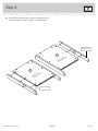
å
Separate the EXTENSION SLIDES (M) from the
EXTENSION RAILS (L) as shown in the upper diaram. Be
prepared, the parts are reasy.
å
Fasten the EXTENSION RAILS (L) to the ENDS (A and B).
Use four GOLD 5/16" FLAT HEAD SCREWS (3S).
å
NOTE: For each EXTENSION RAIL, turn a SCREW into the
hole shown in the enlared diaram.Then, slide the inner
cartride of the EXTENSION RAIL out to fi nd the other
hole that lines up with the hole in the END. Turn a SCREW
into this hole.
Step 6
Open end
Open end
GOLD 5/16" FLAT HEAD SCREW
(4 used in this step)
3S
Push the black lever in and pull the SLIDE from the RAIL.
Hole
L
L
L
M
418658 www.sauder.com/servicesPae 10
A
B

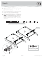
å
Fasten the SHELF (E) to the BACK (F). Tihten two
HIDDEN CAMS.
Step 7
Ede with CAM DOWELS
Finished ede
Surface with
HIDDEN CAMS
Surface with
HIDDEN CAMS
E
F
Start Tighten
Arrow
Minimum
190 derees
Caution
Risk of damae or
injury. HIDDEN CAMS
must be completely
tihtened. HIDDEN
CAMS that are not
completely tihtened
may loosen, and parts
may separate. To
completely tihten:
Arrow
Maximum
210 derees
418658www.sauder.com/services
Pae 11

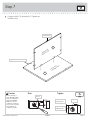
å
Fasten the BOTTOM (D) to the BACK (F). Tihten two
HIDDEN CAMS.
Step 8
Finished ede
Surface with
HIDDEN CAMS
F
Arrow
Minimum
190 derees
Maximum
210 derees
D
418658 www.sauder.com/servicesPae 12

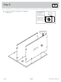
å
Fasten the ENDS (A and B) to the BOTTOM (D) and
SHELF (E). Tihten eiht HIDDEN CAMS.
Step 9
Arrow
Minimum
190 derees
Maximum
210 derees
A
B
D
E
Surface with
HIDDEN CAMS
418658www.sauder.com/services
Pae 13
Surface without HIDDEN CAMS

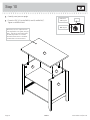
å
Carefully stand your unit upriht.
å
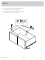
Fasten the TOP (C2) to the ENDS (A and B) and BACK (F).
Tihten six HIDDEN CAMS.
Step 10
Arrow
Minimum
190 derees
Maximum
210 derees
A
B
C2
F
418658 www.sauder.com/servicesPae 14
Meet Part (C2). This component has
been enineered to be lihter, stroner,
faster… well ok. Not technically faster.
But defi nitely makes for a sturdier
Lateral File that’s easier to assemble
and friendlier to the environment.

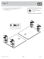
å
Fasten four HINGES (14H) and four HINGE SPACERS (22H)
to the DOORS (G). Use eiht SILVER 5/8" FLAT
HEAD SCREWS (23S).
Step 11
G
G
14H
14H
14H
14H
22H
22H
22H
22H
SILVER 5/8" FLAT HEAD SCREW
(8 used for the HINGES)
23S
Don't worry. It isn't
Rome. This can be built
in a day.
418658www.sauder.com/services
Pae 15

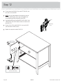
å
Fasten one of the DOORS (G) to the LEFT END (B). Use
the screws in the HINGES.
å
NOTE: You may need to loosen the mountin screw to
slide the HINGE slihtly out of the slot. Retihten the
screw before mountin the HINGE to the END.
å
Peel the BUMPER from the BUMPER CARD (29M). Stick
a BUMPER on the DOOR where it comes in contact with
the SHELF (E).
å
Fasten a PULL (7K) to the DOOR (G). Use two SILVER
3/4" MACHINE SCREWS (20S).
å
Repeat this step for the other DOOR (G).
Step 12
29M
SILVER 3/4" MACHINE SCREW
(4 used in this step)
20S
7K
(2 used)
B
E
G
418658 www.sauder.com/servicesPae 16
Mountin
screw
Stop
Hine

Step 13
Adjustin screw (horizontal)
Mountin screw (depth)
(vertical adjustment)
418658www.sauder.com/services
Pae 17
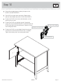
å
Refer to the enlared diaram to identify the parts on the
HINGES and HINGE BRACKETS.
å
The DOORS may need some adjustments. Follow the text
below to make needed adjustments. DOOR ADJUSTMENTS:
å
To adjust the DOORS from side to side (horizontal), turn the
adjustin screw in or out.
å
To adjust the DOORS up and down (vertical), loosen both
screws that fasten the HINGE BRACKETS to the END. Move the
DOORS up or down to the desired location. Tihten the screws
after makin adjustments.
å
To adjust the DOORS in or out (depth), loosen the mountin
screw one turn and move the DOORS in or out, as needed.
Tihten the mountin screw after makin adjustments.

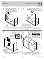
Step 14
å
Insert the DRAWER SIDES (D87 and D88) at an angle
into the slot at each end of the DRAWER BOX FRONT (K).
å
Slide the DRAWER BOTTOM (D729) into the grooves
in the DRAWER SIDES (D87 and D88) and DRAWER
BOX FRONT (K).
å
Fasten the DRAWER BRACE (M63) to the DRAWER
BOX FRONT (K). Tighten one HIDDEN CAM.
å
Fasten the DRAWER BACK (D61) to the DRAWER
SIDES (D87 and D88) and DRAWER BRACE (M63). Use
five BLACK 1-9/16" FLAT HEAD SCREWS (30S).
The tabs should insert freely into the
slots. Gently tilt the DRAWER SIDES side
to side until the tabs slip into the slots.
Surface with
HIDDEN CAM
12
3
4
Be sure the DRAWER
BOTTOM inserts into the
DRAWER FRONT roove.
With the palm of your hand, tap the
DRAWER BOTTOM down into the roove.
Groove
Arrow
Maximum
210 derees
Minimum
190 derees
K
K
D87
D87
D87
D88
D88
D88
D61
VIEW THE T-LOCK BOX VIDEO
D729
Be sure the
DRAWER
BOTTOM
inserts into
the DRAWER
BACK roove.
30S
Start each screw a few turns before
completely tihtenin any of them.
BLACK 1-9/16" FLAT HEAD SCREW
(5 used in this step)
M63
M63
K
418658 www.sauder.com/servicesPae 18

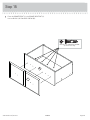
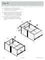
å
Fasten the DRAWER FRONT (J) to the DRAWER BOX FRONT (K).
Use four BLACK 1-1/8" PAN HEAD SCREWS (9S).
Step 15
K
BLACK 1-1/8" PAN HEAD SCREW
(4 used in this step)
9S
J
418658www.sauder.com/services
Pae 19

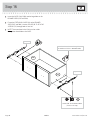
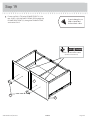
å
Insert the SLIDE CAMS (10A) into the lare holes in the
DRAWER SIDES (D87 and D88).
å
Fasten the EXTENSION SLIDES (M) to the DRAWER
SIDES (D87 and D88). Use four GOLD 5/16" FLAT HEAD
SCREWS (3S) throuh holes #1 and #4.
å
NOTE: The screw head in the CAM must be visible
throuh the slotted hole in the SLIDE.
Step 16
M
M
D87
D88
Open end
Open end
Screw head - turn CAM to line up holes in
the SLIDES with holes in DRAWER SIDES
GOLD 5/16" FLAT HEAD SCREW
(4 used in this step)
3S
1
1
2
2
3
3
4
4
10A
10A
418658 www.sauder.com/servicesPae 20
La page est en cours de chargement...
La page est en cours de chargement...
La page est en cours de chargement...
La page est en cours de chargement...
La page est en cours de chargement...
La page est en cours de chargement...
La page est en cours de chargement...
La page est en cours de chargement...
La page est en cours de chargement...
La page est en cours de chargement...
La page est en cours de chargement...
La page est en cours de chargement...
La page est en cours de chargement...
La page est en cours de chargement...
La page est en cours de chargement...
La page est en cours de chargement...
-
 1
1
-
 2
2
-
 3
3
-
 4
4
-
 5
5
-
 6
6
-
 7
7
-
 8
8
-
 9
9
-
 10
10
-
 11
11
-
 12
12
-
 13
13
-
 14
14
-
 15
15
-
 16
16
-
 17
17
-
 18
18
-
 19
19
-
 20
20
-
 21
21
-
 22
22
-
 23
23
-
 24
24
-
 25
25
-
 26
26
-
 27
27
-
 28
28
-
 29
29
-
 30
30
-
 31
31
-
 32
32
-
 33
33
-
 34
34
-
 35
35
-
 36
36


dans d''autres langues
Documents connexes
-
Sauder 420406 Mode d'emploi
-
-
-
-
-
-
-
-
-

