Sauder Heritage Hill Lateral File 102702 Manuel utilisateur
- Taper
- Manuel utilisateur

Need help? Visit Sauder.com to view video assembly tips or chat with a live rep.
Prefer the phone? Call 1-800-523-3987.
Share your journey!
sauder.com
NOTE: THIS INSTRUCTION
BOOKLET CONTAINS IMPORTANT
SAFETY INFORMATION.
PLEASE READ AND KEEP FOR
FUTURE REFERENCE.
Enlish p 1-22
Français p 23-25
Español p 26-28
Lot # 361775 04/10/14
Purchased: __________________
Be sure to ive us a rin before
makin any returns. 1-800-523-3987
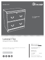
Lateral File
Heritae Hill Collection | 102702
Get all organized
and stu .

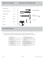
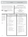
Table of Contents Assembly Tools Required
No. 2 Phillips Screwdriver
Tip Shown Actual Size
Hammer
Not actual size
2-3
4-5
6-22
23-25
26-28
29-30
31
Part Identifi cation
Hardware Identifi cation
Assembly Steps
Français
Español
Safety
Warranty
102702 www.sauder.com/servicesPae 2
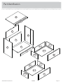
Part Identifi cation
å While not all parts are labeled, some of the parts will have a label or an inked letter on the ede
to help distinuish similar parts from each other. Use this part identifi cation to help identify similar parts.
A4 RIGHT END (1)
B3 LEFT END (1)
C3 TOP (1)
D LARGE BACK (1)
E2 BOTTOM (1)
F SMALL BACK (1)
G TOP MOLDING (1)
H3 UPPER DRAWER FRONT (1)
I3 LOWER DRAWER FRONT (1)
J BASE (1)
D61 DRAWER BACK (2)
D87 RIGHT DRAWER SIDE (2)
D88 LEFT DRAWER SIDE (2)
D729 DRAWER BOTTOM (2)
Tape Measure

Part Identifi cation
102702www.sauder.com/services
Pae 3
A4
D
D61
B3
C3
E2
F
G
H3
I3
J
D61
D87
D87
D88
D88
D729
D729

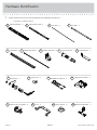
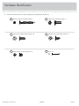
Hardware Identifi cation
å Screws are shown actual size. You may receive extra hardware with your unit.
(EXTENSION SET SHOWN SEPARATED)
EXTENSION RAIL - 4
O
EXTENSION SLIDE - 4
P
INTERLOCK TRACK - 1
T
FILE ROD - 4
Q
FILE BAR - 4
R
FILE GLIDE - 4
S
ANGLE BRACKET - 8
U
TOUCH-UP PEN - 1
V
JJ
TWIST-LOCK
®
FASTENER - 12
FILE BRACKET - 2
Y
AA
SLIDE CAM - 4
BB
DRAWER ACTUATOR - 2
PULL - 4
PP
PULL MOUNT - 8
QQ
29G
CABINET ACTUATOR - 2
REAR FILE BRACKET - 2
12B
LOCK PACK - 1
Z
102702 www.sauder.com/servicesPae 4

Hardware Identifi cation
å Screws are shown actual size. You may receive extra hardware with your unit.
BLACK 9/16" LARGE HEAD SCREW - 20
CC
EE
SILVER 5/8" MACHINE SCREW - 8
BROWN 7/16" LARGE HEAD SCREW - 8
DD
FF
GOLD 5/16" FLAT HEAD SCREW - 16
NAIL - 10
MM
102702www.sauder.com/services
Pae 5
30S
BLACK 1-9/16" FLAT HEAD SCREW -8

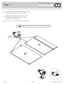
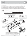
Step 1
Look for this icon. It means a
video assembly tip is available at
www.sauder.com/services/tips
å
Assemble your unit on a carpeted fl oor or on the empty
carton to avoid scratchin your unit or the fl oor.
å
To bein assembly, push a SAUDER TWIST-LOCK®
FASTENER (JJ) into the lare holes in the RIGHT
END (A4) and LEFT END (B3).
å
Repeat this step for the LARGE BACK (D) and BOTTOM (E2).
102702 www.sauder.com/servicesPae 6
JJ
A4
B3
(12 used)
Do not tihten the TWIST-LOCK® FASTENERS in this step.

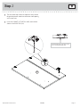
Step
å
The next three steps involve an important safety feature
desined to prevent more than one drawer from openin
at the same time.
å
Insert two CABINET ACTUATORS (29G) into the holes
shown in the RIGHT END (A4).
Step 2
102702www.sauder.com/services
Pae 7
A4
29G
This pin must insert into the location
holes in the RIGHT END (A4).

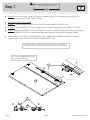
Step
å
Diaram 1. Cut out and use the "spacer" at the top of this pae to measure 2-1/2" from one end of the INTERLOCK
TRACK (T). Position the INTERLOCK TRACK as shown.
å
ACTUATOR / TRACK ATTACHMENT:
Diaram 2. Tilt the fi rst ede of the INTERLOCK TRACK (T) into the CABINET ACTUATOR (29G).
å
Diaram 3. Rotate the INTERLOCK TRACK and apply force to snap the second ede into the CABINET ACTUATOR.
å
Diaram 4. Repeat the ACTUATOR / TRACK ATTACHMENT for the next CABINET ACTUATOR while holdin the previously
completed CABINET ACTUATOR in its location hole. Repeat these steps until all ACTUATORS have been attached.
å
Visually check that all INTERLOCK TRACK edes have been snapped into the CABINET ACTUATORS as shown in
diaram 3. Then, remove the INTERLOCK TRACK assembly from the END.
Step 3
102702 www.sauder.com/servicesPae 8
T
29G
Cut out this rectanle to use as a "spacer"
2-1/2"
2-1/2"
29G
T
Do not slide the CABINET ACTUATORS
onto the INTERLOCK TRACK.
1.
2. 3.
4.
A4
The interlock system is a safety feature that prevents more than one drawer
from opening at the same time. Do not use excessive force to open the drawers.

Step
å
Separate the EXTENSION SLIDES (P) from the EXTENSION RAILS (O) as shown in the upper diaram below. Be prepared,
the parts are reasy.
å
Lay the INTERLOCK TRACK (T) and CABINET ACTUATORS (29G) in the roove of the RIGHT END (A4) as shown.
å
Fasten two EXTENSION RAILS (O) to each END (A4 and B3). Use eiht GOLD 5/16" FLAT HEAD SCREWS (FF).
å
NOTE: For each EXTENSION RAIL, turn a SCREW into the hole shown in the enlared diaram. Then, slide the inner cartride of the
EXTENSION RAIL out to fi nd the other hole that lines up with the hole in the END. Turn a SCREW into this hole.
å
NOTE: The EXTENSION SLIDES will be used later for the DRAWERS.
å
Fasten two ANGLE BRACKETS (U) to the ENDS (A4 and B3). Use two BLACK 9/16" LARGE HEAD SCREWS (CC).
å
NOTE: Be sure the edes of the ANGLE BRACKETS are even with the edes of the ENDS.
Step 4
102702www.sauder.com/services
Pae 9
U
U
O
O
O
O
A4
B3
T
29G
Finished ede
Open end
Finished ede
Open end
BLACK 9/16" LARGE HEAD SCREW
(2 used for the ANGLE BRACKETS)
CC
After fastenin the EXTENSION RAILS to the RIGHT END (A4), the
CABINET ACTUATOR should touch the top ede of the RAILS. If the ap is
larer than 1/16", the drawers could lock up and not open. If this happens,
open two drawers at the same time to override the interlock system.
Remove the drawers to re-adjust the INTERLOCK TRACK assembly.
GOLD 5/16" FLAT HEAD SCREW
(8 used for the RAILS)
FF
Surface with
TWIST-LOCK®
FASTENERS
Surface with
TWIST-LOCK®
FASTENERS
29G
O
Push the black lever in and pull the SLIDE from the RAIL.
P
O

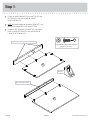
Step
å
Fasten six ANGLE BRACKETS (U) to the TOP (C3) and
BOTTOM (E2). Use six BLACK 9/16" LARGE
HEAD SCREWS (CC).
å
NOTE: Be sure the edes of the ANGLE BRACKETS are
even with the edes of the TOP and BOTTOM.
å
Fasten the TOP MOLDING (G) to the TOP (C3) and the
BASE (J) to the BOTTOM (E2). Use six BLACK 9/16"
LARGE HEAD SCREWS (CC).
Step 5
102702 www.sauder.com/servicesPae 10
U
C3
E2
G
J
This hole must be here.
(6 used)
These holes must be near the top ede.
BLACK 9/16" LARGE HEAD SCREW
(12 used in this step)
CC

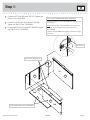
Step
å
Fasten the LEFT END (B3) to the TOP (C3). Tihten two
TWIST-LOCK® FASTENERS.
å
Fasten the LARGE BACK (D) to the LEFT END (B3).
Tihten two TWIST-LOCK® FASTENERS.
å
Fasten the BOTTOM (E2) to the LEFT END (B3). Tihten
two TWIST-LOCK® FASTENERS.
Step 6
102702www.sauder.com/services
Pae 11
B3
C3
D
E2
Dowel end
How to use the SAUDER TWIST-LOCK
®
FASTENER
1. Insert the dowel end of the FASTENER into the hole of the
adjoinin part.
NOTE: The dowel end of the FASTENER must remain fully
inserted in the hole of the adjoinin part while lockin
the FASTENER.
2. Tihten the FASTENER with a Phillips screwdriver as tiht
as possible.
Surface with TWIST-LOCK® FASTENERS
These holes must be here.
1st
2nd
3rd
G
J

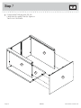
Step
å
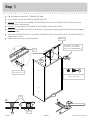
Fasten the RIGHT END (A4) to the TOP (C3),
LARGE BACK (D), and BOTTOM (E2). Tihten six
TWIST-LOCK® FASTENERS.
Step 7
102702 www.sauder.com/servicesPae 12
A4
C3
D
E2

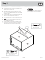
Step
å
Carefully turn your unit over onto its front edes. Lay the
SMALL BACK (F) over your unit.
å
Make equal marins alon all four edes of the SMALL
BACK (F). Push on opposite corners of your unit if needed
to make it "square".
å
Fasten the SMALL BACK (F) to the LARGE BACK (D). Use
four BLACK 9/16" LARGE HEAD SCREWS (CC)
å
Fasten the SMALL BACK (F) to your unit usin the NAILS (MM).
å
NOTE: Be sure the notched ede of the SMALL BACK is
alon the top ede of your unit.
å
Fasten the BASE (J) to the ENDS (A4 and B3). Use two
BLACK 9/16" LARGE HEAD SCREWS (CC) throuh the
ANGLE BRACKETS on the ENDS and into the BASE.
Step 8
102702www.sauder.com/services
Pae 13
F
D
J
A4
B3
Do not stand the unit upriht without the
BACK fastened. The unit may collapse.
Caution
NAIL
(10 used in this step)
MM
CC
BLACK 9/16" LARGE HEAD SCREW
(6 used in this step)
CC
Notch

Step Step 9
102702 www.sauder.com/servicesPae 14
VIEW THE T-LOCK BOX VIDEO
å
Fasten the DRAWER BACK (D61) to the DRAWER SIDES (D87 and D88). Use four BLACK 1-9/16" FLAT HEAD SCREWS (30S).
å
NOTE: Be sure the DRAWER BOTTOM (D729) inserts into the roove of the DRAWER BACK (D61).
å
Repeat this step for the remainin drawer usin the LOWER DRAWER FRONT (I3).
12
3
å
Insert the DRAWER SIDES (D87 and D88) at
an anle into the slot at each end of the UPPER
DRAWER FRONT (H3).
å
Slide the DRAWER BOTTOM (D729) into the rooves
in the DRAWER SIDES (D87 and D88) and UPPER
DRAWER FRONT (H3).
The tabs should insert freely
into the slots. Gently tilt the
DRAWER SIDES side to side
until the tabs slip into the slots.
Groove
Start each screw a few turns before
completely tihtenin any of them.
BLACK 1-9/16" FLAT HEAD SCREW
(8 used in this step)
30S
Be sure the DRAWER
BOTTOM inserts into the
DRAWER FRONT roove.
D88
D87
D729
D61
H3
Unfi nished
surface
With the palm of your
hand, tap the DRAWER
BOTTOM down into
the roove.
D88
D87
H3
D88
D87
D729

Step
å
Insert a SLIDE CAM (AA) into the LEFT DRAWER SIDE (D88).
å
Fasten an EXTENSION SLIDE (P) to a LEFT DRAWER
SIDE (D88). Use two GOLD 5/16" FLAT HEAD
SCREWS (FF) throuh holes #1 and #4.
å
NOTE: The screw head in the CAM must be visible
throuh the slotted hole in the SLIDE.
Step 10
102702www.sauder.com/services
Pae 15
P
AA
4
Screw head - turn CAM to line up holes in
the SLIDES with holes in DRAWER SIDES
1
2
3
Open end
D88
D87
GOLD 5/16" FLAT HEAD SCREW
(4 used in this step)
FF

Step
å
Flip the drawer over onto the LEFT DRAWER SIDE (D88).
å
Insert a SLIDE CAM (AA) into the RIGHT DRAWER SIDE (D87).
å
Diaram 1. Insert the tabs on a DRAWER ACTUATOR (BB) into the slots in a EXTENSION SLIDE (P). You may need to
insert one tab fi rst, then the other.
å
Diaram 2. Visually check that the DRAWER ACTUATOR (BB) is seated in the SLIDE (P).
å
Diaram 3. If the DRAWER ACTUATOR is not seated, use your hammer to ently tap the SLIDE until the tabs are properly
seated in the slots.
å
Now, fasten the EXTENSION SLIDE (P) to the RIGHT DRAWER SIDE (D87). Use two GOLD 5/16" FLAT HEAD SCREWS (FF)
throuh holes #1 and #4.
å
Repeat steps 10 and 11 for the remainin drawer.
Step 11
102702 www.sauder.com/servicesPae 16
BB
BB
P
2.
3.
Post
Seated
AA
Screw head - turn CAM to
line up holes in the SLIDES
with holes in DRAWER SIDES
P
4
1
2
3
D88
D87
GOLD 5/16" FLAT HEAD SCREW
(4 used in this step)
FF
1.
BB
P
These tabs must
insert into the slots.
Slot
Open end

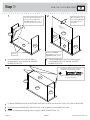
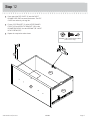
Step
å
Press one of the FILE GLIDES (S) over the RIGHT
DRAWER SIDE (D87) on one of the drawers. The FILE
GLIDES are necessary to han fi les.
å
Fasten a FILE BRACKET (Y) to the UPPER DRAWER
FRONT (H3) and REAR FILE BRACKET (12B) to the
DRAWER BACK (D61). Use four BROWN 7/16" LARGE
HEAD SCREWS (DD).
å
Repeat this step for the other drawer.
Step 12
102702www.sauder.com/services
Pae 17
Y
H3
S
D87
12B
BROWN 7/16" LARGE HEAD SCREW
(8 used in this step)
DD
D61

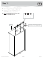
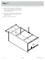
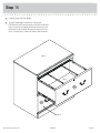
Step
å
Slide the FILE RODS (Q) throuh a FILE BAR (R), throuh
the holes in the FILE BRACKETS (Y and 12B), throuh
another FILE BAR (R), and into the FILE GLIDE (S) on the
RIGHT DRAWER SIDE (D87).
å
Slide another FILE GLIDE (S) onto the other end of the
FILE RODS (Q), then press this FILE GLIDE over the LEFT
DRAWER SIDE (D88).
å
Repeat this step for the other drawer.
Step 13
102702 www.sauder.com/servicesPae 18
Q
Q
R
R
S
S
D87
12B
D88

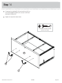
Step
å
Fasten four PULL MOUNTS (QQ) and two PULLS (PP) to
the UPPER DRAWER FRONT (H3). Use four SILVER 5/8"
MACHINE SCREWS (EE).
å
Repeat this step for the other drawer.
Step 14
102702www.sauder.com/services
Pae 19
SILVER 5/8" MACHINE SCREW
(8 used in this step)
EE
H3
QQ
PP

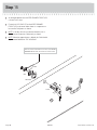
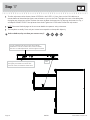
Step
å
An enlared portion of the UPPER DRAWER FRONT (H3)
is shown in this step
å
Fasten the LOCK PACK (Z) to the UPPER DRAWER
FRONT (H3) in the exact order shown. It is important to
be sure the CAM points as shown.
å
NOTE: If the key will not turn counter-clockwise, turn it
clockwise and fasten the CAM exactly as shown.
å
NOTE: When the upper drawer is locked, the CAM should
be positioned behind the TOP MOLDING.
Step 15
102702 www.sauder.com/servicesPae 20
H3
CAM
NUT
WASHER
LOCK
SCREW
Z
This end of the CAM must be closer to the UPPER
DRAWER FRONT than the other end of the CAM.
La page est en cours de chargement...
La page est en cours de chargement...
La page est en cours de chargement...
La page est en cours de chargement...
La page est en cours de chargement...
La page est en cours de chargement...
La page est en cours de chargement...
La page est en cours de chargement...
La page est en cours de chargement...
La page est en cours de chargement...
La page est en cours de chargement...
La page est en cours de chargement...
-
 1
1
-
 2
2
-
 3
3
-
 4
4
-
 5
5
-
 6
6
-
 7
7
-
 8
8
-
 9
9
-
 10
10
-
 11
11
-
 12
12
-
 13
13
-
 14
14
-
 15
15
-
 16
16
-
 17
17
-
 18
18
-
 19
19
-
 20
20
-
 21
21
-
 22
22
-
 23
23
-
 24
24
-
 25
25
-
 26
26
-
 27
27
-
 28
28
-
 29
29
-
 30
30
-
 31
31
-
 32
32


Sauder Heritage Hill Lateral File 102702 Manuel utilisateur
- Taper
- Manuel utilisateur
dans d''autres langues
Documents connexes
-
Sauder 415109 Manuel utilisateur
-
-
-
-
-
-
-
-
-

