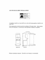
Maytag MDG Series Installation Instructions Manual
- Catégorie
- Sèche-linge électriques
- Taper
- Installation Instructions Manual
Ce manuel convient également à

MDG (ALL)
INSTALLATION
INSTRUCTIONS

PLEASE READ ALL INSTALLATION INSTRUCTIONS AND REQUIREMENTS BEFORE INSTALLING.
AWARNING: For your safety the information in this
manual must be followed to minimize the risk of fire
or explosion or to prevent property damage, personal
injury or loss of life.
• Do not store or use gasoline or other flammable
vapors and liquids in the vicini'(y of this or any
other appliance.
WHAT T.O DO IF YOU SMELL GAS
• Do not try to light any appliance.
• Do not touch any electrical switch; do not use any
phone in your building.
• Clear the room, building or area of all occupants.
• Immediately call your gas supplier from a neigh-
bor's phone. Follow the gas supplier's instructions.
• If you cannot reach your gas supplier, call the fire
department.
Installation and service must be performed by a quali-
fied installer, service agency or the gas supplier.
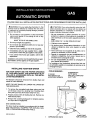
INSTALLING YOUR NEW DRYER
FOR YOUR SAFETY AND THE PROPER OPERATION
OF YOUR NEW DRYER, THE DRYER MUST BE IN-
STALLED IN ACCORDANCE WITH ALL THE INSTAL-
LATION REQUIREMENTS.
All literature should be removed from inside dryer and
saved for future reference.
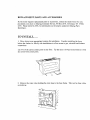
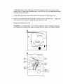
NOTE: DO NOT RAISE OR LOWER THE DRYER BY
THE BACKGUARD.
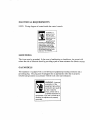
1. To remove the corrugated crate base, place your foot
on the base close to a leveling foot. Pushing down
firmly with your foot, tilt the dryer away from you.
2. Repeat process with all leveling feet (4). Remove ex-
cess base by hand.
3. Remove film covering backguard for shipping purpos-
es. Wipe clean of fingerprints.
GAS CONNECTIONS
The dryer must be installed in accordance with the Instal-
lation Requirements. EQUIPPED FOR NATURAL GAS.
FOR LP GAS INSTALLATION SEE PAGE 2.
PiN 53-2593-5
_ATTENTION: Pour votre s_curit6, suivre les indi-
cations donn6es dans ce manuel afin de r_duire les
risques d'incendie ou d'explosion et d'_viter dom-
mages materiels, blessures et d6c_s.
- Ne pas entreposer ni utiliser d'essence ou autres
produits et vapeurs inflammables & proximit6 de
cette s_cheuse ou de tout autre appareil _lectrome-
nager.
- QUE FAIRE S'IL Y A UNE ODEUR DE GAZ
• N'allumer aucun appareit.
• Ne toucher aucun commutateur _lectrique; ne pas
utiliser le t616phone dans votre maison ou votre
immeuble.
• Faire sortir tousles occupants de la piece, du to-
gement ou immeuble, ou de la vicinit6.
• Appeler la compagnie de gas imm_diatement en
utilisant le t_l_phone d'un voisin. Suivre les in-
structions de la compagnie de gaz.
• En cas d'impossibilit_ de joindre la compagnie de
gaz, appeler les pompiers.
Le montage et les r_parations doivent _tre faits par
un technicien qualifi_, un prestataire de services ou la
compagnie de gaz.
- TOOLS REQUIRED -
'/," DRIVER
PIPE WRENCH OR
ADJUSTABLE WRENCH
SCREWDRIVER
PUTTY KNIFE
PIPE SEAL COMPOUND
DUCT TAPE
/ BACKGUARD
_ PLAICE FOOT
CORRUGATED CRATE FOR LEVERAGE

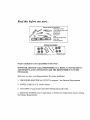
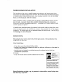
Read this before you start...
TOOLS needed for installation
Joint Compound (gas on_y)
•Cutting Knife
S( _= <_ .Pipe Wrench
•Nut Drivers
*Level
•Screw Driver (Standard)
•Duct Tape
•Crescent Wrench
ITEMS PROVIDED
@@ X @@
Electric Dryer OnLy Gas Dryer Oniy
Proper installation is the responsibility of the owner.
HOWEVER, SERVICE CALLS PERFORMED AS A RESULT OF POOR SETUP,
ADJUSTMENT, AND CONNECTION ARE THE RESPONSIBILITY OF THE
INSTALLER.
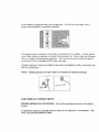
Make sure you have everything necessary for proper installation
!. GROUNDED ELECTRICAL OUTLET is required. See Electrical Requirements.
2. POWER CORD for U.S. electric dryers.
3. GAS LINES (if a gas dryer) must meet National and Local Codes.
4. EXHAUST SYSTEM must be rigid'metal or flexible stiff walled metal exhaus_ ducting.
See Exhaust Requirements.

mt mum
i_._ Base Exhaust
_!=_minimum
-T
,l,
IMPORTANT TO INSTALLER
PLEASE READ TIlE FOLLOWING INSTRUCTIONS CARSEFUT._LY BEFORE
STARTING TO INSTALL TI_ DRYER. THESE INSTRUCTIONS SHOL_LD BE
RETAINED FOR FUTURE REFERENCE.
REMOVE THE DOOR FROM ALL DISCARDED APPLIANCES SUCH AS DRYERS
TO AVOID THE DANGER OF A CHILD SUFFOCATING.
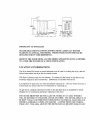
LOCATION CONSIDERATIONS
The dryer should be located to permit adequate room in front for loading the dryer, and suf-
ficient room behind the dryer for the exhaust system.
This dryer is factory-ready for rear exhaust. To exhaust out the bottom or left side use the
accessory exhaust kit (see Accessories). Instructions are included win the kit.
It is important to make sure the room has adequate make-up air. The area where the dryer is
located must not obstruct the flow of combustion or ventilating air.
On gas dryers, adequate clearance as noted on the data plate must be maintained to insure
adequate air for combustion and proper operation of the dryer.
THE DRYER MUST NOT BE INSTALLED OR STORED IN AN AREA WHERE IT
WILL BE EXPOSED TO WEATHER AND/OR WEATHER. THE DRYER AREAS IS TO
BE KEPT CLEAR AND FREE FROM COMBUSTIBLE MATERIALS, GASOLINE AND
OTHER FLAMMABLE VAPORS AND LIQUIDS. A DRYER PRODUCES COMBUS-
TIBLE LINT, THE AREA AROUND THE DRYER SHOULD BE KEPT FREE OF LINT.

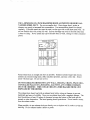
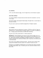
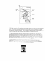
ALCOVE OR CLOSET INSTALLATION
WARNING - The
dryer must be ex-
hausted to the
outside to reduce the
risk of fire when
installed in an alcove
or closet.
An appliance installed in a closet shall have no other fuel-burning appliance installed in the
same closet.
Each opening area in the door must have a minimum of 36 square inches. These openings
must not be obstructed. (Louvered door with equivalent air opemng is acceptable).
o2.
olo
-f
17"
8°_° ©_k
_2
0"
L,
FRONT VIEW
CLOSET DO_R_
L
2"
SIDE VIEW
]÷ --36 S_
inch
--36 s
Inch
Minimum installation clearances. If possible, more clearance is recommended

MOBILE HOME INSTALLATION
The installation of the dryer in mobile homes must conform to the Manufactured Home
Construction and Safety Standard Title 24 CFR, Part 32-80 (formerly the Federal Standard
for Mobile Home Construction and Safety, TNe 24 HUD (Part 280), 1975 for the United
States), or CSA Standards Z240 (for Canada).
When installing a dryer in a mobile home, provisions for anchoring the dryer to the floor
must be made. An anchor bracket kit is available with instructions (see Accessories).
Locate in an area that has adequate makeup air. A minimum of 25 square inches of unob-
structed opening is required.
All mobile home installations must be exhausted to the outside with the exhaust duct termi-
nation securely fastened to the mobile home structure, using materials that will not support
combustion. The exhaust duct may not terminate beneath the mobile home. See the section
on exhausting for more information.
EXHAUSTING
Exhausting the dryer to the outside will prevem large amounts of tint and moisture from
being blown into the room.
In the United States:
- all gas dryers must be exhausted to the outside
- electric dryers located in a confined area such as a bedroom, bathroom, or closet must be
exhausted to the outside.
- electric dryers not located in a confined area may be exhausted to the inside (see
nonexhausted installations).
In Canada:
- all gas and electric dryers must be exhausted to the outside.
WARNING -
plastic or nonmetal
ftexibte duct pre-
sents a potential fire
hazard.
NEVER USE PLASTIC
NON METAL FLEXIBLE DUCT.
If your existing ductwork is p_astio,
nonmetal or combustible, reptace
it with metal. Use onty metal
exhaust duct that wilt not support
combustion to insure the cantain-
merit of exhaust air, heat and iint.
Plastic flexible duct can kink, sag, be punctured, reduce airflow, extend drying times,
and affect dryer operation.

USE A MIN/MUM OF 4 INCH DIAMETER RIGID ALUM!NqJM OR RIGID GAL-
VANIZED STEEL DUCT. Do not use smaller duct. Ducts larger than 4 inches in
diameter can result in increased lint accumulation. Lint accumulation should be cleaned
regularly. If flexible metal duct must be used, use the type with a stiff sheet metal wall. do
not use flexibIe duct with a thin foiI wall. Serious blockage can result if flexible metal duct
is bent too sharp. Never install any type of flexible duct in walls, ceilings or other concealed
places.
EXHAUST HOOD"?YPE
90* Turns
i"'M_Lximumlengm of 4qnch diameter
rigid metal duct.
0 BSff- 59ft.
1 54ft 48ft,
2 44ft. 38ft
3 36 ft, 30 ft.
4 28f!', 22ft.
Maximum length of 4-inch diameter
flexfbte stiff waited merci _uct,
0 36ft. 28ft,
1 32_t. 24_.
2 28ft. 20ft.
3 25ft. 17ff.
4 23fL 15ft.
Keep exhaust duct as straight and short as possible. Exhaust systems longer than recom-
mended can extend drying times, affect machine operation, and may collect lint. Secure
joints with duct tape. Do not use screws.
DO NOT EXHAUST DRYER INTO ANY WALL, CEILING, CRAWL SPACE OR A
CONCEALED PLACE OF A BUILDING, GAS VENT, ANY OTHER COMMON
DUCT OR CtIIMNEY. THIS COULD CREATE A FIRE HAZARD FROM LINT
EXPELLED BY THE DRYER.
The exhaust duct should end with an exhaust hood with a swing out damper to prevent
backdrafts and entry of wildlife. Never use an exhaust hood with a magnetic damper. The
hood should have a least 12 inches of clearance between the bottom of the hood and the
ground or other obstruction. The hood opening should point down. Never install a screen
over the exhaust outlet.
Wqaen possible, do not exhaust the dryer directly over a window welt in order to avoid tint
build-up. Do not exhaust under a house or porch.

GAS REQUIREMENTS
Use only Natural or LP gases.
THE INSTALLATION MUST CONI_ORM WITH LOCAL CODES, OR IN THE
ABSENCE OF LOCAL CODES, WITH THE NATIONAL FUEL GAS CODE
ANSI/Z223.1, LATEST REVISION (FOR THE UNITED STATES), OR WITH TIlE
CAN/CGA-B149 INSTALLATION CODES (FOR CANADA).
Gas dryers are equipped with a burner orifice for operation on NATURAL gas. If the dryer
is to be operated on LP (liquid propane) gas, it must be convened for safe and proper per-
formance and must be converted by a qualified service technician, conversion kits from
NATURAL to LP, or LP to NATURAL are available through you local Maytag dealer (see
Accessories). If other conversions are required, check with the local gas utility for specific
information concerning conversion requirements.
A t/2" gas supply line is recommended and must be reduced to connect to the 3/8" gas line
on the dryer.
The National Fuel Gas Code requires that an acceptable, approved manual gas shut off valve
be installed within 6 feet of the dryer.
Additionally, a 1/8" N.P.T (National Pipe Thread) plugged tapping, accessible for test gauge
connection, must be installed immediately upstream of the gas supply connection to the
dryer.
The dryer must be disconnected from the gas supply piping system during any pressure test-
ing of the system.
DO NOT re-use old flexible metal gas line. Flexible gas line must be design certified by
American Gas Association (CGA in Canada). NOTE: Any pipe joint compound used must
be resistant to the action of any liquefied petroleum gas,
NOTE: As a courtesy, most local gas utilities will inspect a gas appliance installation.
GAS IGNITION
This dryer uses an automatic ignkion system to ignite the burner. There is no constant
burning pilot.

ELECTRICAL REQUIREMENTS
NOTE: Wiring diagram is located inside the control console.
WARNING - To
prevent urlr_ecas-
sary risk of fire,
electrical shock or
personal injury, all
wiring and
grounding must
be done in accordance with
focal codes, or in the absence
of local codes, with the Na_
tional Electrical Code, ANSI/
NFPA (for the Untted States) or
the Canadian Electrical code
CSA C22,1 (for Canada).
GROENDING
This dryer must be grounded. In the event of malfunction or breakdown, the ground wilI
reduce the risk of electrical shock by providing a path of teast resistance for electric current.
GAS MODELS
This appliance is equipped with a cord having an equipment-grounding conductor and a
grounding pIug. The ptug must be pIugged into an appropriate outlet that is properly
installed and grounded in accordance with all loca! codes and ordinances.
WARNING- Improper
connection of the
equipment grounding
conductor can result in
a risk or electric
shock. Check with a
qualified electrician or
serviceman if you are in doubt as to
whether the appliance is properly
grounded,

Do not modify the plug provided with the appliance - if k will not fit the outlet, have a
proper outlet installed by a qualified electrician.
K a separate round is required by local codes, an accessory kit is available. Connect ground
wire to back of unit by using the wire found in the accessory kit. Secure other end of ground
wire to a suitable external ground connection. The wire may be secured with the clamp (in
the accessory kit) to a grounded COLD metal water pipe.
NEVER CONNECT GROUND WIRE TO PLASTIC PLUMBING LINES, GAS LINES OR
HOT WATER PIPES.
NOTE: Cabinet ground screw and washer are found in the customer package.
ELECTRICAL CONNECTIONS
BEFORE OPERATING OR TESTING, follow all grounding instructions in Grounding
Section.
An individual branch (or separate) circuit serving only this appliance is recommended. DO
NOT USE AN EXTENSION CORD.

Do notmodify theplugprovided with theappliance- if it will notfit theoutlet, havea
properoutletinstalledby a qualifiedelectrician.
If a separateroundis requiredby local codes,anaccessorykit isavailable. Connectground
wire to backof unit by usingthewire found intheaccessorykit. Secureother endof ground
wire to a suitableexternalgroundconnection. Thewire maybesecuredwith theclamp(in
theaccessorykit) to agroundedCOLD metalwaterpipe.
NEVER CONNECT GROUND WIRE TO PLASTIC PLUMBING LINES, GASLINES OR
HOT WATER PIPES.
NOTE: Cabinet ground screw and washer are found in the customer package.
ELECTRICAL CONNECTIONS
BEFORE OPERATING OR TESTING, follow all grounding instructions in Grounding
Section.
An individua! branch (or separate) circuit serving ortly this appliance is recommended. DO
NOT USE AN EXTENSION CORD.

GAS MODELS
A 120 volt, 60 Hz electrical supply, with a 15 ampere fuse or circuit breaker is required.
ELECTRIC MODELS
To avoid the possibility of electrical shock, the dryer must not be connected to a 120 volt
2-wire circuit.
The electrical supply circuit should be fused through a 30 ampere fuse or circuit breaker on
both sides of the line.
If a power cord is used, the cord should be plugged into a 30 ampere receptacle.
U.S. MODELS
Maytag eIectric dryers are manufactured to operate on 120/240 volt, 60 Hz AC approved
electrical service. The dryer must be converted to operate on a 120/208 volt electrical sys-
tem. A heating element conversion kit is available (see Accessories).
The power cord is NOT provided with U.S. electric model dryers.
IMPORTANT: When permitted by local codes, the dryer electrical supply may be con-
nected by means of a new power supply cord kit, marked for use with clothes dryer, that is
U.L. listed, rated at 120/240 volts minimum, 30 amperes with three No. 10 copper wire
conductors terminated with closed loop terminals, open end spade lugs with turned up ends
or with tinned leads.
Do not reuse a power supply cord from an old dryer. The power cord or electric supply
wiring must be retained at the dryer cabinet with a suitable UL listed strain relief.
If the dryer is to be installed in a mobile home or an area where local codes do not permit
grounding through neutral, only a 4 conductor power cord, rated and terminated as above,
may be used.

CANADIAN MODELS
All Canadian models are shipped with the power cord attached.
NOTE: It is not permissible to convert a dryer in Canada to 208 volts.
ADDITIONAL INFORMATION - 50 HERTZ OPERATION
This Maytag dryer model is manufactured for operation on 60 Hz AC approved electrical
service. This model is not designed for use on 50 Hz AC electrical service and conversion of
the product from 60 to 50 HZ operation is not recommended. For additional information on
50 Hz products, write
MAYTAG INTERNATIONAL, INC.
8700 BRYN MAWR AVE.
CHICAGO, IL 60631
Phone 773-714-0100
INSTALLATION ACCESSORIES
- Vent Hood - 4" (10.!6 cm) opening
- Aluminum Pipe - 4" x 24" (10.16 cm x 60.96 cm) ,
- Aluminum Elbow - 4" (10.16 cm)
- Aluminum Window Plate - I5" x 20" (38.10 cmx 50.80 cm) - 4" (10.16 cm) hole
- Exhaust Deflector Kit. (U.S. Electric Models Only)
- Flexible Aluminum Vent Duct - 4" (10.16 cm diameter - 38" (81.28 cm) length stretches to
8' (2.44 cm)
- Clamp for Flexible Aluminum Duct
- Exhaust Duct Kit for Base or Left Side Exhausting
- Dacron Lint Bag
- Bracket for Exhaust Deflector
- Rectangular Vent Kits
- NaturaI to LP Conversion Kit
- LP to Natural Conversion Kit
- Anchor Bracket Kit
- Heating Element Conversion Kit.
- Exhaust Kit
- Grounding Kit

REPLACEMENT PARTS AND ACCESSORIES
If your dryer requires replacement parts or accessories, contact the dealer from who you
purchased your dryer or Maytag Customer Service, PO Box 2370, Cleveland, TN 37320-
2370. Phone 423-472-3333, for information on the nearest authorized Maytag Parts
Distributor.
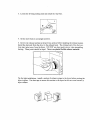
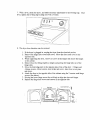
TO INSTALL .....
1. Move dryer to an appropriate location for installation. Consider installing the dryer
before the washer in side by side installations to allow access to gas, electrical and exhaust
connections.
Lay two of the carton comer posts on the floor. Tip the dryer forward on its front so it will
lay across both corner posts.
2. Remove the crate wires holding the cr.ate base to the base frame. This can be done with a
screwdriver:

3. Loosen the leveling locking nuts and install the vinyl feet.
4. Set the dryer back in an upright position.
5. Review the exhaust section in the previous section before installing the exhaust system.
Install the ductwork from the dryer to the exhaust hood. The crimped end of the duct sec-
tions must point away from the dryer. DO NOT use sheet recta1 screws when assembling
ducting. These joints should be taped. Never use plastic flexible exhaust material.
Tip for tight installations: install a section of exhaust system to the dryer before moving the
dryer in pIace. Use duct tape to secure this section to the dryer but do not cover louvers in
dryer cabinet.

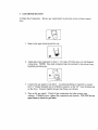
6. GAS DRYER SECTION
To Make Gas Connection - Review gas requirements in previous section of these instruc-
tions.
1. Remove the pipe thread protective cap.
,
Apply pipe joint compound or about 1 1/2 wraps of Teflon tape over atl threaded
connections. NOTE: Pipe joint compound must be resistant to the action of an},
liquefied petroleum gas.
.
,
Connect the gas supply to the dryer. An additional fitting is required to connect
the 3/4" female threaded end of a flexible connector to the 3/8" male threaded end
on the dryer. Securely tighten the gas line fitting over threads.
Turn on the gas supply. Check all gas connections for leaks using a soap
solution. If bubbles occur, tighten the connections and recheck. DO NOT use an
open flame to check for gas leaks.

ELECTRIC DRYER SECTION
To Make the Electrical Connection - Review the electrical requirements in the previous sec-
tion of these instructions.
IMPORTANT - The dryer frame is grounded to the neutral conductor at the terminal block.
If the dryer is installed in a mobite home, or if local codes do not permit grounding through
the neutral, refer to 4 WIRE SYSTEM CONNECTION.
Remove the terminal block cover plate.
Insert the power cord with a U.L. listed strain relief through the hole provided in the cabinet
near the terminal block. Note:.a strain relief must be used.
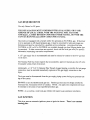
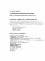
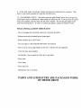
3-WIRE SYSTEM CON2qECTIONS
Do not loosen the nuts already installed on the terminal block. Be sure they are tight. Use a
3/8" deep well socket.
If the power cord has terminals, place the terminals over the existing nuts on the posts. The
neutral (white or center wire on the power cord) conductor must always be connected to the
center (silver colored) post of the terminal block.
Secure in place using the nuts provided in the accessories package. If the power cord does
not have terminals, use the cupped washer ahead of the nuts.
Be sure the terminal block nuts are tight. Secure the power cord in position. Tighten the
strain relief screw(s) in order to clamp the strain relief to the cord.
Replace the terminal block cover.
BEFORE OPERATING OR TESTING, follow the ground directions in the previous sec-
tion.
WARNING: If converting from a 4-wire electrical system to a 3-wire, the ground
strap must be reconnected to the terminal block support to ground the dryer frame to
the neutral conductor.
4-WIRE SYSTEM CONNECTION
Remove the ground strap screw from the terminal block support. Fold the ground strap over
so both ends of the ground strap are attached to the center terminai block post.

Connect the neutral (white) conductor of the cord to the center (silver colored) post of the
terminal block. Connect the grounding (green) wire of the cord to the terminal block support
using the ground strap screw.
Connect the red and black wires of the cord to the outer posts of the terminal block.
Be sure the termini block nuts are on tight. Secure the power cord in position. Tighten the
strain relief screw(s) in order to clamp the strain relief to the cord.
Replace the terminal block cover.
WARNING: If converting from 4-wire electrical systems to 3-wire, the ground strap must
be reconnected to terminal block support to ground the dryer flame to the neutral conductor
A
/
Terminal Block
Cover Plate
B
Terminal
Block "_
Terminal
Block ._
Suppor_
C)
o
3-Wire System
/
Ground
Strap
/
Ground
Strap
Screw
Hole for
power cord
_" and
strain relief

Neutral
Post _..
C
3-Wire System
o
/
Ground
Strap
/
/ Neutral
Stra;n
/ Relief
- krnproper connection of the equipment -grounding conductor can result in a risk of electrical
shock. Check with a qualified electrician or service man if you are in doubt as to whether
the appliance is properly grounded. Do not modify the plug provided with the appliance - if
it will not fit the outlet, have a proper outlet installed by a qualified electrician.
- To prevent unnecessary risk of fire, electrical shock or personal injury, all wiring and
grounding must be done in accordance with the National Electrical Code ANSI/NFPA, No.
70-Latest Revision (for U.S,) or the Canadian Electrical Code CSA C22.1-Latest Revision
and local codes and ordinances. It is the personal responsibility and obligation of the appli-
ance owner to provide adequate electrical services for this appliance.
- All gas installations must be done in accordance with the National Fuel Gas Code
ANSI/Z223.1-Latest Revision (for the United States) or the CANiCGA-B149 Installation
Codes-Latest Revision (for Canada) and local codes and ordinances.

7. With alevel, checkthe dryer, andmakenecessaryadjustmentsto thelevelinglegs. Once
level, tightenthelevelingleg locking nutswith awrench.
8. Thedryer doordirection canbereversed.
1. If thedryer is pluggedin, unplug thedryerfrom theelectricalservice.
2. Removethehingehole coversandcrews. Movethedoorcatchcoverto the
oppositeside.
3. While supportingthe door, remove2 screwsin the hinges that secure the hinges
to the cabinet.
4. Remove door by lifting slightly at kinges and pulling the hinge tabs out of the
hinge slots.
5. Move the following parts to the opposite side of the of the door: 2 hinges and
4 hinge screws, 4 door screws, door strike and screw, kmer door cover plate
and screw.
6. Attach the door to the opposite side of the cabinet using the 2 counter sunk hinge
screws (See below).
7. Driving the lower hinge screw first wilt help to align the door and hinges.
8. Replace the hinge hole covers and screws in the opposite side.
La page charge ...
-
 1
1
-
 2
2
-
 3
3
-
 4
4
-
 5
5
-
 6
6
-
 7
7
-
 8
8
-
 9
9
-
 10
10
-
 11
11
-
 12
12
-
 13
13
-
 14
14
-
 15
15
-
 16
16
-
 17
17
-
 18
18
-
 19
19
-
 20
20
-
 21
21


Maytag MDG Series Installation Instructions Manual
- Catégorie
- Sèche-linge électriques
- Taper
- Installation Instructions Manual
- Ce manuel convient également à
dans d''autres langues
- English: Maytag MDG Series