
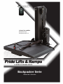
MOBILITY MADE EASY. LA MOBILITE RENDUE FACILE.
Backpacker Series
Backpacker Serie
Owner’s Manual • Manuel de l’utilisateur
Including Models
Incluant les modèles
Backpacker Plus
Backpacker AVP 2.0
Available only on:
Backpacker AVP 2.0
Disponible avec:
Backpacker AVP 2.0
RF Wireless Pendant
Pendentif Sans Fil RF

WARNING! An authorized Pride Provider or a qualified technician must perform the initial setup of
this product and must perform all of the procedures in this manual.
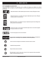
The symbols below are used throughout this owner’s manual and on the product to identify warnings and
important information. It is very important for you to read them and understand them completely.
WARNING! Indicates a potentially hazardous condition/situation. Failure to follow designated
procedures can cause either personal injury, component damage, or malfunction. On the product,
this icon is represented as a black symbol on a yellow triangle with a black border.
MANDATORY! These actions should be performed as specified. Failure to perform mandatory actions
can cause personal injury and/or equipment damage. On the product, this icon is represented as a
white symbol on a blue dot with a white border.
PROHIBITED! These actions are prohibited. These actions should not be performed at any time or
in any circumstances. Performing a prohibited action can cause personal injury and/or equipment
damage. On the product, this icon is represented as a black symbol with a red circle and red slash.
CALIFORNIA PROPOSITION 65 WARNING! This product is equipped with batteries that contain lead
and lead components and other chemicals which are known to the state of California to cause cancer
and birth defects or other reproductive harm. For more information, go to www.P65Warnings.ca.gov.
Intended Use
The intended use of the Pride Mobility Products device is to aid in the transport of products that provide
mobility to persons limited to a seated position that have the capability of operating a mobility device.
NOTE: This owner’s manual is compiled from the latest specifications and product information
available at the time of publication. We reserve the right to make changes as they become
necessary. Any changes to our products may cause slight variations between the illustrations
and explanations in this manual and the product you have purchased. The latest/current version
of this manual is available on our website.
NOTE: This product is compliant with WEEE, RoHS, and REACH directives and requirements.
NOTE: This product meets IPX4 classification (IEC 60529).
NOTE: The Backpacker Series Lift System and its components are not made with natural rubber
latex. Consult with the manufacturer regarding any after-market accessories.
Quick Reference Information
Pride Provider:
Address:
Phone Number:
Purchase Date:
Copyright © 2018
INFMANU3698/Rev G/May 2018
SAFETY GUIDELINESSAFETY GUIDELINES

Backpacker Series www.pridemobility.com 3
CONTENTS
I. INTRODUCTION .......................................................................................................................................4
II. SAFETY ......................................................................................................................................................5
III. INSTALLATION .........................................................................................................................................9
IV. OPERATION ............................................................................................................................................14
V. TROUBLESHOOTING ...........................................................................................................................20
VI. CARE AND MAINTENANCE ................................................................................................................21
VII. WARRANTY .............................................................................................................................................23

4 www.pridemobility.com Backpacker Series
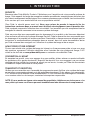
I. INTRODUCTION
SAFETY
Welcome to Pride Mobility Products (Pride). Congratulations on the purchase of your new lift system.
The lift system design combines the most advanced state-of-the-art components with modern, attractive
styling. We are certain that the design features and trouble-free operation will add convenience to your
daily living and ensure complete satisfaction.
At Pride, your safety is important to us. Please read and follow all instructions in this manual before
operating your lift system for the first time. These instructions were produced for your benefit. Your
understanding of these instructions is essential for the safe operation of your new lift system.
Pride is not liable for damage to property or personal injury arising out of the unsafe use of a lift
system. Pride is also not liable for any property damage or personal injury arising out of the failure of
any person and/or user to follow the instructions and recommendations set forth in this manual or any
other instructions or recommendations contained in other lift system related literature issued by Pride
or contained on the lift system itself.
INTERNET AND PRIVATE PURCHASES
If you purchased your product over the Internet or from a previous owner and you have any questions
about the safe use and/or maintenance of the product, please visit our web site www.pridemobility.com
or contact your authorized Pride Provider.
PURCHASER’S AGREEMENT
By accepting delivery of this product, you promise that you will not change, alter, or modify this product
or remove or render inoperable or unsafe any guards, shields, or other safety features of this product;
fail, refuse, or neglect to install any retrofit kits from time to time provided by Pride to enhance or
preserve the safe use of this product.
SHIPPING AND DELIVERY
Before using your lift system, make sure your delivery is complete as some components may be
individually packaged. If you do not receive a complete delivery, please contact your authorized Pride
Provider immediately. Where damage has occurred during transport, either to the packaging or content,
please contact the delivery company responsible.
NOTE: If you ever lose or misplace your copy of this manual, contact us and we will be glad to
send you a new one immediately.

Backpacker Series www.pridemobility.com 5
II. SAFETY
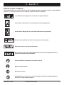
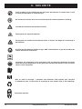
PRODUCT SAFETY SYMBOLS
The symbols below are used on the lift system to identify warnings, mandatory actions, and prohibited
actions. It is very important for you to read and understand them completely.
Crush Hazard—Moving parts can crush and cut. Keep hands clear.
Crush Hazard—Moving lift can crush. Keep feet clear during operation
Crush Hazard—Moving lift can crush. Keep hands clear during operation.
Do not sit on Power Chair or
Scooter while activating lift
or during transport.
Do not sit on mobility device while activating lift or during transport.
Keep area clean, dry, and free of obstructions.
Do not remove cover! Only authorized personnel may service this equipment. Refer to
manual for important safety information.
Read and follow the information in the owner’s manual.
Maximum lifting capacity.
Do not use as a step.
Avoid exposure to rain, snow, ice, salt, or standing water whenever possible. Maintain
and store in a clean and dry condition.

6 www.pridemobility.com Backpacker Series
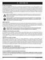
II. SAFETY
Keep tools and other metal objects away from battery terminals. Contact with tools can
cause electrical shock.
Do not allow unsupervised children to play near the lift while the battery is charging.
Corrosive chemicals contained in battery.
Explosive conditions exist!
Pinch/Crush points created during assembly and/or operation. Keep hands/fingers away from
moving components during operation.
Use only AGM or Gel-Cell batteries to reduce the risk of leakage or explosive conditions.
Battery posts, terminals and related accessories contain lead and lead compounds. Wear
goggles and gloves when handling batteries and wash hands after handling.
Disposal and recycling – Contact your authorized Pride Provider for information on proper
disposal of your Pride product and its packaging
Manual Override

Backpacker Series www.pridemobility.com 7
II. SAFETY
Remove transit screw and washer prior to operating the lift for the first time.

8 www.pridemobility.com Backpacker Series
II. SAFETY
LIFTING CAPABILITIES
The Backpacker Lift System is designed for a maximum lifting capacity of 350 lbs. (159 kg). Under no
circumstances should the Backpacker Lift System be made to exceed this weight limit. Subjecting the
lift system to the strain of lifting more that it is designed to may cause it to fail, resulting in damage to
the mobility product and/or injury to the lift operator. Refer to the mobility device owner’s manual for
information on the overall weight of the mobility product before lifting.
WARNING! Exceeding the maximum lift capacity of 350 lbs. (159 kg) may cause the lift system to fail,
resulting in damage to the mobility product and/or injury to the lift operator.
WARNING! Adding accessories, oversize batteries, or a different seat will increase the weight of
your mobility product. Verify with your authorized Pride Provider the total weight of your mobility
device, including additions.
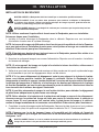
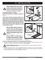
INSTALLATION
Your Backpacker Lift System is an interior lift designed for installation into various brands of SUVs and
full-sized/mini vans. Read and fully understand the installation instructions provided in this manual and
related literature for your brand of vehicle before installing the lift system.
WARNING! Before drilling or cutting into the vehicle, make absolutely certain through visual
inspection that there are no obstructions, such as the fuel tank, exhaust pipes, or electrical wires,
in the path of the drill bit.
LIFTING NON-PRIDE PRODUCTS
The Backpacker Lift System is an extremely versatile device, which users may employ to lift items other
than Pride products. Pride has no control over such use, nor can Pride anticipate every possible use
to which a Backpacker Lift System may be put. Operating the lift system outside of the safe limits as
discussed in this manual or using the lift system to lift any item deemed by Pride to be incompatible
with the lift system is done at the operator’s own risk, and Pride accepts no liability for damage or injury
resulting from such use.
PRE-LIFT INSPECTION
Before operating the Backpacker Lift System, conduct a careful survey of your surroundings to ensure
that the lift system has a clear path of operation. Remove any possible obstructions before operating
the lift and do not allow children to operate or play near the lift. Ensure that all parts of the lift system are
completely fastened before loading the mobility device onto the lift platform, and make sure the mobility
device is properly secured before operating the lift system.
OPERATOR POSITIONING
The operator of the lift should stand a safe distance from the unit being lifted/lowered to ensure that his/
her feet are never positioned under the raised lift platform. The operator should also keep his/her hands
clear of the lift system during operation.
TRANSPORT VEHICLE POSITIONING
Be sure your vehicle is parked on flat, level ground before attempting to load, lift, or remove a mobility
device with the Backpacker Lift System. Make sure the vehicle emergency park brake is engaged
before loading or unloading a mobility device.

Backpacker Series www.pridemobility.com 9
III. INSTALLATION
BACKPACKER LIFT SYSTEM INSTALLATION
WARNING! The Backpacker Lift System should be installed by an authorized service technician only.
WARNING! At least two people should lift the Backpacker into the rear of the vehicle. Use proper
lifting techniques and avoid lifting beyond your physical capability.
WARNING! Avoid pinch points! Do not hold the lift frame by the pivot points when installing the
Backpacker.
NOTE: Use only the supplied hardware to install the Backpacker Lift System.
Follow these steps for installation:
1. Install the Backpacker securement system to the vehicle. Refer to the installation instructions
supplied with the securement system.
NOTE: Securement systems vary depending on vehicle manufacturer. Pride recommends use of
only the securement system provided with the lift and that you follow any instructions provided
by the manufacturer for installation.
NOTE: If your Backpacker is equipped with caps, the caps can be removed if additional clearance
is needed.
2. Connect the lift system to a power source. See “Wiring Harness Installation.”
NOTE: The lift system is equipped with an optional onboard battery, refer to “Onboard Battery
Installation.”
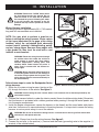
3. Ensure that all mounting hardware is fully tightened once the lift has been centered and all required
clearances have been achieved.
NOTE: If there is not adequate clearance between the bumper and the platform frame, you may
need to install an end support bracket. Remove the Backpacker from the van and install the end
support bracket close to the rear door opening. Reinstall the lift into the vehicle, making sure
that the bolts protruding from the bottom plate of the Backpacker closest to the vehicle door
snap into the tapped holes on the top of the end support bracket.
NOTE: It may be required to trim the rear inside sill to achieve the adequate platform clearance
with the platform under load.
NOTE: Pay attention to the path of the lift platform during operation. Make sure the lift does
not rub against or interfere with the vehicle in any way. If you notice any contact between the
lift platform and the vehicle, stop lift operation immediately and contact your authorized Pride
Provider for assistance.
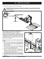
4. Run the Backpacker through an entire lift cycle. Lower the platform to the ground and raise the
platform to the fully stowed position in the vehicle. See IV. “Operation.”
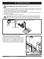
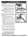
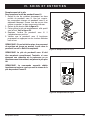
NOTE: Ensure the yellow transit screw and washer have been removed from the front of the lift
and the rubber bushing has been installed before operation. See figures 1 and 2.
WARNING! Remove the transit screw and washer prior to lift operation. Failure to do so may result
in serious equipment damage.

10 www.pridemobility.com Backpacker Series
III. INSTALLATION
Figure 1. Transit Screw Removal
WARNING! Release the “DOWN” button when
the lift platform touches the ground. Do not
allow the motor to run after the lift platform
has touched the ground. Allowing the motor
to run will increase the pressure on the lift
platform and may result in product or vehicle
damage.
Wiring Harness Installation
The wiring harness is approximately 25 ft. (7.62 meters)
long and will accommodate most vehicles.
NOTE: You may wish to perform a practice run
before installing the wiring harness. Route a piece
of light rope (equivalent to the gage of the wiring
harness) along the anticipated path observing
contact points, potential rubbing/chafing points,
and any sharp edges. Remove sharp edges with
a fine grade file, then treat the steel with a rust
inhibitor or metal sealant.
WARNING! Route the wiring harness through
the vehicle rather than under the vehicle to
avoid coming in contact with sharp edges,
extreme temperatures, moving parts, and
roadway debris. Power shorts may occur if
wires come in contact with hot exhaust or
sharp edges.
WARNING! Never attach the wiring harness to
a secondary power source. Do not attempt to
use trailer wiring to power the lift system. The
wiring harness must be connected directly to
the vehicle battery.
Follow these steps to route the Backpacker Series
wiring harness:
1. Route the lift system wiring harness (starting at the
lift) through the interior of the vehicle. See figure 3.
TRANSIT SCREW
WASHER
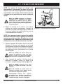
Figure 2. Rubber Bushing Location/Installation
WARNING! Avoid routing the wire harness where it will interfere with or become pinched by the
securement system.
2. Conceal the harness behind or under the interior panels (there should be existing holes). Be certain
that the harness is protected with a rubber grommet when passing it through the metal panels and
into the engine compartment.
3. Inside the engine compartment, secure the harness to the firewall and the inner fender with plastic
wire tires. Use care not to cause abrasions to the wiring harness. It is important to secure the wiring
harness at various points along its run of the vehicle.
WARNING! Do not cut or shorten the wiring harness. If the harness is too long, coil the excess wire
and secure it with plastic wire ties.
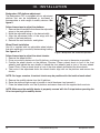
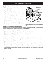
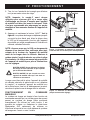
4. Remove the 15-amp fuse from the wiring harness. See figure 3.
5. Connect the red wire to the positive (+) terminal and the black (grounding) wire to the negative (-)
terminal of the vehicle battery.
RUBBER BUSHING
RUBBER BUSHING

Backpacker Series www.pridemobility.com 11
III. INSTALLATION
LIFT WIRING
CONNECTION
Figure 3. Wiring Harness Installation - Backpacker Plus
VEHICLE BATTERY
GROUNDING WIRE
FUSE
HAND CONTROL
6. Reinstall the 15-amp fuse to the wiring harness.
WARNING! Before operating the lift, inspect the wiring harness for proper routing and grounding.
Improper routing can cause damage to the harness, and improper grounding can cause damage to
the electrical system.
Optional onboard battery pack installation
The optional onboard battery is designed for easy
installation as it does not require wires to be routed
through or under the vehicle. If using the optional TYPE
II onboard battery pack, please refer to the manual
supplied with the pack for proper operating instructions
and harness connections.
Follow these steps to install the onboard battery
(Type I)
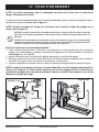
1. Remove the nuts and washers from the protruding
bolts on the side of the lift motor housing. See figure 4.
2. Slide the spacer bar onto the protruding bolts, if not
already installed.
3. Mount the battery case onto the protruding bolts
and secure into position with the nuts and rubber
caps removed earlier. See figure 4.
4. Insert the onboard battery into the battery case,
making sure that the connector on the bottom of
the battery aligns and fully connects with the mating
connector inside the battery case.
5. Connect the male connector on the battery cable to
the female connector at the base of the Backpacker.
6. Secure the battery cable to the other cables with
wire ties.
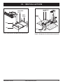
Figure 4. Onboard Battery installation (Type I)
NUTS
SPACER BAR

12 www.pridemobility.com Backpacker Series
III. INSTALLATION
Follow these steps to adjust the wheel chocks:
1. Remove the wheel chocks.
2. Drive your mobility device onto the lift platform, positioning it as near to the center as possible.
3. Position the wheel chocks on the platform. Scooters: Place a wheel chock in front of the front
wheel(s) and behind the rear wheels or behind the front wheel(s) and in front of the rear wheels.
Power Chairs: Place a wheel chock in front of the drive wheels and behind the drive wheels.
4. Take note of the adjustment holes the wheel chocks align with on the platform and remove the
chocks.
NOTE: For larger scooters, the wheel chocks may be positioned to the inside of each wheel.
5. Remove the mobility device from the lift platform.
6. Raise the platform high enough to be able to install hardware from beneath it.
7. Place the wheel chocks onto the lift platform and secure them with the supplied bolts and nuts.
NOTE: Make sure the mobility device is properly secured with the Y-strap before operating the
lift or transporting the mobility device.
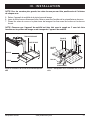
ALIGN PLATFORM
HOLES TO DESIRED
WIDTH
Figure 5. Backpacker AVP Platform Adjustment
ADJUSTABLE
WING
BOLT
NUT
BOLT
NUT
Backpacker AVP platform adjustment
The Backpacker AVP is equipped with an adjustment
platform that can be lengthened or shortened to
accommodate a wide range of mobility devices. See
figure 5.
Follow these steps to adjust the platform:
1. Remove the nuts and bolts that secure the adjustable
wings to the main platform.
2. Move the adjustable wings to the desired width.
3. Align the adjustment holes of the wings with the
holes of the main platform.
4. Reinstall the nuts and bolts, and tighten.
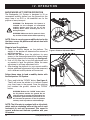
Wheel Chock Installation
Your lift is supplied with two adjustable wheel chocks
that aid in centering your mobility device during loading.
See figure 6 or 7.

Backpacker Series www.pridemobility.com 13
III. INSTALLATION
Figure 6. Backpacker AVP Wheel Chock Installation
Figure 7. Backpacker Plus Wheel Chock Installation
ADJUSTABLE
HOLES
WHEEL
CHOCK
BOLT
NUT
ADJUSTABLE
HOLES
WHEEL
CHOCK
BOLT
SPACER
BAR

14 www.pridemobility.com Backpacker Series
IV. OPERATION
BACKPACKER LIFT SYSTEM OPERATION
The Backpacker Lift System is designed to lift an
unoccupied mobility device from the ground into the
cargo area of an SUV or full-sized/mini van for the
purpose of easy transport.
WARNING! The Backpacker Lift System is
intended for the transport of unoccupied
mobility devices only. Do not sit on the
mobility device while activating the lift or
during transport.
WARNING! Make sure the lift system is clean,
dry, and free of obstructions before operating.
NOTE: Prior to carrying your mobility device for the
first time, ensure the platform will remain level with
the device on it.
Steps to level the platform:
1. Place the mobility device on the platform. The
weight of the device will determine the amount of
adjusting needed.
2. Remove the device from the platform for easy
access to the three adjustment bolts located where
the platform connects to the lowering arm. See figure 8.
3. Use a 3/16 Allen key to turn the adjustment bolts
as needed to level the platform. Make the same
adjustment to all three adjustment bolts.
4. After leveling the platform for your current mobility
device, additional adjustments will not be necessary
until a different mobility device will be carried.
Follow these steps to load a mobility device with
the Backpacker Lift System.
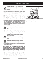
1. Press and hold the “DOWN” button. See figure 9.
The lift will move the vehicle to its farthest forward
stop, then lower to the ground. Once the platform
has reached the ground, release the “DOWN”
button.
WARNING! Release the “DOWN” button when
the lift platform touches the ground. Do not
allow the motor to run after the lift platform has
touched the ground. Allowing the motor to run
will increase the pressure on the lift platform
and may result in product or vehicle damage.
NOTE: The lift motor is equipped with a slip clutch,
which emits a ratcheting noise at the end of each
horizontal (in and out) movement. This sound is
normal and does not indicate a problem with your
lift system.
Figure 8. Platform Adjustment Bolts
Figure 9. Hand Control

Backpacker Series www.pridemobility.com 15
IV. OPERATION
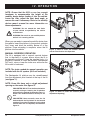
Figure 10. Y–strap Positioning
WARNING! Maintain a safe distance from
the lift platform. Ensure your feet are not
positioned under the lift platform and keep
your hands clear of the lift system during
operation.
2. Set the speed control to the slowest setting and
carefully drive the mobility device onto the lift
platform, being sure to center the mobility device
between the previously installed wheel chocks.
NOTE: You may wish to load the mobility device
while standing next to it using the manual freewheel
feature. Refer to the mobility device owner’s manual
for more information on manual freewheel mode.
3. Shut down the power to the mobility device, remove
the key if applicable, and make sure the unit is in
drive mode (drive motors engaged). Refer to the
mobility device owner’s manual for more information
on drive mode.
WARNING! Never leave a mobility device in
freewheel mode during lift system transport,
as the mobility device could roll or shift on its
own.
4. Secure the mobility device to the platform by draping
the Y-strap over the seat and buckling the strap
securely. See figure 10.
WARNING! Ensure the area behind the lift is
clear of obstructions.
WARNING! Never attempt to secure the Y-strap
over the seat back or armrests of the mobility
device.
MANDATORY! Always secure the mobility
device to the lift with the Y-strap before lift
system operation or vehicle transport.
5. Pull the end of the strap tightly to remove any excess
slack over the seat.
NOTE: Inspect the Y-strap before each use to
ensure there are no signs of fraying or wear.
Ensure that the mobility device is secured properly
before transport. Pride is not liable for damage or
loss resulting from improper securing of a mobility
device.
6. Press and hold the “UP” button. See figure 9. The
lift will move up to its highest lift point, then slide into
the SUV or van. Once the mobility device is stowed
completely within the vehicle, release the button.

16 www.pridemobility.com Backpacker Series
IV. OPERATION
NOTE: Ensure that the SUV or van has enough
headroom to accommodate the height of the
mobility device before loading it into the vehicle.
Lower the tiller, adjust the seat back angle, or
remove the seat if necessary. Refer to the mobility
device owner’s manual for more information on
these adjustments.
WARNING! Do not exceed the load limits
of your vehicle as specified by the vehicle
manufacturer.
WARNING! Do not sit on your mobility device
while it is in a moving vehicle.
When you are ready to remove the mobility device from
the vehicle, lower the platform to the ground, unfasten
the Y-strap, and drive the mobility device off of the
platform. Once unloading is complete, return the lift
platform into the vehicle.
MANUAL OVERRIDE OPERATION
The lift is equipped with a manual override feature
that, in the event of a power failure, allows the lift to
be manually positioned. Using the supplied tools, it is
possible to elevate or lower the platform (Backpacker
AVP only), raise or lower the tower arm, and move the
lift forward or backward.
NOTE: The tools needed for manual operation are
included with the lift system. (Drill not included.)
The Backpacker lift platform can be raised/lowered
from the adjustment point located at the top of the lift
(see figure 11).
NOTE: Some lifts have only a single adjustment
opening on the motor. See figure 12.
PROHIBITED! DO NOT use the flex-shaft when
manually raising or lowering the lift platform
while using the method illustrated in figure 11.
Attach the needed hardware directly to the
drill.
PROHIBITED! Never manually move the lift
backward with the lift platform in the lowered
position. Ensure the lift platform is fully raised
and
the tower arm is completely retracted. See
figure 14.
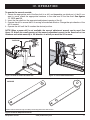
Figure 11. Raise or Lower the Platform. DO NOT
use the Flex-Shaft for this Operation
Figure 12. Raise or Lower the Platform (Single
Adjustment Opening)
HARDWARE
LIFT PLATFORM
CAPS

Backpacker Series www.pridemobility.com 17
IV. OPERATION
To operate the manual override:
1. Secure the appropriate end of the flex-shaft to a drill, and depending on which part of the lift you
want to move, attach the appropriate hardware to the other end of the flex-shaft. See figures
11, 12 13, and 14.
2. Insert the flex-shaft into the appropriate adjustment opening of the lift.
3. Operate the drill to ensure the lift is moving in the desired direction. Change the spin direction of the
drill if needed.
4. Operate the drill until the lift reaches the desired position.
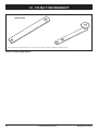
NOTE: When a power drill is not available, the manual adjustment wrench can be used. See
figure 15. Attach the small opening of the manual adjustment wrench to the flex-shaft or hex
hardware and rotate manually in the direction in which you want the lift to move.
Figure 13. Raise or Lower the Tower Arm Figure 14. Front-to-Back Movement
Figure 15. Manual Adjustment Wrench
HARDWARE
TOWER ARM
HARDWARE
*Either of the two wrenches may come with your lift. They perform the same function.
HARDWARE

18 www.pridemobility.com Backpacker Series
IV. OPERATION
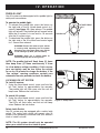
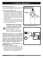
PUDDLE LIGHT
Your lift system may be equipped with a puddle light for
safety and convenience.
To operate the puddle light:
1. To activate the puddle light, press the button on
the right side of the lift system hand control for 1
second (see figure 16), then release. The puddle
light will activate. The puddle light will remain active
while the lift system is in use and for 10 seconds
after the lift system stops.
2. To deactivate the puddle light, press the button on
the right side of the lift system hand control again
for 1 second then release.
WARNING! Ensure the motor of your vehicle
is running while operating the lift system.
Operating your lift system when your vehicle
is not running may drain your car battery.
WARNING! Never run a vehicle inside an
enclosure/garage due to toxic gasses.
NOTE: The puddle light will flash three (3) times
then beep three (3) times continuously if there
is a low battery voltage condition. If this occurs,
your car battery may be low. Allow the vehicle
to run for 15 minutes to charge the battery. If the
“low voltage” warning continues, contact your
automotive service provider to check the battery.
LOCK/UNLOCK LIFT SYSTEM
To Lock lift system:
1. Using the wired hand control, press and hold the
left “lock” button for approximately five seconds.
The puddle light will flash once, and the unit will
beep once. Release the lock button.
To unlock lift system:
1. Using the wired hand control, press and hold the
left “lock” button for approximately five seconds.
The LEDs will flash twice, and the unit will beep
twice. Release the lock button.
Safety Latch Switch
Your lift system may be equipped with a safety latch
switch. The safety latch switch will prevent your lift
system from operating in the event that your vehicle’s
trunk or hatch is closed.
NOTE: The lift system should only be operated
when your vehicle’s trunk or hatch is open.
Figure 16. Hand Control
Figure 17. Safety Latch
ACTIVATE PUDDLE
LIGHT
LOCK/UNLOCK

Backpacker Series www.pridemobility.com 19
IV. OPERATION
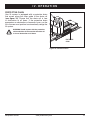
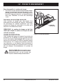
PROTECTIVE CHAIN
Your lift system is equipped with a protective chain
that moves along the outer guide of the chain rail
(see figure 18). Ensure that the chain rail is free
of obstruction at all times. If the protective chain
encounters an obstruction or becomes loose, run the
lift to the rear-most position to automatically realign the
lift system.
WARNING! Avoid contact with the protective
chain and chain rail. Ensure that the chain rail
is free of obstruction at all times.
Figure 18. Protective Chain
PROTECTIVE
CHAIN

20 www.pridemobility.com Backpacker Series
TROUBLESHOOTING
Any electromechanical device occasionally requires some troubleshooting. However, most of the
problems that may arise can usually be solved with a bit of thought and common sense. Many of these
problems occur because the battery is not fully charged or because the battery is worn down and can
no longer hold a charge.
What if the motor on my lift system will not operate?
■ Make sure the onboard battery or vehicle battery is fully charged.
■ Make sure all connections to the motor and battery are secure.
■ Check the wiring harness for signs of wear and decay. Replace the harness if necessary.
What if the lift system operates slowly up and or down?
■ Make sure the onboard battery or vehicle battery is fully charged.
■ Make sure all connections to the motor and battery are secure.
■ Check the wiring harness for signs of wear or decay. Replace the harness if necessary. Please see
the provider.
What if the lift platform does not lower completely to the ground?
Check to make sure that area under the lift platform is free of obstructions.
What if my wireless pendant will not operate?
■ Make sure that your vehicle’s hatch is fully open. If the safety hatch switch is activated, your lift
system will not operate.
■ Ensure that the wireless pendant is programmed to work with your lift system. This supplemental
information is provided with the Wireless Pendant. See “Programming the Wireless Pendant.”
■ If the hand control is fully operational but the wireless pendant does not work, the battery may need
to be changed. See “Battery Replacement.”
What if my lift system stops working?
■ Make sure the onboard battery or vehicle battery is fully charged.
■ Make sure all connections to the motor and battery are secure.
■ Check the wiring harness for signs of wear and decay. Contact your authorized Pride provider to
replace the harness if necessary.
■ Ensure that the wireless pendant is properly programmed to the lift system. Reset the circuit board
and reprogram the wireless pendant. This supplemental information is provided with the Wireless
Pendant. See “Programming the Wireless Pendant.”
NOTE: The puddle light will flash three (3) times then beep three (3) times continuously if there
is a low battery voltage condition. If this occurs, your car battery may be low. Contact your
automotive service provider to check or replace the battery.
V. TROUBLESHOOTING
La page charge ...
La page charge ...
La page charge ...
La page charge ...
La page charge ...
La page charge ...
La page charge ...
La page charge ...
La page charge ...
La page charge ...
La page charge ...
La page charge ...
La page charge ...
La page charge ...
La page charge ...
La page charge ...
La page charge ...
La page charge ...
La page charge ...
La page charge ...
La page charge ...
La page charge ...
La page charge ...
La page charge ...
La page charge ...
La page charge ...
La page charge ...
La page charge ...
La page charge ...
La page charge ...
La page charge ...
La page charge ...
-
 1
1
-
 2
2
-
 3
3
-
 4
4
-
 5
5
-
 6
6
-
 7
7
-
 8
8
-
 9
9
-
 10
10
-
 11
11
-
 12
12
-
 13
13
-
 14
14
-
 15
15
-
 16
16
-
 17
17
-
 18
18
-
 19
19
-
 20
20
-
 21
21
-
 22
22
-
 23
23
-
 24
24
-
 25
25
-
 26
26
-
 27
27
-
 28
28
-
 29
29
-
 30
30
-
 31
31
-
 32
32
-
 33
33
-
 34
34
-
 35
35
-
 36
36
-
 37
37
-
 38
38
-
 39
39
-
 40
40
-
 41
41
-
 42
42
-
 43
43
-
 44
44
-
 45
45
-
 46
46
-
 47
47
-
 48
48
-
 49
49
-
 50
50
-
 51
51
-
 52
52


Pride Backpacker AVP 2.0 Le manuel du propriétaire
- Taper
- Le manuel du propriétaire
- Ce manuel convient également à
dans d''autres langues
Documents connexes
-
Pride Outlander Series Le manuel du propriétaire
-
-
-
Pride Go-Go Elite Traveller Le manuel du propriétaire
-
-
-

