3com Baseline Switch 2816 3CBLUG16 Manuel utilisateur
- Catégorie
- Commutateurs réseau
- Taper
- Manuel utilisateur
Ce manuel convient également à

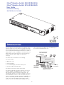
The 3Com Baseline Switch 2824 and the 3Com Baseline Switch
2816 are versatile, easy-to-use switches. It is ideal for users who
want the high-speed performance of 10/100/1000 switching but
do not need sophisticated management functions. The Switch is
shipped ready for use. No configuration is necessary. Your 3Com
Baseline Switch incorporates the latest in Green technology to
yield more than 25% power savings over the previous
technology.
The Switch can be rack-mounted or free standing.
Your Switch includes:
One power cord
Rack mounting kit
Four standard height, self-adhesive rubber pads
This User Guide and warranty card
The Switch is powered from the AC mains supply.
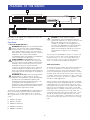
The Switch provides high performance switched connections to
10 Mbps, 100 Mbps, and 1000 Mbps hubs, switches, servers
and workstations that need a dedicated switched link. The
following figure illustrates one possible configuration. Each port
has a shielded RJ-45 connector on the front panel. Each port is
capable of operating at 10 Mbps, 100 Mbps or 1000 Mbps. The
ports can automatically determine the speed and the duplex
mode of the connected equipment and provides a suitable
switched connection. At 10 Mbps and at 100 Mbps, the ports
can operate in half or full duplex mode. At 1000 Mbps, the
ports operate in full duplex mode only.
INTRODUCTION
Servers with
1000Mbps
connections
Dual Speed Switch
with 10/100 Mbps
connection
1000Mbps
connections
10/100Mbps Switch with
Gigabit Connection
Switch 2824
1
Link/Activity :Green
=
1
000M, Yellow
=
1
0/100M,
F
lash
=
Activity
Baseline Switch2824
3CBLUG24
10/100 /1000 Status
3Com
®
Baseline Switch 2824 (3CBLUG16)
3Com
®
Baseline Switch 2816 (3CBLUG24)
User Guide
Installationsanleitung
10017053 Rev AA Oct 2008

The numbers in this diagram refer to numbered sections in the
text. A 24-port unit is shown.
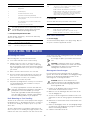
Front Panel
1 24 RJ-45 10/100/1000 Ports
WARNING
: RJ-45 ports. These are shielded RJ-45 data
sockets. They cannot be used as standard traditional
telephone sockets, or to connect the unit to a traditional
PBX or public telephone network. Only connect RJ-45
data connectors, network telephony systems, or network
telephones to these sockets. Either shielded or
unshielded data cables with shielded or unshielded jacks
can be connected to these data sockets.
AVERTISSEMENT: Les ports RJ-45. Ceux-ci sont
protégés par des prises de données. Ils ne peuvent pas
être utilisés comme prises de téléphone conventionnelles
standard, ni pour la connection de l’unité à un réseau
téléphonique central privé ou public. Raccorder
seulement connecteurs de données RJ-45, systèmes de
réseaux de téléphonie ou téléphones de réseaux à ces
prises. Il est possible de raccorder des câbles protégés ou
non protégés avec des jacks protégés ou non protégés à
ces prises de don.
WARNUNG: RJ-45-Porte. Diese Porte sind geschützte
Datensteckdosen. Sie dürfen weder wie normale
traditionelle Telefonsteckdosen noch für die Verbindung
der Einheit mit einem traditionellem privatem oder
öffentlichem Telefonnetzwerk gebraucht werden. Nur
RJ-45-Datenanscluße, Telefonnetzsysteme or
Netztelefone an diese Steckdosen anschließen. Entweder
geschützte oder ungeschützte Buchsen dürfen an diese
Datensteckdosen angeschlossen werden.
The Switch has 24/16 10/100/1000 Mbps auto-negotiating ports.
Each port automatically negotiates with the attached device to
determine the correct speed and duplex mode of operation.
Once negotiated, the port will operate in one of the following
modes:
10BASE-T half duplex
10BASE-T full duplex
100BASE-TX half duplex
100BASE-TX full duplex
1000BASE-T full duplex
CAUTION: The Switch supports full duplex
auto-negotiation. If the connected device does not
support auto-negotiation, the Switch will operate in half
duplex mode, and therefore can only operate at
10 Mbps or 100 Mbps. In such a configuration, you
may notice some degradation of network performance.
3Com recommends that you use devices that are
capable of auto-negotiation (and that you ensure that
auto-negotiation is enabled, if it is a configurable
option).
All ports auto-sense an MDI/MDIX connection so each port can
be connected to a device with a normal ‘straight through’ TP
(twisted pair) cable or a ‘cross-over’ TP cable. Any port can
therefore be used to connect to either another switch port,
server, or workstation without additional configuration.
Traffic Prioritization
The Switch offers priority queuing, which means all packets that
are received are examined to see if they have been priority
encoded. When a packet is received, the Switch will read the
priority level and determine the appropriate channel to forward
the packet based on the priority level. This feature can be useful,
for example, during excessive loads when one type of traffic may
require priority over another. The Switch is configured to comply
with 802.1p, VLAN tagged frames.
Traffic prioritization ensures that high priority data is forwarded
through the Switch without being delayed by lower priority data.
It differentiates traffic into classes and prioritizes those classes
automatically. Traffic prioritization uses the multiple traffic queues
that are present in the hardware of the Switch to ensure that
high priority traffic is forwarded on a different queue from lower
priority traffic, and is given preference over that traffic. This
ensures that time-sensitive traffic gets the highest level of service.
The 802.1D standard specifies eight distinct levels of priority
(0 to 7), each of which relates to a particular type of traffic. The
priority levels and their traffic types are shown in the following
table.
FEATURES OF THE SWITCH
4
2
3
1
1
13
4
16
5
17
8
9
20
21
Baseline Switch 2824
3CBLUG24
12
24
Link/Activity : Green = 1000M, Yellow = 10/100M,Flash =Activity
10 / 100 / 1000 Status
Baseline Switch 2824
3CBLUG24
!
2

The traffic prioritization feature supported by the Switch
is compatible with the relevant sections of the IEEE
802.1D standard (incorporating IEEE 802.1p).
2 Activity/Link/Speed Status LEDs
The LED, labelled “Link/Activity,” shows the link and activity
status of the related ports:
3
Power LED
The Power LED shows the power status of the Switch:
Rear Panel Connections
4 Power Supply
The Switch automatically adjusts to the supply voltage. Only use
the power cord that is supplied with the unit.
Positioning the Switch
When deciding where to position the Switch ensure:
It is accessible and cables can be connected easily.
Cabling is away from sources of electrical noise. These
include lift shafts, microwave ovens, and air conditioning
units. Electromagnetic fields can interfere with the signals on
copper cabling and introduce errors, therefore slowing down
your network.
Water or moisture cannot enter the case of the unit.
Air flow around the unit and through the vents in the side
of the case is not restricted (3Com recommends that you
provide a minimum of 25 mm (1 in.) clearance).
The air is as free from dust as possible.
Temperature operating limits are not likely to be exceeded. It
is recommended that the unit is installed in a clean, air
conditioned environment.
It is always a good practice to wear an anti-static wrist
strap when installing network equipment, connected to a
ground point. If one is not available, try to keep in
contact with a grounded rack and avoid touching the
unit's ports and connectors, if possible. Static discharge
can cause reliability problems in your equipment.
Rack Mounting or Free Standing
This unit can be mounted in a 19-inch equipment rack using the
Mounting Kit. Refer to “Mounting Kit Instructions” on page 4. It
can also be free standing. Do not place objects on top of the
unit or stack.
The unit is supplied with four self-adhesive rubber pads. If the
unit is to be part of a free standing stack, apply the pads to each
marked corner area on the underside of the unit. Place the unit
on top of the lower unit, ensuring that the pads locate with the
recesses of the lower unit.
Do not apply the pads if you intend to rack mount the
unit.
CAUTION: If installing the Switch in a free standing
stack of different sized units, the smaller units must be
installed above the larger ones. Do not build a free
standing stack of more than six units.
Montagesatz Anweisungen
Der Switch wird mit zwei Halterungen und vier Schrauben
geliefert. Diese werde für den Einbau in einen Baugruppenträger
benutzt. Bei der Montage der Baugruppe beachten Sie die
Anweisungen aus “Positioning the Switch”.
ACHTUNG: Entfernen Sie alle Kabel, bevor Sie
fortfahren. Entfernen Sie die selbstklebenden Polster
(Füße) von der Unterseite der Baugruppe, falls diese
bereits angebracht sind.
1 Plazieren Sie die Baugruppe aufrecht auf einer harten,
ebenen Fläche mit der Vorderseite zu Ihnen.
2 Ordnen Sie eine der Halterungen über den Löchern an der
Seite der Baugruppe an.
3 Stecken Sie zwei der mitgelieferten Schrauben in die Löcher
und drehen Sie diese mit einem geeigneten Schraubendreher
fest.
4 Widerholen Sie letzten beiden Schritte auf der anderen Seite
der Baugruppe.
5 Führen Sie die Baugruppe in den 19" (Zoll) Baugruppenträger
ein und sichern sie die Baugruppe mit geeigneten Schrauben.
(Nicht im Lieferumfang enthalten).
6 Schließen Sie alle Kabel wieder an.
Priority Level Traffic Type
0 Best Effort
1 Background
2 Standard (spare)
3 Excellent Effort (business critical)
4 Controlled Load (streaming multimedia)
5 Video (Interactive media), less than 100 milliseconds
latency and jitter.
6 Voice (Interactive voice), less than 10 milliseconds
latency and jitter.
7 Network Control Reserved traffic
Status Meaning
Green The link is operating at 1000 Mbps.
Yellow The link is operating at 10 or 100 Mbps.
Flashing Packets are being received or transmitted on the port.
Off The link has not been established, either nothing is connected
to the port, or there is a problem:
■ Check that the attached device is powered on.
■ Check that the cable is the correct type and is not faulty.
If these checks do not identify the cause of the problem, it
may be that the unit or the device connected to the port is
faulty. Contact your supplier for further advice.
Status Meaning
Green The unit is powered on and ready for use.
Off ■ The unit is not receiving power:
■ Check that the power cord is connected correctly.
■ If the unit still does not operate, contact your supplier.
INSTALLING THE SWITCH
!
!
3

Connecting to a Network Device
Follow these guidelines to connect a device to the Switch:
Use Category 5 unshielded or shielded (screened) 100 Ohm
TP cable (or Category 3 cable for a 10 Mbps connection).
3Com recommends using Category 5E cable for 1000BASE-T
operation.
The maximum length of cable for each connection is
100 m (328 ft).
Connect one end of the cable to an RJ-45 port on the
Switch, and the other end to the appropriate RJ-45 port on
the connecting device.
Power Supply
Power problems can be the cause of serious failures and
downtime in your network. Ensure that the power input to your
system is clean and free from sags and surges to avoid
unforeseen network outages. 3Com recommends that you install
power conditioning, especially in areas prone to black outs,
power dips and electrical storms.
Powering Up
Use the following sequence to power up the Switch:
1 Check the network connections and cables.
2 Connect the power supply cable to the appropriate power
socket located on the rear panel of the unit.
3 Connect the plug to the power supply outlet socket and
switch on the power supply at the socket.
When the switch is powered on, the Power LED lights green. If it
does not, see reference 4 in “Features of the Switch” on page 3.
Introduction
The Switch is supplied with two mounting brackets and four
screws. These are used for rack mounting the unit. When
mounting the unit, you should take note of the guidelines given
in “Positioning the Switch” on page 3.
Rack Mounting the Units
The Switch is 1U high and will fit a standard 19-inch rack.
CAUTION: Disconnect all cables from the unit before
continuing. Remove the self-adhesive pads from the
underside of the unit, if already fitted.
1 Place the unit the right way up on a hard, flat surface with
the front facing towards you.
2 Locate a mounting bracket over the mounting holes on one
side of the unit (refer to the figure following step 6).
3 Insert the two screws supplied in the mounting kit and fully
tighten with a suitable screwdriver.
4 Repeat the two previous steps for the other side of the unit.
5 Insert the unit into the 19-inch rack and secure with suitable
screws (not provided).
6 Reconnect all cables.
At frequent intervals you should visually check the Switch.
Regular checks can give you an early warning of a possible
failure; any problems can then be attended to when there will be
least effect on users.
Check that all external cabling connections are secure and that
no cables are pulled taut.
Refer to the information about LEDs given earlier in this guide to
see if the problem can be identified and solved. Here are some
common problems that can occur:
Activity Status LED not lit for a port that has a connection.
There is a problem with this connection. Check that:
The device being connected to is powered on and operating
correctly.
The cable is connected at both ends.
You are using a TP cable that is not damaged.
If the connection is to a workstation, that the workstation’s
network interface card is installed and configured correctly.
All Activity LEDs appear to be lit continually. There may be
broadcast storms on the network. Remove port connections one
at a time, waiting a few seconds between each port. If the LEDs
go off after removing a port connection, the device that was
connected to that port is introducing an excessive amount of
broadcast frames to the network (some pieces of network
equipment operate by sending out broadcast frames regularly).
Refer to the documentation that accompanies the device for
information on disabling the broadcast operation.
If the problem persists and the unit still does not operate
successfully, contact your supplier with the following information
before returning the unit:
Product number and serial number (printed on a label
supplied with the unit)
A brief description of the fault condition
MOUNTING KIT INSTRUCTIONS
PROBLEM SOLVING
4

Please read the following safety information carefully
before installing the Switch.
WARNING: Installation and removal of the unit must be carried out by
qualified personnel only.
If installing Switch 2824/Switch 2816 in a stack with other 3Com Hub or
Switch units, larger units must be installed below the narrower Hub or
Switch units.
The unit must be connected to an earthed (grounded) outlet to comply with
international safety standards.
Do not connect the unit to an A.C. outlet (power supply) without an earth
(ground) connection.
The appliance coupler (the connector to the unit and not the wall plug)
must have a configuration for mating with an EN 60320/IEC 320 appliance
inlet.
The socket outlet must be near to the unit and easily accessible. You can
only remove power from the unit by disconnecting the power cord from the
outlet.
This unit operates under SELV (Safety Extra Low Voltage) conditions
according to IEC60950-1. The conditions are only maintained if the
equipment to which it is connected also operates under SELV conditions.
France and Peru only
This unit cannot be powered from IT
†
supplies. If your supplies are of IT type, this
unit must be powered by 230 V (2P+T) via an isolation transformer ratio 1:1, with
the secondary connection point labelled Neutral, connected directly to earth
(ground).
†
Impédance à la terre
Power Cord Set
This must be approved for the country where it will be used. e.g.
Veuillez lire à fond l'information de la sécurité suivante
avant d'installer le Switch.
AVERTISSEMENT: L’installation et la dépose de ce groupe doivent être
confiés à un personnel qualifié.
Si vous entassez l’unité Switch avec les unités SuperStack II Hub, l’unité
Switch doit être installée en dessous des unités Hub plus étroites.
Ne branchez pas votre appareil sur une prise secteur (alimentation
électrique) lorsqu'il n'y a pas de connexion de mise à la terre (mise à la
masse).
Vous devez raccorder ce groupe à une sortie mise à la terre (mise à la
masse) afin de respecter les normes internationales de sécurité.
Le coupleur d’appareil (le connecteur du groupe et non pas la prise murale)
doit respecter une configuration qui permet un branchement sur une entrée
d’appareil EN 60320/IEC 320.
La prise secteur doit se trouver à proximité de l’appareil et son accès doit
être facile. Vous ne pouvez mettre l’appareil hors circuit qu’en débranchant
son cordon électrique au niveau de cette prise.
L’appareil fonctionne à une tension extrêmement basse de sécurité qui est
conforme à la norme IEC60950-1. Ces conditions ne sont maintenues que si
l’équipement auquel il est raccordé fonctionne dans les mêmes conditions.
France et Pérou uniquement:
Ce groupe ne peut pas être alimenté par un dispositif à impédance à la terre. Si vos
alimentations sont du type impédance à la terre, ce groupe doit être alimenté par
une tension de 230 V (2 P+T) par le biais d’un transformateur d’isolement à rapport
1:1, avec un point secondaire de connexion portant l’appellation Neutre et avec
raccordement direct à la terre (masse).
Cordon électrique
Il doit être agréé dans le pays d’utilisation.
Bitte unbedingt vor dem Einbauen des Switches die
folgenden Sicherheitsanweisungen durchlesen.
WARNUNG: Die Installation und der Ausbau des Geräts darf nur durch
Fachpersonal erfolgen.
Wenn der Switch 2824/Switch 2816 mit anderen 3Com Hubs oder Switche
gestapelt werden soll, müssen grössere Geräte unter den schmaleren Hubs
eingebaut werden.
Das Gerät sollte nicht an eine ungeerdete Wechselstromsteckdose
angeschlossen werden.
Das Gerät muß an eine geerdete Steckdose angeschlossen werden, welche
die internationalen Sicherheitsnormen erfüllt.
Der Gerätestecker (der Anschluß an das Gerät, nicht der
Wandsteckdosenstecker) muß einen gemäß EN 60320/IEC 320
konfigurierten Geräteeingang haben.
Die Netzsteckdose muß in der Nähe des Geräts und leicht zugänglich sein.
Die Stromversorgung des Geräts kann nur durch Herausziehen des
Gerätenetzkabels aus der Netzsteckdose unterbrochen werden.
Der Betrieb dieses Geräts erfolgt unter den SELV-Bedingungen
(Sicherheitskleinstspannung) gemäß IEC60950-1. Diese Bedingungen sind
nur gegeben, wenn auch die an das Gerät angeschlossenen Geräte unter
SELV-Bedingungen betrieben werden.
SAFETY INFORMATION
U.S.A. and
Canada
■ The cord set must be UL-approved and CSA certified.
■ The minimum specifications for the flexible cord are:
No. 18 AWG
Type SV or SJ
3-conductor
■ The cord set must have a rated current capacity of at least
10 A.
■ The attachment plug must be an earth-grounding type with a
NEMA 5-15P (15 A, 125 V) or NEMA 6-15P (15 A, 250 V)
configuration.
Denmark
■ The supply plug must comply with Section 107-2-D1, Standard
DK2-1a or DK2-5a.
Switzerland
■ The supply plug must comply with SEV/ASE 1011.
UK
■ The supply plug must comply with BS1363 (3-pin 13-amp) and
be fitted with a 5 A fuse which complies with BS1362.
■ The mains cord must be <HAR> or <BASEC> marked and be
of type HO3VVF3GO.75 (minimum).
Europe
■ The supply plug must comply with CEE7/7 (“SCHUKO”)
■ The mains cord must be <HAR> or <BASEC> marked and be
of type HO3VVF3GO.75 (minimum).
L’INFORMATION DE SÉCURITÉ IMPORTANTE
Etats-Unis et
Canada:
■ Le cordon doit avoir reçu l’homologation des UL et un
certificat de la CSA.
■ Le cordon souple doit respecter, à titre minimum, les
spécifications suivantes:
calibre 18 AWG
type SV ou SJ
à 3 conducteurs
■ Le cordon doit être en mesure d’acheminer un courant
nominal d’au moins 10 A.
■ La prise femelle de branchement doit être du type à mise à la
terre (mise à la masse) et respecter la configuration NEMA
5-15P (15 A, 125 V) ou NEMA 6-15P (15 A, 250 V).
Danemark:
■ La prise mâle d’alimentation doit respecter la section 107-2 D1
de la norme DK2 1a ou DK2 5a.
Suisse:
■ La prise mâle d’alimentation doit respecter la norme SEV/ASE
1011.
Europe
■ La prise secteur doit être conforme aux normes CEE 7/7
(“SCHUKO”)
■ LE cordon secteur doit porter la mention <HAR> ou <BASEC>
et doit être de type HO3VVF3GO.75 (minimum).
WICHTIGE SICHERHEITSINFORMATIONEN
Stromkabel. Dies muss von dem Land, in dem es benutzt wird geprüft werden:
Schweiz
■ Dieser Stromstecker muß die SEV/ASE 1011Bestimmungen
einhalten.
Europe ■ Das Netzkabel muß vom Typ HO3VVF3GO.75
(Mindestanforderung) sein und die Aufschrift <HAR> oder
<BASEC> tragen.
■ Der Netzstecker muß die Norm CEE 7/7 erfüllen (”SCHUKO”).
5

Related Standards
The Switch has been designed to meet the following standards:
Environmental
Physical
Electrical
FCC Statement
This equipment has been tested and found to comply with the
limits for a Class A digital device, pursuant to part 15 of the FCC
rules. These limits are designed to provide reasonable protection
against harmful interference when the equipment is operated in
a commercial environment. This equipment generates, uses and
can radiate radio frequency energy and, if not installed and used
in accordance with the instructions, may cause harmful
interference to radio communications. Operation of this
equipment in a residential area is likely to cause harmful
interference to radio communications, in which case the user will
be required to correct the interference at their own expense.
Information To The User
If this equipment does cause interference to radio or television
reception, which can be determined by turning the equipment
off and on, the user is encouraged to try to correct the
interference by one or more of the following measures:
Reorient the receiving antenna
Relocate the equipment in relation to the receiver.
Move the equipment away from the receiver.
Plug the equipment into a different outlet so that equipment
and receiver are on different branch circuits.
If necessary, the user should consult the dealer or an experienced
radio/television technician for additional suggestions. The user
may find the following booklet prepared by the Federal
Communications Commission helpful:
How to Identify and Resolve Radio-TV Interference Problems
This booklet is available from the U.S. Government Printing
Office, Washington,
DC 20402, Stock No. 004-000-00345-4.
In order to meet FCC emissions limits, this equipment must be
used only with cables which comply with IEEE 802.3.
CE Statements (Europe)
EU Representative:
3Com Europe Limited
Peoplebuilding 2, Peoplebuilding Estate
Maylands Avenue
Hemel Hempstead, Hertfordshire
HP2 4NW
United Kingdom
This product complies with the European Low Voltage Directive
2006/95/EC and EMC Directive 2004/108/EC.
Warning: This is a Class A product. In a domestic
environment, this product may cause radio interference in
which case the user may be required to take adequate
measures.
A copy of the signed Declaration of Conformity can be
downloaded from the Product Support web page for the 3Com
Baseline Switch 28XX Product Family at http://www.3com.com.
Also available at
http://support.3com.com/doc/3CBLUGXX_EU_DOC.pdf
ICES Statement
This Class A digital apparatus complies with Canadian ICES-003.
Cet appareil numérique de la classe A est conforme a la norme
NMB-003 du Canada.
VCCI Statement
TECHNICAL INFORMATION
Functional ISO 8802-3, IEEE 802.3 (Ethernet), IEEE 802.3u (Fast
Ethernet), IEEE 802.3ab (Gigabit Ethernet), IEEE 802.3x
(Flow control on full duplex links), IEEE 802.3d
(Bridging), IEEE 802.1p (VLAN tagging/ priority queuing)
Safety UL 60950-1, IEC60950-1, CSA 22.2 #60950-1, IEC
60950-1
EMC Emissions EN 55022 Class A, FCC Part 15 Subpart B Class A,
ICES-003 Class A, VCCI Class A, AS/NZS CISPR 22
Class A
Immunity EN 55024
Operating
Temperature
0–40 °C (32–104 °F)
Humidity 10–95% (non-condensing)
Width 440 mm (17.3 in.)
Depth 173 mm (6.8 in.)
Height 43.6 mm (1.7 in.) or 1U
Weight Switch 2824: 1.65 kg (3.63 lb)
Switch 2816: 1.45 kg (3.19 lb)
Mounting Free standing, or 19-inch rack mounted using
the mounting kit supplied
Power Inlet IEC 320
AC Line Frequency 50/60 Hz
Input Voltage 100–240 VAC
Current Rating 1A
Maximum Power
Consumption
Switch 2824: 21.0W
Switch 2816: 14.7W
Maximum Power
Dissipation
Switch 2824: 71.7 BTU/hr
Switch 2816: 50.2 BTU/hr
REGULATORY NOTICES
6

3Com offers product registration, case management, and repair
services through eSupport.3com. You must have a user name
and password to access these services, which are described in
this appendix.
Register Your Product to Gain Service Benefits
To take advantage of warranty and other service benefits, you
must first register your product at:
http://eSupport.3com.com/. 3Com eSupport services are
based on accounts that are created or that you are authorized to
access.
Solve Problems Online
3Com offers the following support tool:
• 3Com Knowledgebase — Helps you to troubleshoot 3Com
products. This query-based interactive tool is located at:
http://knowledgebase.3com.com. It contains thousands
of technical solutions written by 3Com support engineers.
Purchase Extended Warranty and Professional
Services
To enhance response times or extend your warranty benefits, you
can purchase value-added services such as 24x7 telephone
technical support, software upgrades, onsite assistance, or
advanced hardware replacement.
Experienced engineers are available to manage your installation
with minimal disruption to your network. Expert assessment and
implementation services are offered to fill resource gaps and
ensure the success of your networking projects. For more
information on 3Com Extended Warranty and Professional
Services, see: http://www.3com.com/
Contact your authorized 3Com reseller or 3Com for additional
product and support information.
Contact Us
3Com offers telephone, internet, and e-mail access to technical
support and repair services. To access these services for your
region, use the appropriate telephone number, URL, or e-mail
address from the table in the next section.
Telephone Technical Support and Repair
To obtain telephone support as part of your warranty and other
service benefits, you must first register your product at:
http://eSupport.3com.com/
When you contact 3Com for assistance, please have the
following information ready:
Product model name, part number, and serial number
A list of system hardware and software, including revision
level
Diagnostic error messages
Details about recent configuration changes, if applicable
To send a product directly to 3Com for repair, you must first
obtain a return materials authorization number (RMA). Products
sent to 3Com without authorization numbers clearly marked on
the outside of the package will be returned to the sender
unopened, at the sender’s expense. If your product is registered
and under warranty, you can obtain an RMA number online at
http://eSupport.3com.com/. First-time users must apply
for a user name and password.
Telephone numbers are correct at the time of publication. Find a
current directory of 3Com resources by region at:
http://csoweb4.3com.com/contactus/
Pakistan — Call the U.S. direct on 1 201 0288 then dial 877 691
8988
Sri Lanka — Call the U.S. direct on 1 201 0288 then dial 877
899 5698
Vietnam — Call the U.S. direct on 1 201 0288 then dial 877 899
5706
http://www.3com.com/services/contactSupport.html
You can also obtain non-urgent support in this region at this
email address [email protected]
Or request a return material authorization number (RMA) by FAX
using this number: +61 2 9937 5048, or send an email at this
email address: ap_rma_request@3com.com
Europe, Middle East, and Africa — Telephone Technical Support
& Repair
From anywhere in these regions not listed below, call: +44 1442
435529
From the following countries, call the appropriate number:
You can also obtain support in this region using this URL:
http://emea.3com.com/support/email.html
You can also obtain non-urgent support in this region at these
email addresses:
Technical support and general requests:
Return material authorization: [email protected]
Contract requests: [email protected]
OBTAINING SUPPORT FOR YOUR PRODUCT
Country Telephone Number
Asia, Pacific Rim — Telephone Technical Support & Repair
Australia 1800 075 316
Hong Kong 2907 0456
India 000 800 440 1193
Indonesia 001 803 852 9825
Japan 03 3507 5984
Malaysia 1800 812 612
New Zealand 0800 450 454
Philippines 1800 144 10220 or 029003078
P.R. of China 800 810 0504
Singapore 800 616 1463
South Korea 080 698 0880
Taiwan 00801 444 318
Thailand 001 800 441 2152
Country Telephone Number
Austria 0800 297 468
Belgium 0800 71429
Denmark 800 17309
Finland 0800 113153
France 0800 917959
Germany 0800 182 1502
Hungary 06800 12813
Ireland 1 800 553 117
Israel 180 945 3794
Italy 800 879489
Luxembourg 800 23625
Netherlands 0800 0227788
Norway 800 11376
Poland 00800 4411 357
Portugal 800 831416
Russia 88005558588
Saudi Arabia 800 8 445 312
South Africa 0800 995 014
Spain 900 938 919
Sweden 020 795 482
Switzerland 0800 553 072
U.A.E. 04-3908997
U.K. 0800 096 3266
Ukraine 8 800 502 11 70
Country Telephone Number
Latin America — Telephone Technical Support & Repair
Antigua AT&T +800 988 2112
Antigua Barbuda AT&T +800 988 2112
Argentina AT&T +800 988 2112
Country Telephone Number
7

You can also obtain support in this region in the following ways
Spanish speakers, enter the URL:
http://lat.3com.com/lat/support/form.html
Portuguese speakers, enter the URL:
http://lat.3com.com/br/support/form.html
English speakers in Latin America should send e-mail
CHINA RoHS
Copyright © 2008, 3Com Corporation. All rights reserved. No part of this
documentation may be reproduced in any form or by any means or used
to make any derivative work (such as translation, transformation, or
adaptation) without written permission from 3Com Corporation.
3Com Corporation reserves the right to revise this documentation and to
make changes in content from time to time without obligation on the
part of 3Com Corporation to provide notification of such revision or
change.
3Com Corporation provides this documentation without warranty, term,
or condition of any kind, either implied or expressed, including, but not
limited to, the implied warranties, terms or conditions of merchantability,
satisfactory quality, and fitness for a particular purpose. 3Com may make
improvements or changes in the product(s) and/or the program(s)
described in this documentation at any time.
UNITED STATES GOVERNMENT LEGENDS:
If you are a United States government agency, then this documentation
and the software described herein are provided to you subject to the
following restricted rights:
For units of the Department of Defense:
Restricted Rights Legend: Use, duplication or disclosure by the
Government is subject to restrictions as set forth in subparagraph (c) (1)
(ii) for restricted Rights in Technical Data and Computer Software clause
at 48 C.F.R. 52.227-7013. 3Com Corporation, 350 Campus Drive,
Marlborough, MA 01752-3064.
For civilian agencies:
Restricted Rights Legend: Use, reproduction or disclosure is subject to
restrictions set forth in subparagraph (a) through (d) of the Commercial
Computer Software - Restricted Rights Clause at 48 C.F.R. 52.227-19 and
the limitations set forth in 3Com Corporation’s standard commercial
agreement for the software. Unpublished rights reserved under the
copyright laws of the United States.
If there is any software on removable media described in this
documentation, it is furnished under a license agreement included with
the product as a separate document, in the hard copy documentation, or
on the removable media in a directory file named LICENSE.TXT. If you are
unable to locate a copy, please contact 3Com and a copy will be
provided to you.
Unless otherwise indicated, 3Com registered trademarks are registered in
the United States and may or may not be registered in other countries.
3Com and SuperStack are registered trademarks of 3Com Corporation.
IEEE and 802 are registered trademarks of the Institute of Electrical and
Electronic Engineers, Inc.
Other brand and product names may be registered trademarks or
trademarks of their respective holders.
General Environmental Statement
It is the policy of 3Com Corporation to be environmentally-friendly in all
operations. To uphold our policy, we are committed to:
Establishing environmental performance standards that comply with
national legislation and regulations
Conserving energy, materials and natural resources in all operations
Reducing the waste generated by all operations
Ensuring that all waste conforms to recognized environmental
standards
Maximizing the recyclable and reusable content of all products
Ensuring that all products can be recycled, reused and disposed of
safely
Ensuring that all products are labelled according to recognized
environmental standards
Improving our environmental record on a continual basis
End Of Life Statement
3Com processes allow for the recovery, reclamation and safe disposal of
all end-of-life electronic components.
Regulated Materials Statement
3Com products do not contain any hazardous or ozone-depleting
material.
Environmental Statement about the Documentation
The documentation for this product is printed on paper that comes from
sustainable, managed forests; it is fully biodegradeable and recyclable,
and is completely chlorine-free. The varnish is environmentally-friendly,
and the inks are vegetable-based with a low heavy-metal content.
Aruba AT&T +800 988 2112
Bahamas AT&T +800 988 2112
Barbados AT&T +800 988 2112
Belize AT&T +800 988 2112
Bermuda AT&T +800 988 2112
Bolivia AT&T +800 988 2112
Brasil 0800-133266 (0800-13-3COM)
Brasil Local +5511 5643 2700
British Virgin Islands AT&T +800 988 2112
Cayman Islands AT&T +800 988 2112
Chile AT&T +800 998 2112
Colombia AT&T +800 998 2112
Columbia Local +571 592 5000
Costa Rica AT&T +800 998 2112
Curaçao AT&T +800 988 2112
Dominican Republic AT&T +800 998 2112
El Salvador AT&T +800 988 2112
Equador AT&T +800 988 2112
French Guyana AT&T +800 988 2112
Grenada AT&T +800 988 2112
Guadalupe AT&T +800 988 2112
Guatemala AT&T +800 998 2112
Guyana AT&T +800 988 2112
Haiti AT&T +800 988 2112
Honduras AT&T +800 998 2112
Jamaica AT&T +800 988 2112
Mexico 1800 849 2273
Mexico Local +52-55-52-01-0004
Monserrat AT&T +800 998 2112
Country Telephone Number
Nicaragua AT&T +800 998 2112
Panama AT&T +800 998 2112
Paraguay AT&T +800 998 2112
Peru AT&T +800 998 2112
Puerto Rico AT&T +800 998 2112
Rest of Latin America 508 323 6234
St. Kitts Nevis AT&T +800 998 2112
St. Lucia AT&T +800 998 2112
St. Vincent AT&T +800 998 2112
Suriname AT&T +800 998 2112
Trinidad and Tobago AT&T +800 998 2112
Turks and Caicos AT&T +800 998 2112
Uruguay - Montevideo AT&T +800 998 2112
Venezuela AT&T +800 998 2112
Virgin Islands AT&T +800 998 2112
Country Telephone Number
US and Canada — Telephone Technical Support & Repair
For all products: 800 876 3266
Country Telephone Number
LEGAL NOTICES
ENVIRONMENTAL STATEMENTS
Part Number: 10017053 Rev AA
Published: October 2008
8
-
 1
1
-
 2
2
-
 3
3
-
 4
4
-
 5
5
-
 6
6
-
 7
7
-
 8
8


3com Baseline Switch 2816 3CBLUG16 Manuel utilisateur
- Catégorie
- Commutateurs réseau
- Taper
- Manuel utilisateur
- Ce manuel convient également à
dans d''autres langues
Documents connexes
-
3com 3C16478 Manuel utilisateur
-
-
-
-
-
-
-
-
-