
Vector 750 Pan & Tilt Head
V4034-0001
Operating instructions
V4034-4980/3
CN
JP
RU

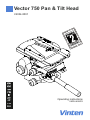
Vector 750
Pan and Tilt Head
Publication Part No. V4034-4980
Issue 3
English . . . . . . . . . . . . . . . . . . . . . . . . Page 2
Deutsch . . . . . . . . . . . . . . . . . . . . . . . Seite 19
Español . . . . . . . . . . . . . . . . . . . . . .Página 37
Français. . . . . . . . . . . . . . . . . . . . . . . Page 55
Italiano. . . . . . . . . . . . . . . . . . . . . . .Pagina 73
Português . . . . . . . . . . . . . . . . . . . .Página 91
日本語. . . . . . . . . . . . . . . . . . . . . . . ページ 109
中文 . . . . . . . . . . . . . . . . . . . . . . . . . . . 页码 127
Русский . . . . . . . . . . . . . . . . . . . . . . Стр 143
Copyright © Vitec Group plc 2012
All rights reserved throughout the world. No part of this document may be stored in a retrieval system,
transmitted, copied or reproduced in any way including, but not limited to, photocopy, photograph,
magnetic or other record without the prior agreement and permission in writing of Vitec Group plc.
Vinten®, Vector® and Quickfix® are registered trademarks of Vitec Group plc.

English
2
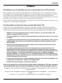
Preface
Thank you and congratulations on your new Vector 750 from Vinten
We want you to get the most from your new Vector 750 and therefore encourage you to read this operators
guide to familiarize yourself with its many features, some of which may be new to you. This document also
covers essential health and safety information and has a section on maintenance that will ensure you keep
your new product in perfect condition.
To receive additional benefits, register with Vinten now on line by visiting www.vinten.com/register.
Features and benefits of your new Vector 750
The Vector 750 has been specifically designed to meet the exacting demands of camera operators working
with full facility studio and OB cameras. The Vector 750 offers a high level of control with many unique
features.
• Suitable for a wide range of cameras, up to 75 kg (165.3 lb) with a C of G between 80–250 mm
(3–10 in.).
• Supplied complete with a standard wedge adaptor for easy and safe loading.
• The unique Perfect Balance system provides infinite adjustment, enabling perfect camera
balance to be achieved throughout the tilt range, regardless of drag setting.
• A retractable adjuster provides extensive camera fore and aft movement so that positioning
of the camera is easily controlled.
• "Fast action" can be easily followed as it happens with the responsive TF Drag control. It pro-
vides a wide range of infinitely adjustable drag from very light to extremely heavy, to suit any
operator's desire and is operational in extreme conditions down to - 40°C and up to + 60°C.
The TF drag system also allows for an extremely quick pan movement or "whip pan", recov-
ering instantly and with minimal spring back.
• The illuminated level bubble and back-lit display on the drag knobs allow for easy set up in
low light conditions.
• Easy to carry integral handle is a standard fitment.
Once again, thank you for choosing the Vector 750.
We are confident it will give you many years of reliable
performance.
Register your product to get One Extra Years Warranty and a
Free Vinten Quality Gift.
Please register now on-line at www.vinten.com/register - it's easy and fast.
Warranty Details and Terms and Conditions can be found on page 16.

English
3
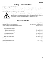
Safety - read this first
English—Original Instructions
The original instructions presented in this operators guide were written in English, and subsequently
translated into other languages. If you are unable to understand any of the translated languages, contact
Vinten or your distributor to obtain a translation of the original instructions (EU Countries).
Warning Symbols in this Operators Guide
Where there is a risk of personal injury or injury to others, comments appear
highlighted by the word WARNING!—supported by the warning triangle symbol.
Where there is a risk of damage to the product, associated equipment, process or
surroundings, comments appear highlighted by the word CAUTION!
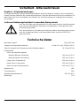
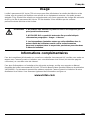
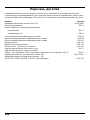
Technical Data
Maximum payload 75 kg (165.3 lb)
Payload Centre of Gravity height range 80 mm (3 in.) to 250 mm (10 in.)
Weight (complete with pan bar and wedge adaptor) 19.15 kg (42.1 lb)
Overall dimensions
Height (with wedge adaptor)
Minimum balance setting 255 mm (10.0 in.)
Maximum balance setting 355 mm (14.0 in.)
Length (without pan bar) 355 mm (14.0 in.)
Width (without pan bar) 350 mm (13.8 in.)
Width (with two pan bars) 445 mm (17.5 in.)
Tilt range ±52
Pan range 360
Operational temperature range -40C to 60C
Battery type PP3

English
4
Usage
The Vector 750 pan and tilt head is designed for use in broadcast and film studios to support and balance
a camera and ancillary equipment weighing up to 75 kg (165.3 lb), and must be mounted on equipment
designed to support a minimum payload of 95 kg (209 lbs.) The Vector 750 pan and tilt head is intended
for use by professional TV broadcast and film camera operators.
Further information
For further information or advice regarding this pan and tilt head, please contact Camera Dynamics
Limited, your local Vinten distributor (see back cover) or visit our website.
For details on maintenance and spare parts, please refer to the Vector 750 Pan and Tilt Head Maintenance
Manual and Illustrated Parts List (Publication Part No. V4034-4990) This is obtainable from Camera
Dynamics Limited or your local Vinten distributor. For information on-line, visit our website at
www.vinten.com
WARNING! 1. Do NOT attempt to use this product if you do not understand how to
operate it.
2. Do NOT use this product for any other purpose than that specified
in the Usage statement above.
3. Maintenance beyond that detailed in this Operators Guide must be
performed only by competent personnel in accordance with the
procedures specified in the Maintenance Manual.

English
5
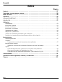
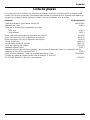
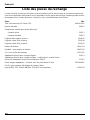
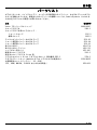
Contents
Page
Preface . . . . . . . . . . . . . . . . . . . . . . . . . . . . . . . . . . . . . . . . . . . . . . . . . . . . . . . . . . . . . . . . . . 2
Safety - read this first. . . . . . . . . . . . . . . . . . . . . . . . . . . . . . . . . . . . . . . . . . . . . . . . . . . . . . . . 3
Technical Data . . . . . . . . . . . . . . . . . . . . . . . . . . . . . . . . . . . . . . . . . . . . . . . . . . . . . . . . . . . . . 3
Usage . . . . . . . . . . . . . . . . . . . . . . . . . . . . . . . . . . . . . . . . . . . . . . . . . . . . . . . . . . . . . . . . . . . 4
Further information . . . . . . . . . . . . . . . . . . . . . . . . . . . . . . . . . . . . . . . . . . . . . . . . . . . . . . . . . 4
Introduction. . . . . . . . . . . . . . . . . . . . . . . . . . . . . . . . . . . . . . . . . . . . . . . . . . . . . . . . . . . . . . . 7
Operation
Unpacking. . . . . . . . . . . . . . . . . . . . . . . . . . . . . . . . . . . . . . . . . . . . . . . . . . . . . . . . . . . . . . . . . . . . . . 7
Mounting the head . . . . . . . . . . . . . . . . . . . . . . . . . . . . . . . . . . . . . . . . . . . . . . . . . . . . . . . . . . . . . . . 7
Pan bars . . . . . . . . . . . . . . . . . . . . . . . . . . . . . . . . . . . . . . . . . . . . . . . . . . . . . . . . . . . . . . . . . . . . . . . 8
Fitting a camera . . . . . . . . . . . . . . . . . . . . . . . . . . . . . . . . . . . . . . . . . . . . . . . . . . . . . . . . . . . . . . . . . 8
Balancing the head. . . . . . . . . . . . . . . . . . . . . . . . . . . . . . . . . . . . . . . . . . . . . . . . . . . . . . . . . . . . . . . 9
Locking the platform . . . . . . . . . . . . . . . . . . . . . . . . . . . . . . . . . . . . . . . . . . . . . . . . . . . . . . . . . . . . . 10
Pan and tilt brakes . . . . . . . . . . . . . . . . . . . . . . . . . . . . . . . . . . . . . . . . . . . . . . . . . . . . . . . . . . . . . . 10
Pan and tilt drag . . . . . . . . . . . . . . . . . . . . . . . . . . . . . . . . . . . . . . . . . . . . . . . . . . . . . . . . . . . . . . . . 10
Servicing
General. . . . . . . . . . . . . . . . . . . . . . . . . . . . . . . . . . . . . . . . . . . . . . . . . . . . . . . . . . . . . . . . . . . . . . . 11
Cleaning
Cleaning balance mechanism tracks . . . . . . . . . . . . . . . . . . . . . . . . . . . . . . . . . . . . . . . . . . . . . 11
Routine maintenance
Level bubble illumination unit battery replacement. . . . . . . . . . . . . . . . . . . . . . . . . . . . . . . . . . . 12
Adjustments
Platform slide clamp adjustment. . . . . . . . . . . . . . . . . . . . . . . . . . . . . . . . . . . . . . . . . . . . . . . . .13
Repositioning the wedge adaptor. . . . . . . . . . . . . . . . . . . . . . . . . . . . . . . . . . . . . . . . . . . . . . . . 13
Pan and tilt brake adjustment. . . . . . . . . . . . . . . . . . . . . . . . . . . . . . . . . . . . . . . . . . . . . . . . . . . 13
Parts List
. . . . . . . . . . . . . . . . . . . . . . . . . . . . . . . . . . . . . . . . . . . . . . . . . . . . . . . . . . . . . . . . 15
Warranty Details and Terms and Conditions . . . . . . . . . . . . . . . . . . . . . . . . . . . . . . . . . . . . . . 16
Figures . . . . . . . . . . . . . . . . . . . . . . . . . . . . . . . . . . . . . . . . . . . . . . . . . . . . . . . . . . . . . . . 161

English
6
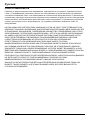
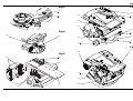
Vector 750 Pan & Tilt Head (Left-hand Side) (Fig 1)
(1) Wedge adaptor
(2) Wedge adaptor operating lever
(3) Wedge adaptor securing screw
(4) Pan brake lever
(5) Tilt brake lever
(6) Carrying handle
(7) Level bubble illumination switch
(8) Level bubble
(9) Pan drag adjustment knob
(10) Pan bar clamp
(11) Tilt drag adjustment knob
(12) Slide plate clamp
(13) Slide plate adjustment knob
Vector 750 Pan & Tilt Head (Right-hand Side) (Fig 2)
(14) Slide plate
(15) Balance adjustment knob
(16) Centre lock button
(17) Centre lock release catch
(18) Pan bar mounting
Vector 750 Pan & Tilt Head (Underside) (Fig 3)
(19) Four bolt fixing
(20) Bolt hole position indicator

English
7
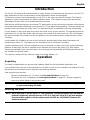
Introduction
The Vector 750 pan and tilt head embodies a unique linkage counterbalancing mechanism, thin film (TF)
drag assemblies for pan and tilt motions and an adjustable camera mounting plate.
The balance system is easily adjusted by a knob (15) on the right-hand side of the head. The balance
adjustment control compensates for differing platform load C of G heights by varying the mechanical
advantage of a bell-crank in the counterbalance mechanism.
Both the pan and tilt mechanisms incorporate TF drag systems to ensure smooth movement of the camera
about these axes and are fitted with control knobs (9), (11) to adjust the drag setting. The drag controls are
mounted on the left-hand side of the head. The whip-pan facility is unaffected by the pan drag setting.
Friction brakes on each axis allow the head to be locked at any chosen position. The operating levers for
both brakes (4), (5) are fitted at the right-hand rear of the head. A tilt axis centre lock (16) is provided on
the right-hand side of the head to secure the platform in the horizontal position during transport or load
changing.
A level bubble (8) is fitted to the rear of the head and is provided with a time-delay illumination unit,
operated by a switch (7). The battery for the illumination unit is contained in the base.
Pan bar mounting points (18) are located at the rear of the head, on either side of the camera mounting
platform. A telescopic pan bar is supplied and is attached using a pan bar clamp (10), with angular
adjustment available on the mount serrations. A second pan bar may be fitted, and fixed and short pan bars
are available as optional extras.
The camera is attached to the head by means of a wedge adaptor (1).
Operation
Unpacking
The head is supplied with one pan bar and a battery (fitted) for the level bubble illumination unit.
A second telescopic pan bar or short pan bar for use with a zoom or focus controller are optional. Ensure
that all items are unpacked prior to disposal of the packing materials.
After unpacking ensure that:
The pan and tilt brakes (4), (5) are on (see Pan and tilt brakes on page 10).
The centre lock (16) is engaged (see Locking the platform on page 10). Always engage the
centre lock before lifting or carrying the head.
Mounting the head
CAUTION! Do NOT Lift the head by the platform. Only use the base and/or the carrying handle
to prevent damaging the head.
NOTE: When mounted on Vinten ‘Hawk’ or ‘Teal’ pedestals, clearance between the head and the
pedestal weight tray prevents the use of 5.5 lb (1.6 kg) and 1.0 lb (0.47 kg) trim weights.
Use alternative weights or fit the adaptor plate kit (Part No. 3354-900SP) between the
head and pedestal.

English
8
The head is mounted on a tripod, pedestal or suitable firm surface using the four fixing bolts and washers.
The four bolt fixing holes (19) on the underside of the head are easily located using the bolt hole position
indicators (20). Tighten the bolts with the spanner provided.
After mounting the head, ensure it is level using the level bubble (8), which may be may be illuminated by
pressing the switch (7). The light will go out after approximately 15-seconds.
Pan bars
Fit the pan bars to the head and adjust the position of each one before tightening the clamp (10) on the
mounting (18). Adjust the length of the telescopic pan bars.
Fitting a camera
To fit a camera, proceed as follows:
Lower the mounting to a convenient working height.
If not already fitted, install the wedge adaptor (1) in the middle position on the slide plate (14) (see
Repositioning the wedge adaptor on page 13).
Attach the wedge to the camera/lens.
Ensure that the centre lock (16) is engaged (see Locking the platform on page 10).
Apply the pan brake (4) (see Pan and tilt brakes on page 10)
.
Slide the wedge adaptor operating lever (2) forward (parallel to the wedge) about 6 mm (1/4 in.)
against spring tension. Pull the operating lever out, away from the body of the wedge adaptor, as
far as it will go.
Insert the camera wedge into the wedge adaptor and push it forward into full engagement. Push in
the operating lever (1) until it lies parallel with the wedge adaptor body. During this operation
resistance of the spring-loaded over-centre mechanism will be felt. As the lever reaches the end
of its travel it will slide back (parallel to the wedge) to the locked position.
Confirm that the lever is in the locked position. This is indicated by coloured bands above the lever.
When the green band only is visible, the lever is locked. If any of the red band can be seen, the
lever is not locked.
Install the remainder of the payload (lens, zoom and focus controls, viewfinder, prompter etc.).
WARNING! 1. Only mount this product on equipment designed to support a
minimum of 95 kg (109 lbs.).
2. Before installing the head, hold a fixing bolt in position and check
that the threaded end does not project more than 20 mm (3/4 in.)
above the mounting face.
WARNING! 1. Do NOT rely on the tilt brake when changing the payload. Always
engage the centre lock.
2. Ensure that the weight and C of G height of the total payload is
within the range for which the head is designed: up to 75 kg (167.3 lb)
with C of G height from 80 mm (3 in) to 250 mm (10 in).

English
9
Balancing the head
Balancing the head consists of positioning the payload fore and aft on the head so that its C of G is
immediately above the platform pivot, then compensating for the payload C of G height using the balance
adjustment knob.
Position the payload fore and aft as follows:
Ensure that the centre lock is engaged (see Locking the platform on page 10) and that the
camera and all accessories are fitted.
Turn the tilt drag adjustment knob (11) to its minimum setting.
Holding the pan bar to steady the platform, disengage the centre lock (see Locking the platform
on page 10).
Push the clamp lever (12) downward to release the slide plate clamp and pull out the slide plate
adjustment knob (13) until it engages with the platform drive. Turn the knob to move the slide plate
fore and aft to achieve horizontal balance.
The horizontal balance is correct when no perceptible tilting force can be felt on the pan bar with
the platform level. Apply the slide plate clamp (12) by pulling the clamp lever upward.
If there is insufficient movement in the slide plate to achieve balance, reposition the wedge adaptor
(see Servicing on page 11), refit the load and repeat the horizontal balancing procedure.
When fore and aft balance has been achieved, adjust the payload C of G height as follows:
Using the pan bar, tilt the platform forward and backward. When correctly balanced, there should
be no perceptible tilting force on the pan bar at any angle of tilt and the head should remain in any
tilt position to which it is set.
If the head tends to fall away when the platform is tilted, push in and turn the balance adjustment
knob (15) clockwise to increase the C of G height setting. If the head tends to spring back to centre,
push in and turn the balance adjustment knob (15) counter-clockwise to decrease the C of G height
setting.
When the payload C of G height adjustment is complete, check that the fore and aft balance
remains satisfactory. Re-adjust the position of the slide plate if necessary.
After balancing, release the brakes and exercise the head through both axes to confirm that it operates
smoothly.
NOTE: It is important that the pan bar(s) and all camera accessories (lens, zoom and focus
controls, viewfinder, prompter etc.) are fitted in their operational position before
balancing the head. Any equipment fitted or adjusted later will unbalance the head.
WARNING! Increase the balance setting (15) for a heavy out-of-balance payload
BEFORE disengaging the centre lock (16), to prevent the platform
tipping violently.
NOTE: The balance adjustment knob is a multi-turn control. To enable the knob to be turned
more easily, slightly tilt the platform using the pan bar whilst turning the knob.

English
10
Locking the platform
(Fig 4)
The centre lock mechanism is operated by a button (16) on the right-hand side of the head. To engage the
lock, hold the platform in the horizontal position and push the button (16) inwards until it latches and the
release catch (17) appears. Use the pan bar to rock the platform slightly whilst pushing the button (16).
To release the centre lock, rock the platform slightly and push down on the release catch (17).
Pan and tilt brakes
The pan and tilt brakes are operated by levers (4), (5) at the rear of the head. They are applied by pulling
the appropriate lever up and back and released by pushing the lever forwards.
The brakes should be applied whenever the camera is left unattended.
Pan and tilt drag
The pan drag adjustment knob (9) is mounted on the left-hand lower part of the main body. Tilt drag is
adjusted by a knob (11) mounted on the face of the tilt drag housing on the left-hand side of the head. The
drag adjustment knobs are graduated from 0 (minimum drag) to 9 (maximum drag).
Turn the knobs clockwise to increase drag and counter-clockwise to decrease drag.

English
11
Servicing
General
The Vector 750 pan and tilt head is robustly made to high engineering standards and little attention is
required to maintain serviceability save regular cleaning.
Routine maintenance on the Vector 750 pan and tilt head is limited to annual replacement of the level
bubble illumination battery. No further routine maintenance is required.
During normal use, check the effectiveness of the platform slide clamp and the adequacy of level bubble
illumination.
Refer to the appropriate section in the Maintenance Manual if any defect is apparent. Adjustments and
repairs should be carried out only by a competent person.
Cleaning
During normal use the only cleaning required should be a regular wipe over with a lint-free cloth. Dirt
accumulated during storage or periods of disuse may be removed with a semi-stiff brush. Particular
attention should be paid to the wedge location faces of the wedge adaptor.
Use out-of-doors under adverse conditions may require special attention, and the head should be covered
when not in use. Salt spray should be washed off using fresh water at the earliest opportunity. Sand and
dirt act as an abrasive and should be removed using a semi-stiff brush or a vacuum cleaner.
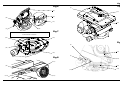
Cleaning balance mechanism tracks
The balance mechanism tracks are automatically cleaned by built-in wipers, but after use in particularly
adverse conditions the tracks may require cleaning. Some dismantling of the head is necessary and it is
recommended that this be carried out in clean workshop conditions.
Vertical tracks
(Fig 5)
To clean the vertical tracks it is necessary to remove the platform. Proceed as follows:
Remove the payload (if fitted). It is not necessary to remove the wedge adaptor.
Release the slide plate clamp (12). Use the adjustment knob (13) to wind the slide plate (14)
backwards until it is clear of fixing screws (21).
Level the platform.
Remove six screws (21) securing the platform (22) to the balance mechanism (23). Lift off the
platform.
Using a pipe cleaner (or similar) moistened with an isopropanol-based cleaner (3M VBH or similar),
and clean the two vertical tracks (24). Upwards pressure on the balance mechanism will allow the
area of track under the vertical rollers to be cleaned.
Install the platform (22) on the balance mechanism (23) and secure with six screws (21), using
Loctite 222E.
Using the adjustment knob (13) wind the slide plate forwards to the central position.
Refit the payload (if required) and rebalance the head.
CAUTION!
DO NOT use solvent- or oil-based cleaners, abrasives or wire brushes to remove
accumulations of dirt as these damage the protective surfaces. To clean
mechanical surfaces, use only detergent-based cleaners.

English
12
Horizontal tracks
(Fig 6)
No dismantling is necessary to clean the horizontal tracks. Proceed as follow:
Remove the payload (if fitted).
Set the balance mechanism to its maximum setting by pushing in the knob (15) and turning it
clockwise to its stop.
Tilt the platform fully backwards and apply the tilt brake (5).
Pull down the flap guard (28) to reveal the bevel gear (26). Access to the horizontal tracks (27) is
through the holes in the bevel gear, which may be rotated freely.
Using a pipe cleaner (or similar) moistened with an isopropanol-based cleaner (3M VBH or similar),
clean the two horizontal tracks. Upwards pressure on the balance mechanism will allow the area
of track under the horizontal rollers to be cleaned.
Release the flap guard (28) and the tilt brake (5) and return the platform to the horizontal position.
Refit the payload (if required).
Routine maintenance
Level bubble illumination unit battery replacement
(Fig 7)
The level bubble on the Vector 750 pan and tilt head is illuminated by a battery-powered light-emitting diode
(LED). A time-delay circuit initiated by a switch controls the LED. The battery should be replaced at yearly
intervals or whenever the illumination is considered inadequate.
To install or replace the battery:
Remove three screws (29) which secure the battery compartment cover plate (32) to the head.
Install or replace the battery (30), pushing the connector (31) onto the battery terminals.
Position the battery in the battery compartment, ensuring that the wiring is not trapped.
Refit the battery cover plate (32), ensuring battery locates in cover plate. Secure with three screws
(29).
Press the switch (7) and ensure the lamp is lit for approximately 15-seconds.
Adjustments
After considerable use the platform slide clamp may require adjustment.
To enable the payload to be correctly balanced, the wedge adaptor may require repositioning.
The pan and tilt brakes may require adjustment after considerable use.
NOTE: Dependent on the type of mounting, it may be necessary to remove the head from the
mounting for access to the battery compartment.

English
13
Platform slide clamp adjustment
(Fig 8)
The platform slide clamp (12) should be set so that, in the up or clamped position it prevents the platform
slide from being moved, while in the down or released position it allows free adjustment of the slide. To
adjust the clamp, proceed as follows:
On the left-hand side of the platform, carefully remove the plastic cap (12.2) to reveal the slotted
shaft (12.1).
Pull the slide clamp lever (12) fully upwards.
Slacken the clamp screw (12.3).
Turn the slotted shaft (12.1) fully clockwise to apply the clamp.
Tighten the clamp screw (12.3).
Move the lever over its full range and ensure that, in the clamped position, it prevents the slide from
being moved, while in the released position it allows free adjustment of the slide. Re-adjust if
necessary.
Replace the plastic cap (12.2) over the slotted shaft (12.1).
Repositioning the wedge adaptor
(Fig 9)
The wedge adaptor (1) is secured by four cap head screws (3) which pass through the wedge adaptor into
the slide plate (14).
To reposition the wedge adaptor:
Engage the centre lock (see Locking the platform on page 10) and remove the load.
Hold the body of the wedge adaptor (1) and use a 4 mm hexagon wrench to remove four securing
screws (3).
Reposition the wedge adaptor (1) on the slide plate (14), ensuring that the narrow end of the wedge
adaptor faces forwards.
Insert the four screws (3) in the holes in the wedge adaptor and tighten.
Pan and tilt brake adjustment
(Fig 10)
The pan and tilt brakes should be set so that the brakes begin to be applied after approximately one-third
of the lever travel.
The tilt brake is adjusted by inserting a 2 mm hexagon wrench through the hole (5.2) in the bottom of the
tilt unit cover and turning the grub screw (5.1). To adjust the tilt brake, proceed as follows:
Operate the tilt brake lever (5) from the OFF to the ON position.
If brake pressure is not felt after approximately one-third of the lever travel, turn the grub screw
(5.1) clockwise until this is achieved.
Operate the tilt brake lever (5) to the OFF position and ensure that the platform is free to move.
WARNING! Overlong screws will prevent the slide plate from operating. Always
use the screws provided (M6 x 30 mm).

English
14
The pan brake is adjusted by turning the pin (4.3). To gain access to the pin it is necessary to remove the
payload from the head, remove the head from its mounting and remove a cover plate (4.1) from the
underside of the head. To adjust the pan brake, proceed as follows:
Remove the payload from the head.
Remove the head from its mounting.
On the underside of the head, remove three screws (4.2) securing cover plate (4.1).
Operate the pan brake lever (4) from the OFF to the ON position.
If brake pressure is not felt after approximately one-third of the lever travel, turn the pin (4.3)
clockwise until this is achieved.
Operate the pan brake lever (4) to the OFF position and ensure that the head is free to rotate.
Refit cover plate (4.1) and secure with three screws (4.2).
WARNING! Remove the payload before adjusting the pan brake.

English
15
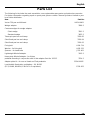
Parts List
The following list includes the main assemblies, user-replaceable spare parts and optional accessories.
For further information regarding repair or spare parts, please contact Camera Dynamics Limited or your
local Vinten distributor.
Item Part No.
Vector 750 pan and tilt head V4034-0001
Wedge adaptor 3389-3
Camera wedges for wedge adaptor:
Short wedge 3391-3
Standard wedge 3053-3
Telescopic pan bar and clamp 3219-82
Short fixed pan bar and clamp 3219-94
Short fixed pan bar and clamp 3219-93
Fixing bolt L054-714
Washer - for fixing bolt L602-122
Spanner - for head bolts J551-001
Lightweight Mitchell adaptor 3103-3
Heavy-duty Mitchell adaptor - for Vinten
pedestal mounting in conjunction with Hi-hat adaptor Part No. 3055-3 3724-3
Adaptor plate kit - for use on Hawk and Teal pedestals 3354-900SP
Level bubble illumination unit battery - 9V, 6LR61
(PP3, 6AM6, MN1604, E-BLOCK or equivalent) C550-023

16
Warranty Details and Terms and Conditions
Please read the Warranty Details and Terms and Conditions below.
Register your product to get One Extra Years Warranty and a Free
Vinten Quality Gift.
Please register now on-line at www.vinten.com/register - it's easy and fast.
The product serial number location (25) is shown in Fig 6.
Warranty
Vinten warrants, to the original purchaser only, that this product will be free from defects in materials and
workmanship under normal and proper usage for a period of one (1) year from the date of purchase.
Vinten's obligation under this warranty is limited to replacing or repairing, at Vinten's option, products or
parts determined by Vinten to be defective in materials or workmanship. This Vinten parts and labour
warranty is subject to the terms and conditions set forth below.
Extended Warranty
By registering on-line, the warranty on Vinten hardware products described above is extended from one
(1) to two (2) years from the date of purchase subject to the terms and conditions below.
Terms and Conditions
Notification of Warranty Claims
All warranty claims must be made in writing and must include date and proof of purchase
Extent of liability
This warranty is given to the original purchaser of the goods only and cannot be assigned, except with the
prior written agreement of Vinten.
Subject to these terms and conditions, Vinten will repair or replace, free of charge, any product or defective
part provided that the defective part of the product has been returned to Vinten or its authorized agent,
freight pre-paid.
If any defective product has been superseded and cannot be repaired, replacement will be made with a
current model of the same quality and equivalent function.
Exclusion of Liability
This warranty does not cover any damage, defects or costs caused by: (1) modification, alteration, repair
or service of the product by anyone other than Vinten or its authorized representative; (2) physical abuse
to, overload of, or misuse of, the product, or operation of the product in a manner contrary to the instructions
accompanying the product; (3) any use of the product other than that for which it was intended; or (4)
shipment of the product to Vinten for service.
UNDER NO CIRCUMSTANCES SHALL VINTEN BE LIABLE FOR ANY SPECIAL, INCIDENTAL OR
CONSEQUENTIAL DAMAGES, INCLUDING, BUT NOT LIMITED TO, PERSONAL INJURY, PROPERTY
DAMAGE, DAMAGE TO OR LOSS OF EQUIPMENT, LOST PROFITS OR REVENUE, COSTS OF
RENTING REPLACEMENTS AND OTHER ADDITIONAL EXPENSES, EVEN IF VINTEN HAS BEEN
ADVISED OF THE POSSIBILITY OF SUCH DAMAGES. SOME JURISDICTIONS DO NOT ALLOW THE

English
17
EXCLUSION OR LIMITATION OF INCIDENTAL OR CONSEQUENTIAL DAMAGES, SO THE ABOVE
LIMITATION OR EXCLUSION MAY NOT APPLY TO YOU.
ANY EXPRESS WARRANTY NOT PROVIDED HEREIN, AND ANY REMEDY WHICH, BUT FOR THE
WARRANTY CONTAINED HEREIN, MIGHT ARISE BY IMPLICATION OR OPERATION OF LAW IS
HEREBY EXCLUDED AND DISCLAIMED INCLUDING THE IMPLIED WARRANTIES OF
MERCHANTABILITY AND OF FITNESS FOR A PARTICULAR PURPOSE. SOME JURISDICTIONS DO
NOT ALLOW LIMITATIONS ON IMPLIED WARRANTIES, SO THE ABOVE LIMITATION MAY NOT
APPLY TO YOU.
THIS WARRANTY GIVES YOU SPECIFIC LEGAL RIGHTS AND YOU MAY ALSO HAVE OTHER
RIGHTS, WHICH MAY VARY FROM JURISDICTION TO JURISDICTION.

18

Deutsch
19
Vorwort
Vielen Dank und Herzlichen Glückwunsch zum Kauf Ihres neuen Vector 750
von Vinten
Wir möchten, dass Sie Ihren neuen Vector 750 optimal nutzen können und empfehlen Ihnen daher, dieses
Bedienungshandbuch sorgfältig zu lesen, um sich mit seinen zahlreichen Merkmalen vertraut zu machen,
von denen Ihnen einige möglicherweise neu sind. Dieses Dokument enthält zudem wichtige Sicherheits-
und Unfallverhütungsinformationen und verfügt über einen Abschnitt zu Instandhaltung und Pflege, der
Ihnen dabei hilft, den perfekten Zustand Ihres neuen Produkts zu erhalten.
Registrieren Sie sich jetzt online bei Vinten unter www.vinten.com/register und genießen Sie weitere
Vorteile.
Merkmale und Leistungseigenschaften Ihres neuen Vector 750
Der Vector 750 wurde speziell mit Blick auf die hohen Ansprüche von Kameraleuten für die Arbeit mit
umfassend einsetzbaren Studio- und OB-Kameras entwickelt. Der Vector 750 bietet neben einer
hervorragenden Bedienung zahlreiche einzigartige Merkmale.
• Geeignet für eine breite Palette von Kameras, bis zu 75 kg (165,3 lb) mit einem Schwerpunkt
von 80–250 mm (3–10 in.).
• Zum Lieferumfang gehört ein standardmäßiger Keilplattenadapter zum bequemen und siche-
ren Laden.
• Das einzigartige "Perfect Balance"-System bietet eine stufenlose Einstellung, wodurch,
unabhängig von der Dämpfungseinstellung, eine perfekte Kamerabalance über den ge-
samten Neigebereich erzielt werden kann.
• Ein ausziehbarer Einsteller erlaubt eine weitreichende Plattformverschiebung, mit der sich
die Position der Kamera bequem steuern lässt.
• "Schnelle Action" kann dank des Ansprechverhaltens der Dünnfilm-Dämpfungssteuerung
(TF) problemlos "live" verfolgt werden.Der umfangreiche, stufenlos von sehr leicht bis ext-
rem schwer einstellbare Dämpfungsbereich passt sich jedem Wunsch des Anwenders an
und ist auch unter extremen Bedingungen bis zu - 40°C und + 60°C einsetzbar. Das
TF-Dämpfungssystem ermöglicht zudem eine äußerst schnelle Schwenkbewegung, den so
genannten "Reißschwenk", und kehrt sofort danach und mit minimaler Rückfederung in die
Ausgangsstellung zurück.
• Die beleuchtete Nivellierlibelle und die hintergrundbeleuchtete Anzeige auf den Dämpfungs-
einstellern gewährleisten eine bequeme Einstellung auch bei schlechten Lichtverhältnissen.
• Zur Standardausstattung gehört ebenfalls ein integrierter Tragegriff zum einfachen
Transport.
Wir bedanken uns noch einmal, dass Sie sich für den Vector 750 entschieden
haben. Wir sind sicher, dass er Ihnen viele Jahre lang verlässliche Leistung
bieten wird.
Wenn Sie Ihr Produkt registrieren, erhalten Sie eine Einjährige Garantieverlängerung und
zusätzlich ein Geschenk in Vinten-Qualität.
Bitte registrieren Sie sich jetzt gleich online unter www.vinten.com/register - einfach und
schnell.
Einzelheiten zur Garantie und Allgemeine Geschäftsbedingungen finden Sie auf Seite 34.
La page est en cours de chargement...
La page est en cours de chargement...
La page est en cours de chargement...
La page est en cours de chargement...
La page est en cours de chargement...
La page est en cours de chargement...
La page est en cours de chargement...
La page est en cours de chargement...
La page est en cours de chargement...
La page est en cours de chargement...
La page est en cours de chargement...
La page est en cours de chargement...
La page est en cours de chargement...
La page est en cours de chargement...
La page est en cours de chargement...
La page est en cours de chargement...
La page est en cours de chargement...
La page est en cours de chargement...
La page est en cours de chargement...
La page est en cours de chargement...
La page est en cours de chargement...
La page est en cours de chargement...
La page est en cours de chargement...
La page est en cours de chargement...
La page est en cours de chargement...
La page est en cours de chargement...
La page est en cours de chargement...
La page est en cours de chargement...
La page est en cours de chargement...
La page est en cours de chargement...
La page est en cours de chargement...
La page est en cours de chargement...
La page est en cours de chargement...
La page est en cours de chargement...
La page est en cours de chargement...
La page est en cours de chargement...
La page est en cours de chargement...
La page est en cours de chargement...
La page est en cours de chargement...
La page est en cours de chargement...
La page est en cours de chargement...
La page est en cours de chargement...
La page est en cours de chargement...
La page est en cours de chargement...
La page est en cours de chargement...
La page est en cours de chargement...
La page est en cours de chargement...
La page est en cours de chargement...
La page est en cours de chargement...
La page est en cours de chargement...
La page est en cours de chargement...
La page est en cours de chargement...
La page est en cours de chargement...
La page est en cours de chargement...
La page est en cours de chargement...
La page est en cours de chargement...
La page est en cours de chargement...
La page est en cours de chargement...
La page est en cours de chargement...
La page est en cours de chargement...
La page est en cours de chargement...
La page est en cours de chargement...
La page est en cours de chargement...
La page est en cours de chargement...
La page est en cours de chargement...
La page est en cours de chargement...
La page est en cours de chargement...
La page est en cours de chargement...
La page est en cours de chargement...
La page est en cours de chargement...
La page est en cours de chargement...
La page est en cours de chargement...
La page est en cours de chargement...
La page est en cours de chargement...
La page est en cours de chargement...
La page est en cours de chargement...
La page est en cours de chargement...
La page est en cours de chargement...
La page est en cours de chargement...
La page est en cours de chargement...
La page est en cours de chargement...
La page est en cours de chargement...
La page est en cours de chargement...
La page est en cours de chargement...
La page est en cours de chargement...
La page est en cours de chargement...
La page est en cours de chargement...
La page est en cours de chargement...
La page est en cours de chargement...
La page est en cours de chargement...
La page est en cours de chargement...
La page est en cours de chargement...
La page est en cours de chargement...
La page est en cours de chargement...
La page est en cours de chargement...
La page est en cours de chargement...
La page est en cours de chargement...
La page est en cours de chargement...
La page est en cours de chargement...
La page est en cours de chargement...
La page est en cours de chargement...
La page est en cours de chargement...
La page est en cours de chargement...
La page est en cours de chargement...
La page est en cours de chargement...
La page est en cours de chargement...
La page est en cours de chargement...
La page est en cours de chargement...
La page est en cours de chargement...
La page est en cours de chargement...
La page est en cours de chargement...
La page est en cours de chargement...
La page est en cours de chargement...
La page est en cours de chargement...
La page est en cours de chargement...
La page est en cours de chargement...
La page est en cours de chargement...
La page est en cours de chargement...
La page est en cours de chargement...
La page est en cours de chargement...
La page est en cours de chargement...
La page est en cours de chargement...
La page est en cours de chargement...
La page est en cours de chargement...
La page est en cours de chargement...
La page est en cours de chargement...
La page est en cours de chargement...
La page est en cours de chargement...
La page est en cours de chargement...
La page est en cours de chargement...
La page est en cours de chargement...
La page est en cours de chargement...
La page est en cours de chargement...
La page est en cours de chargement...
La page est en cours de chargement...
La page est en cours de chargement...
La page est en cours de chargement...
La page est en cours de chargement...
La page est en cours de chargement...
La page est en cours de chargement...
La page est en cours de chargement...
La page est en cours de chargement...
La page est en cours de chargement...
La page est en cours de chargement...
-
 1
1
-
 2
2
-
 3
3
-
 4
4
-
 5
5
-
 6
6
-
 7
7
-
 8
8
-
 9
9
-
 10
10
-
 11
11
-
 12
12
-
 13
13
-
 14
14
-
 15
15
-
 16
16
-
 17
17
-
 18
18
-
 19
19
-
 20
20
-
 21
21
-
 22
22
-
 23
23
-
 24
24
-
 25
25
-
 26
26
-
 27
27
-
 28
28
-
 29
29
-
 30
30
-
 31
31
-
 32
32
-
 33
33
-
 34
34
-
 35
35
-
 36
36
-
 37
37
-
 38
38
-
 39
39
-
 40
40
-
 41
41
-
 42
42
-
 43
43
-
 44
44
-
 45
45
-
 46
46
-
 47
47
-
 48
48
-
 49
49
-
 50
50
-
 51
51
-
 52
52
-
 53
53
-
 54
54
-
 55
55
-
 56
56
-
 57
57
-
 58
58
-
 59
59
-
 60
60
-
 61
61
-
 62
62
-
 63
63
-
 64
64
-
 65
65
-
 66
66
-
 67
67
-
 68
68
-
 69
69
-
 70
70
-
 71
71
-
 72
72
-
 73
73
-
 74
74
-
 75
75
-
 76
76
-
 77
77
-
 78
78
-
 79
79
-
 80
80
-
 81
81
-
 82
82
-
 83
83
-
 84
84
-
 85
85
-
 86
86
-
 87
87
-
 88
88
-
 89
89
-
 90
90
-
 91
91
-
 92
92
-
 93
93
-
 94
94
-
 95
95
-
 96
96
-
 97
97
-
 98
98
-
 99
99
-
 100
100
-
 101
101
-
 102
102
-
 103
103
-
 104
104
-
 105
105
-
 106
106
-
 107
107
-
 108
108
-
 109
109
-
 110
110
-
 111
111
-
 112
112
-
 113
113
-
 114
114
-
 115
115
-
 116
116
-
 117
117
-
 118
118
-
 119
119
-
 120
120
-
 121
121
-
 122
122
-
 123
123
-
 124
124
-
 125
125
-
 126
126
-
 127
127
-
 128
128
-
 129
129
-
 130
130
-
 131
131
-
 132
132
-
 133
133
-
 134
134
-
 135
135
-
 136
136
-
 137
137
-
 138
138
-
 139
139
-
 140
140
-
 141
141
-
 142
142
-
 143
143
-
 144
144
-
 145
145
-
 146
146
-
 147
147
-
 148
148
-
 149
149
-
 150
150
-
 151
151
-
 152
152
-
 153
153
-
 154
154
-
 155
155
-
 156
156
-
 157
157
-
 158
158
-
 159
159
-
 160
160
-
 161
161
-
 162
162
-
 163
163
-
 164
164


dans d''autres langues
- italiano: Vinten Vector 750 Istruzioni per l'uso
- español: Vinten Vector 750 Instrucciones de operación
- Deutsch: Vinten Vector 750 Bedienungsanleitung
- português: Vinten Vector 750 Instruções de operação
- 日本語: Vinten Vector 750 取扱説明書
Documents connexes
-
Vinten Vector 75 Operator Guide
-
-
Vinten Vector 950 Manuel utilisateur
-
Vinten Vector 90 Mode d'emploi
-
-
-
-
-
-