Simplicity 076001- Manuel utilisateur
- Catégorie
- Groupes électrogènes
- Taper
- Manuel utilisateur
Ce manuel convient également à

Operator’s Manual
Liquid-Cooled
Home Generator System
Not for
Reproduction

Thank you for purchasing this quality-built Briggs & Stratton home generator. We’re pleased that you’ve placed your
confidence in the Briggs & Stratton brand. When operated and maintained according to the instructions in this manual, your
home generator will provide many years of dependable service.
This manual contains safety information to make you aware of the hazards and risks associated with home standby
generators and how to avoid them. Because we do not necessarily know all the applications this equipment could be used
for, it is important that you read and understand these instructions thoroughly before attempting to start or operate this
equipment. Save these instructions for future reference.
This home generator requires professional installation before use. Refer to the separate installation manual for full
information. Your installer should follow the instructions completely.
Where to Find Us
You never have to look far to find Briggs & Stratton support and service for your generator. Consult your Yellow Pages. There
are thousands of Briggs & Stratton authorized service dealers worldwide who provide quality service. You can also contact
Technical Service by phone at (800) 743‑4115, or click on Find a Dealer at BRIGGSandSTRATTON.COM, which provides a list
of authorized dealers.
Generator and engine model and serial numbers should be recorded in the installation manual.
Briggs & Stratton Power Products Group, LLC
900 North Parkway
Jefferson, WI 53549
Copyright © 2009. All rights reserved. No part of this material
may be reproduced or transmitted in any form without the express
written permission of Briggs & Stratton Power Products Group, LLC.
Not for
Reproduction

3
Table of Contents
Important Safety Instructions........................4
Installation ....................................7
For the Installing Dealer/Contractor: ..............................7
Owner Orientation ............................................7
Fuel Factors .................................................7
Generator Location............................................8
Essential Circuits .............................................8
Delivery Inspection...........................................10
Controls ..................................... 11
30 kW Home Generator .......................................11
45 kW Home Generator .......................................12
System Control Panel.........................................13
Access Ports ...............................................14
Operation .................................... 15
Automatic Operation .........................................15
Setting Exercise Timer ........................................16
Maintenance .................................. 16
Fault Detection System .......................................16
Generator Maintenance .......................................18
Engine Oil..................................................18
Battery ....................................................19
Storage....................................................20
Troubleshooting................................ 21
Warranty..................................... 22
Product Specifications ........................... 24
Not for
Reproduction

4 BRIGGSandSTRATTON.COM
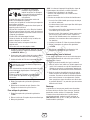
SAVE THESE INSTRUCTIONS - This manual contains
important instructions that should be followed during
installation and maintenance of the generator and batteries.
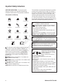
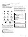
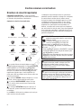
Safety Symbols and Meanings
The safety alert symbol indicates a potential personal
injury hazard. A signal word (DANGER, WARNING, or
CAUTION) is used with the alert symbol to designate a
degree or level of hazard seriousness. A safety symbol
may be used to represent the type of hazard. The signal
word NOTICE is used to address practices not related to
personal injury.
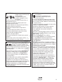
DANGER indicates a hazard which, if not avoided, will
result in death or serious injury.
WARNING indicates a hazard which, if not avoided, could
result in death or serious injury.
CAUTION indicates a hazard which, if not avoided, could
result in minor or moderate injury.
NOTICE addresses practices not related to personal injury.
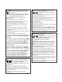
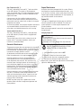
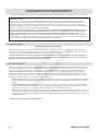
Important Safety Instructions
Fire
Toxic Fumes
Explosive Pressure
Rotating Fan Blade
Lift Hazard Read Manual
Exploding BatteryRotating Belt/Pulley
Chemical BurnAuto Start
Hot SurfaceRotating Parts
Electrical ShockExplosion
The manufacturer cannot possibly anticipate every possible
circumstance that might involve a hazard. The warnings in
this manual, and the tags and decals affixed to the unit are,
therefore, not all-inclusive. If you use a procedure, work
method or operating technique that the manufacturer does
not specifically recommend, you must satisfy yourself that
it is safe for you and others. You must also make sure that
the procedure, work method or operating technique that you
choose does not render the generator system unsafe.
WARNING Running engine gives off carbon monoxide,
an odorless, colorless, poison gas.
Breathing carbon monoxide can cause headache,
fatigue, dizziness, vomiting, confusion, seizures,
nausea, fainting or death.
Operate generator ONLY outdoors.•
Install a battery operated carbon monoxide alarm near •
the bedrooms.
Keep exhaust gas from entering a confined area through •
windows, doors, ventilation intakes, or other openings.
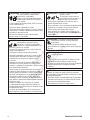
WARNING The engine exhaust from this product
contains chemicals known to the State of California to
cause cancer, birth defects, or other reproductive harm.
WARNING Certain components in this product and
related accessories contain chemicals known to the State
of California to cause cancer, birth defects, or other
reproductive harm. Wash hands after handling.
WARNING Storage batteries give off explosive
hydrogen gas during recharging.
Slightest spark will ignite hydrogen
and cause explosion.
Battery electrolyte fluid contains
acid and is extremely caustic.
Contact with battery contents will cause severe
chemical burns.
A battery presents a risk of electrical shock and high short
circuit current.
DO NOT dispose of battery in a fire. Recycle battery.•
DO NOT allow any open flame, spark, heat, or lit cigarette •
during and for several minutes after charging a battery.
DO NOT open or mutilate the battery.•
Wear protective goggles, rubber apron, rubber boots and •
rubber gloves.
Remove watches, rings, or other metal objects.•
Use tools having insulated handles.•
Not for
Reproduction

5
WARNING Generator produces hazardous voltage.
Failure to properly ground generator can result
in electrocution.
Failure to isolate generator from power utility can
result in death or injury to electric utility workers
due to backfeed of electrical energy.
When using generator for backup power, notify •
utility company.
DO NOT touch bare wires or bare receptacles.•
DO NOT use generator with electrical cords which are •
worn, frayed, bare or otherwise damaged.
DO NOT handle generator or electrical cords while •
standing in water, while barefoot, or while hands or
feet are wet.
If you must work around a unit while it is operating, •
stand on an insulated dry surface to reduce the risk of
a shock hazard.
DO NOT allow unqualified persons or children to operate •
or service generator.
In case of an accident caused by electrical shock, •
immediately shut down the source of electrical power and
contact the local authorities. Avoid direct contact with
the victim.
Despite the safe design of the home generator, operating •
this equipment imprudently, neglecting its maintenance or
being careless can cause possible injury or death.
Remain alert at all times while working on this equipment. •
Never work on the equipment when you are physically
or mentally fatigued.
Before performing any maintenance on the generator, •
disconnect the battery cable indicated by a NEGATIVE,
NEG or (‑) first. When finished, reconnect that cable last.
After your system is installed, the generator may crank •
and start without warning any time there is a power
failure. To prevent possible injury, always set the
generator’s system switch to OFF, remove the service
disconnect from the disconnect box AND remove the
15 Amp fuse BEFORE working on the equipment.
WARNING Propane and Natural Gas are extremely
flammable and explosive.
Fire or explosion can cause severe burns
or death.
Install the fuel supply system according to NFPA 37 and •
other applicable fuel-gas codes.
Before placing the generator into service, the fuel system •
lines must be properly purged and leak tested.
After the generator is installed, you should inspect the fuel •
system periodically.
NO leakage is permitted.•
DO NOT operate engine if smell of fuel is present or other •
explosive conditions exist.
DO NOT smoke around the generator. Wipe up any oil •
spills immediately. Ensure that no combustible materials
are left in the generator compartment. Keep the area near
the generator clean and free of debris.
WARNING Hazardous Voltage - Contact with power
lines can cause electric shock or burn.
Lifting Hazard / Heavy Object - Can cause
muscle strain or back injury.
If lifting or hoisting equipment is used, DO NOT contact •
any power lines.
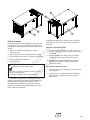
DO NOT lift or move generator without assistance.•
Use lifting pipes as described in • Lifting the Generator.
The unit may shift on the lifting pipes during movement,
which can cause injury.
DO NOT lift unit by roof as damage to generator •
will occur.
WARNING Contact with muffler area can result in
serious burns.
Exhaust heat/gases can ignite combustibles
or structures causing a fire.
DO NOT touch hot parts and AVOID hot exhaust gases.•
Allow equipment to cool before touching.•
DO NOT install the generator closer than 5 feet (1.5m) •
from any combustibles or structures with combustible
walls having a fire resistance rating of less than 1 hour.
Keep at least minimum distances shown in • General
Location Guidelines to insure for proper generator cooling
and maintenance clearances.
It is a violation of California Public Resource Code, •
Section 4442, to use or operate the engine on any forest-
covered, brush-covered, or grass-covered land unless
the exhaust system is equipped with a spark arrester, as
defined in Section 4442, maintained in effective working
order. Other states or federal jurisdictions may have
similar laws.
Contact the original equipment manufacturer, retailer, or
dealer to obtain a spark arrester designed for the exhaust
system installed on this engine.
Replacement parts must be the same and installed in the •
same position as the original parts.
Not for
Reproduction

6 BRIGGSandSTRATTON.COM
CAUTION Installing the 15A fuse could cause the
engine to start.
Observe that the 15 Amp fuse has been removed from the •
control panel for shipping.
DO NOT install this fuse until all plumbing and wiring has •
been completed and inspected.
CAUTION Excessively high operating speeds increase
risk of injury and damage to generator.
Excessively low speeds impose a heavy load on generator.
DO NOT tamper with governed speed. Generator supplies •
correct rated frequency and voltage when running at
governed speed.
DO NOT modify generator in any way.•
NOTICE Improper treatment of generator can damage it
and shorten its life.
Use generator only for intended uses.•
If you have questions about intended use, contact your •
authorized dealer.
Operate generator only on level surfaces.•
Adequate, unobstructed flow of cooling and ventilating air •
is critical to correct generator operation.
The access panels/doors must be installed whenever the •
unit is running.
DO NOT expose generator to excessive moisture, dust, •
dirt, or corrosive vapors.
Remain alert at all times while working on this equipment. •
Never work on the equipment when you are physically
or mentally fatigued.
DO NOT start engine with air cleaner or air cleaner •
cover removed.
DO NOT insert any objects through cooling slots.•
DO NOT use the generator or any of its parts as a step. •
Stepping on the unit can cause stress and break parts.
This may result in dangerous operating conditions from
leaking exhaust gases, fuel leakage, oil leakage, etc.
If connected devices overheat, turn them off and •
disconnect them from generator.
Shut off generator if •
- electrical output is lost;
- equipment sparks, smokes, or emits flames;
- unit vibrates excessively.
NOTICE Exceeding generators wattage/amperage capacity
can damage generator and/or electrical devices connected
to it.
See • Essential Circuits in operator’s manual.
Start generator and let engine stabilize before connecting •
electrical loads.
WARNING Moving parts can crush and cut.
Starter and other rotating parts
can entangle hands, hair, clothing,
or accessories.
NEVER operate generator without protective housings, •
covers, or guards in place.
DO NOT wear loose clothing, jewelry or anything that may •
be caught in the starter or other rotating parts.
Tie up long hair and remove jewelry.•
Before servicing, remove 15 Amp fuse from control panel •
and disconnect Negative (NEG or ‑) battery cable.
WARNING Hot pressurized coolant can cause severe
injury and/or property damage.
DO NOT open radiator cap when hot.•
Before servicing, allow coolant to cool.•
Not for
Reproduction

7
Installation
We sincerely appreciate your patronage. For this reason, we
have made every effort to provide for a safe, streamlined
and cost-effective installation. Because each installation is
unique, it is impossible to know of and advise the trade of all
conceivable procedures and methods by which installation
might be achieved. Neither could we know of possible
hazards and/or the results of each method or procedure.
For these reasons, only current licensed electrical
and plumbing professionals should attempt home
generator system installations. Installations must strictly
comply with all applicable codes, industry standards
and regulations.
Your home generator is supplied with this “Operator’s
Manual” and a separate “Installation Manual”. These are
important documents and should be retained by the owner
after the installation has been completed.
For the Home Owner:
To help you make informed choices and communicate
effectively with your installation contractor(s),
Read and understand Owner Orientation in this
manual before contracting or starting your home
generator installation.
To arrange for proper installation, contact the store at which
you purchased your home generator, your dealer, a licensed
electrician or your utility power provider.
The home generator warranty is VOID unless the
system is installed by licensed electrical and
plumbing professionals.
Every effort has been made to ensure that information in this
manual is accurate and current. However, we reserve the
right to change, alter, or otherwise improve the product and
this document at any time without prior notice.
The Emission Control System for this generator is warranted
for standards set by the U.S. Environmental Protection
Agency and by the California Air Resources Board (CARB).
For the Installing Dealer/Contractor:
For most applications, the Installation manual contains
all the information required to properly install and start
the home generator. This operator’s manual describes
essential circuit selection, routine operation and owner
maintenance procedures.
If you need more information in this matter, please call
(800) 743‑4115, between 8:00 AM and 5:00 PM CT.
Owner Orientation
This section provides home generator owners with the
information necessary to achieve the most satisfactory and
cost effective installation possible.
The illustrations are for typical circumstances and are meant
to familiarize you with the installation options available with
your home generator. A thorough understanding of these
options will provide fundamental control over the cost of
your installation, as well as ensure your final satisfaction
and security.
Federal and local codes, appearance, noise levels, fuel types,
and distances are the factors that must be considered when
negotiating with an installation professional. Remember
that as the distance from the existing electrical service and
gaseous fuel supply increases, and the number of 90 degree
bends in the fuel supply increases, compensations in piping
and wiring materials must be made. This is necessary to
comply with local codes and overcome electrical voltage
drops and gaseous fuel pressure drops.
The factors mentioned above will have a direct affect on
the overall price of your home generator installation.
In some areas you may need to acquire electrical permits for
installing the home generator, building permits for installing
gas lines, and permits for noise allowances. Your installer
should check your local codes AND obtain the permits before
installing the system.
Fuel Factors
An important consideration affecting the entire installation is
the type of fuel used by your home generator. The system
was factory tested and adjusted using either natural gas
or liquid propane (LP vapor). For proper engine function,
factors that are inherent to each of these fuels, your
location and the duration of possible utility interruptions are
important considerations in the following fuel guidelines:
• Useclean,dryfuel,freeofmoistureorany
particulate material. Using fuels outside the
following recommended values may cause
performance problems.
• Inenginessetuptorunonpropane(LP),commercial
grade HD5 propane with a minimum fuel energy of
2500 BTUs/ft3 with maximum propylene content of
5% and butane and heavier gas content of 2.5% and
minimum propane content of 90%.
Natural gas rating will depend on specific fuel but typical
derates are between 10 to 20% off the LP gas rating.
WARNING Propane and Natural Gas are extremely
flammable and explosive.
Fire or explosion can cause severe burns
or death.
The home generator is equipped with an automatic safety •
gas “fuel shut-off” valve.
DO NOT operate the equipment if the “fuel shut-off” valve •
is missing or inoperative.
Not for
Reproduction

8 BRIGGSandSTRATTON.COM
Power Decrease at High Altitude or High Temperature
Air density is less at high altitudes, resulting in less available
engine power. Specifically, engine power will decrease 3.5%
for each 1,000 feet (300 meters) above sea level and 1% for
each 10° F (5.6°C) above 77°F (25°C). Make sure you and
your installer consider these factors when determining total
generator load.
Generator Location
The actual physical location of your home generator has a
direct affect on:
1. The amount of plumbing required to fuel
your generator.
2. The amount of wiring required to control and connect
your generator.
Specific location guidelines are discussed in the installation
manual. Acquaint yourself with that information and confer
with your installer. Be sure to ask how your site might
affect installation costs and compliance with local codes
and standards.
The generator must be installed outdoors. DO NOT install
generator where exhaust gas could accumulate and enter
inside or be drawn into a potentially occupied building.
Ensure exhaust gas is kept away from any windows, doors,
ventilation intakes or other openings that can allow exhaust
gas to collect in a confined area. Prevailing winds and air
currents should be taken into consideration when positioning
generator. See the installation manual for full details on safe
generator location.
Essential Circuits
As a home generator owner, it is important that you clearly
identify the circuits in your building that are “essential” to
you. Your installer will then know which circuits you want
to include as “Essential Circuits”. Depending on the power
consumed by these circuits, most or all of them can be
switched to the home generator for the duration of normal
power interruption.
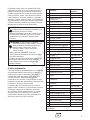
The wattage reference table that follows will assist you with
your decision-making process. It provides the wattage used
by many ordinary household devices. Use it when selecting
your essential circuits. Review this information with your
installer and ask about any technical considerations that
might affect your installation. This chart serves as a guide
only. For exact wattage use an appropriate wattage meter.
WARNING Running engine gives off carbon monoxide,
an odorless, colorless, poison gas.
Breathing carbon monoxide can cause headache,
fatigue, dizziness, vomiting, confusion, seizures,
nausea, fainting or death.
Operate generator ONLY outdoors.•
Install a battery operated carbon monoxide alarm near •
the bedrooms.
Keep exhaust gas from entering a confined area through •
windows, doors, ventilation intakes, or other openings.
WARNING Exhaust heat/gases can ignite combustibles
or structures causing a fire.
DO NOT install the generator closer than 5 feet (1.5m) •
from any combustibles or structures with combustible
walls having a fire resistance rating of less than 1 hour.
Not for
Reproduction

9
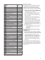
Device
Running
Watts
Air Conditioner (12,000 Btu)* 1700
Air Conditioner (24,000 Btu)* 3800
Air Conditioner (40,000 Btu)* 6000
Battery Charger (20 Amp) 500
Circular Saw (6-1/2”) 800 to 1000
Clothes Dryer (Electric)* 5750
Clothes Dryer (Gas)* 700
Clothes Washer* 1150
Coffee Maker 1750
Compressor (1 HP)* 2000
Compressor (1/2 HP)* 1400
Curling Iron 700
Dehumidifier* 650
Electric Blanket 400
Electric Range (per element) 1500
Electric Skillet 1250
Freezer* 700
Furnace Fan (1/2 HP)* 800
Garage Door Opener* 500 to 750
Hair Dryer 1200
Hand Drill 250 to 1100
Iron 1200
Jet Pump* 800
Light Bulb 100
Microwave Oven 700 to 1000
Milk Cooler* 1100
Oil Burner on Furnace 300
Oil Fired Space Heater (140,000 Btu) 400
Oil Fired Space Heater (30,000 Btu) 150
Oil Fired Space Heater (85,000 Btu) 225
Radio 50 to 200
Refrigerator 700
Slow Cooker 200
Submersible Pump (1 HP)* 2000
Submersible Pump (1/2 HP)* 1500
Submersible Pump (1-1/2 HP)* 2800
Sump Pump* 800 to 1050
Table Saw (10”)* 1750 to 2000
Television 200 to 500
Toaster 1000 to 1650
*Allow three (3) times listed watts for starting device
Essential Circuit Selection
When selecting the essential circuits that will be switched
to “Standby Power,” it is important that the sum of the
combined circuit loads does not exceed the wattage/
amperage capacity of the generator. To help you with your
selection of essential circuits, please consider the following:
• Addupthetotalwattageofallelectricaldevicestobe
connected at one time. This total should NOT be greater
than the generator’s wattage capacity.
The rated wattage of lights can be taken from light
bulbs. The rated wattage of tools, appliances and
motors can usually be found on a data plate or label
affixed to the device.
• Iftheappliance,toolormotornameplatedoesnot
list wattage, multiply volts times the ampere rating to
determine watts (Volts x Amps = Watts).
Some electric motors (induction types) require about
three times more watts of power for starting than for
running. This surge lasts for only a few seconds. Be
sure you allow for this high starting wattage when
selecting electrical devices that will be energized by the
home generator:
• Figurethewattsrequiredtostartthelargestmotor.
• Addthattothetotalrunningwattsofallother
connected loads.
This generator complies with the following “stationary
standby power rating”:
The standby power rating is applicable for supplying
power for the duration of normal power interruption. No
sustained overload capability is available for this rating.
This rating is applicable to installations served by
a reliable normal utility source. This rating is only
applicable to variable loads with an average load factor
of 80% of the standby rating. The standby rating is
only applicable for optional standby power where
the generator set serves as the backup to the normal
utility source.
Use the wattage reference table provided and mark those
circuits you consider “critical” or “essential”. Make sure you
and your installer consider the system’s altitude above sea
level and the ambient temperature range when determining
total generator load.
Not for
Reproduction

10 BRIGGSandSTRATTON.COM
In a utility outage, you need to ‘manage’ power distribution
by turning off non-essential loads. Some examples of non
essential loads are as follows:
• Poolpump
• Hottub
• Electrichottuband/orpoolheaters
• Centralairconditioners
• Electrichotwaterheaters
• Electricrangeand/oroven
• Arcwelder
• Nonessentialelectricheaters
Delivery Inspection
Carefully inspect the home generator for any damage that
may have occurred during shipment.
If loss or damage is noted at time of delivery, have the
person(s) making delivery note all damage on the freight
bill and affix his signature under the consignor’s memo of
loss or damage. If loss or damage is noted after delivery,
separate the damaged materials and contact the carrier and
your installer for claim procedures. Missing or damaged
parts are not warranted.
The home generator is supplied with:
• Fully-servicedcoolantsystem
• Fully-servicedoil/lubricatingsystem
• Flexiblefuelhook-uphose
• Installationandstart-upmanual
• Operator’smanual
• Engineoperator’smanual
• Installationchecklist
• Spareaccessdoorkeys
• Spare15Afuse
• Tenpinconnector(forsensingandcontrolwires)
• Touchuppaint
• RemoteLEDindicatorkit(LED/plate/screws)
To be supplied by installer:
• Startingbattery
• Reinforcedconcretemountingpad
• Connectingwireandconduit
• Fuelsupplyvalves/plumbing
• Variousspecialtytools/equipment
Not for
Reproduction

11
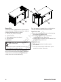
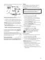
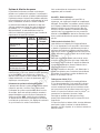
Controls
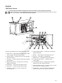
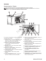
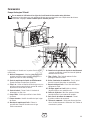
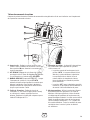
30 kW Home Generator
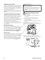
Read this Operator’s Manual and Important Safety Instructions before operating your generator.
Compare the illustrations of this 30kW model with your generator to familiarize yourself with the locations of various
controls and adjustments. Save this manual for future reference.
A
D
E F
H
J
N
R
P
L
K
G
C
B
M
Generator is pictured with access doors removed for clarity
A - Exhaust Port — High-performance muffler lowers engine
noise to comply with most residential codes.
B - Coolant Fill Door — Provides access for servicing engine
with oil and coolant.
C - Air Cleaner — Protects engine by filtering dust and debris
out of intake air.
D - Battery Door opening — Provides access to starting
battery and air cleaner.
E - Oil Dip Stick — Used to check the engine oil level.
F - Engine Label — Identifies engine model and type.
G - Oil Fill Cap — Remove to service the engine with
recommended oil.
H - Coolant Recovery Bottle — Provides visual indicator of
engine coolant level.
J - Oil Filter — Filters engine oil to prolong system life.
K - Fuel Inlet — Fuel supply is connected here.
L - Oil Drain Hose — Provided to facilitate oil changing.
M - ID Label (located on base) — Identifies unit by
serial number.
N - Circuit Breaker Enclosure - Equipped with removable
bottom to assist with conduit connection.
P - Control Panel Door opening — Provides access to control
panel, oil filter, etc. (may be two doors)
R - Control Panel — Used for various test, operation and
maintenance functions. See System Control Panel.
Not for
Reproduction

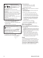
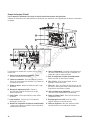
12 BRIGGSandSTRATTON.COM
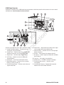
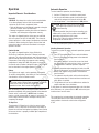
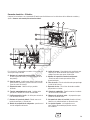
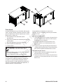
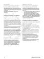
Generator is pictured with access doors removed for clarity
A - Control Panel Door opening — Provides access to
control panel (may be two doors).
B - Control Panel — Used for various test, operation and
maintenance functions. See System Control Panel.
C - Engine Label — Identifies engine model and type.
D - Oil Fill Cap — Remove to service the engine with
recommended oil.
E - Oil Dip Stick — Used to check the engine oil level.
F - Battery Door opening — Provides access to starting
battery, air cleaner, oil filter, etc.
G - Coolant Recovery Bottle — Provides visual indicator of
engine coolant level.
H - Exhaust Port — High-performance muffler lowers engine
noise to comply with most residential codes.
J - Coolant Fill Door — Provides access for servicing engine
with oil and coolant.
K - Oil Filter — Filters engine oil to prolong system life.
L - Air Cleaner — Protects engine by filtering dust and debris
out of intake air.
M - Fuel Inlet — Fuel supply is connected here.
N - Oil Drain Hose — Provided to facilitate oil changing.
P - ID Label (located on base) — Identifies unit by
serial number.
R - Circuit Breaker Enclosure - Equipped with removable
bottom to assist with conduit connection.
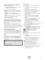
45 kW Home Generator
Compare the illustrations of this 45kW model with your generator to familiarize yourself with the locations of various controls
and adjustments. Save this manual for future reference.
B
H
J L
K
G
F
DC
MNR P
A
E
Not for
Reproduction

13
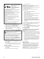
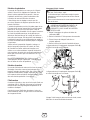
System Control Panel
Compare this Control Panel illustration with your generator to familiarize yourself with the location of these important controls:
A - Circuit Breaker — Protects the system from shorts and
other over-current conditions. Must be ON to supply
power to the automatic transfer switch.
B – SET EXERCISE— Used to set the exercise cycle start
time. Exercise cycle only occurs in AUTO mode.
C – MANUAL OVER‑RIDE— With system switch in AUTO
position, push the manual over-ride button for six
seconds to start the generator. To turn off the generator,
push and hold the manual over-ride button until
engine stops.
D - 15 Amp Fuse — Protects the system DC control circuits.
If the fuse has ‘blown’ (melted open) or was removed,
the engine cannot crank or start. Replace the fuse using
only an identical ATO 15A fuse.
E - System Switch — This two-position switch is the most
important control on the system and is used as follows:
•“AUTO” position is the normal operating position. If a
utility power outage is sensed, the system will start the
generator. When utility power is restored, AUTO lets
the engine stabilize internal temperatures, shuts off the
generator, and waits for the next utility power outage.
•“OFF” position turns off running generator, prevents
unit from starting and resets any detected faults.
F - Digital Display — Displays the total number of hours
the generator has been running and fault codes. Used
to schedule maintenance tasks and for troubleshooting
operational problems with the home generator. A
constant number displayed indicates the total hours of
operation. Fault conditions will flash “FC” followed by a
fault code number. All fault conditions are described in
Fault Detection System.
B
A
C
D
FE
Not for
Reproduction

14 BRIGGSandSTRATTON.COM
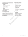
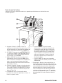
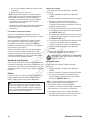
Access Ports
The home generator is equipped with an enclosure that has
several access doors. The doors are named for a significant
component located behind them, as follows::
A - Fuel Inlet port (shown for reference)
B - Control Panel door
C - Exhaust opening (shown for reference)
D - Coolant Fill door
E - Battery door
The enclosure also includes muffler and radiator access
panels, used for cleaning those components. Those panels
should remain closed at all other times to assure proper
cooling, reduce noise, and for added safety.
Each home generator is supplied with a set of identical keys.
These keys fit the locks that secure the access doors.
To open access door:
1. Insert key into lock of access door handle and turn key
one quarter turn counterclockwise.
2. Grasp door’s handle and turn one quarter turn
counterclockwise to open. Remove key.
3. Coolant Fill door is unlocked in the same manner. It can
be used for adding coolant or oil.
To close access door:
1. Close door and turn door’s handle one quarter
turn clockwise.
2. Insert key into lock of door handle and turn key one
quarter turn clockwise. Remove key.
B
A
C
D
E
WARNING Contact with muffler and engine parts can
result in serious burns.
DO NOT touch hot parts and AVOID hot exhaust gases.•
Allow equipment to cool before touching.•
Not for
Reproduction

15
Operation
Important Owner’s Considerations
Engine Oil
This engine is shipped from the factory pre-run and filled
with non-synthetic oil (API SL 10W-30W). This allows for
system operation in a wide range of temperature and climate
conditions. Before starting the engine, check oil level and
ensure that engine is serviced as described in the engine
operator’s manual.
Coolant System
This engine is shipped from the factory filled with a
50-50 mix of automotive (Dex-Cool™ orange) anti-freeze
and water. This will provide optimum year round protection
against freezing, boiling and corrosion. The coolant system
incorporates a water heater that operates when ambient
temperature is below 80ºF AND utility power is present at
the transfer switch. Before starting the engine, check coolant
level as described in the engine operator’s manual.
Battery
The installer must supply a valve-regulated, rechargeable
12 volt DC starting battery. See Battery in Final Installation
Considerations in the installation manual.
With the battery installed, all wiring to transfer switch and
generator completed, utility power supplied to the automatic
transfer switch, and the unit in AUTO mode, the battery
receives a trickle charge while the engine is not running. The
trickle charge cannot be used to recharge a battery that is
completely discharged.
15 Amp Fuse
The generator’s 15 Amp fuse is critical to correct system
operation. The 15 Amp fuse was removed at the factory to
prevent the unit from starting during shipping. Your installer
will ensure the fuse is properly installed upon completion of
the installation.
Automatic Operation
To select automatic operation, do the following:
1. Confirm 15 Amp fuse is installed in control panel.
2. Set the main distribution panel circuit breaker that
sends utility voltage to the transfer switch to ON.
3. Set the generator’s circuit breaker to its ON position.
4. Set the control panel system switch to AUTO.
Checking Automatic Operation
To check the system for proper automatic operation, proceed
as follows:
1. Turn OFF the service disconnect or main distribution
panel circuit breaker sending power to the automatic
transfer switch.
When utility voltage is lost and the sensor has timed
out, the engine will crank and start. Let the system go
through its entire automatic operation sequence.
2. With the generator output supplying its loads, turn ON
the service disconnect or main distribution panel circuit
breaker that supplies utility power to the automatic
transfer switch.
3. The automatic transfer switch will transfer loads back
to utility power after a 5 minute minimum run time and
utility power is available.
4. The generator will run for an additional one minute for
engine cool down, then shut down.
If utility power is restored and generator does not shut down
after 10 minutes, set system switch to OFF and contact your
installer or local service center.
This completes the test procedures for automatic operation.
The home generator will now start automatically and will
supply power to the transfer switch when utility power
is lost.
WARNING Battery posts, terminals and related
accessories contain lead and lead compounds - chemicals
known to the State of California to cause cancer and
reproductive harm. Wash hands after handling.
NOTICE Any attempt to crank or start the engine before
it has been properly serviced with the recommended
coolant or oil will result in equipment failure.
Refer to • Maintenance in the operator’s manual and engine
manual for coolant and oil fill information.
Damage to equipment resulting from failure to follow this •
instruction will void engine and generator warranty.
CAUTION With the system switch set to AUTO,
the engine may crank and start at any time
without warning.
To prevent possible injury that may be caused by such •
sudden starts, always set the system switch to OFF if
performing maintenance on the system.
Remove the 15 Amp fuse before working on or around •
the generator or transfer switch.
Not for
Reproduction

16 BRIGGSandSTRATTON.COM
Setting Exercise Timer
The home generator is equipped with an exercise timer that
will start and exercise the system once every seven days.
During this exercise period, the unit runs for approximately
20 minutes and then shuts down. Electrical load transfer
DOES NOT occur during the exercise cycle (unless an utility
power outage occurs).
A button on the control panel is labeled “SET EXERCISE”
(see System Control Panel). The specific day and the
specific time of day this button is pressed is programmed
into the control board memory. This date and time is then
used to automatically initiate the system exercise cycle. The
“SET EXERCISE” legend on the control panel will flash until
the set exercise cycle is set.
To perform the Set Exercise procedure:
1. Choose the day and time you want your home
generator to exercise.
2. On that day and time, press and hold “SET EXERCISE”
for three seconds.
“SET EXERCISE” will flash until the button is pressed
for three seconds, then “SET EXERCISE” will illuminate
for 5 seconds, and finally turn off.
3. The unit will then start and run it’s 20 minute
exercise cycle.
For example, if you press SET EXERCISE on Sunday morning
at 10:00 AM, the unit will run an immediate exercise cycle
and an exercise cycle every following Sunday at 10:00 AM
(+/- 1/2 hour).
“Set Exercise” will only work if the unit is in the AUTO mode
and this exact procedure is followed. The exerciser will need
to be re-set if the 15 Amp fuse is removed or changed, or if
the starting battery is disconnected.
If you want to change the day and time the unit exercises,
simply perform the “Set Exercise” procedure at the exact
weekday and time you want it to take place.
Maintenance
Servicing the System
Before performing any generator maintenance, always
perform the following steps:
1. Set generator’s circuit breaker to its OFF position.
2. Set control panel system switch to OFF.
3. Remove 15 Amp fuse from control panel.
4. Utility voltage is present at generator control panel.
Disconnect power before servicing control panel by
removing the fuses from the transfer switch.
5. After all servicing has been completed, replace fuses in
transfer switch, replace 15 Amp fuse in control panel,
set system switch and circuit breaker ON and reset
exercise timer. See Setting Exercise Timer.
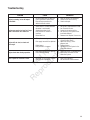
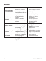
Fault Detection System
The generator may have to run for long periods of time
with no operator present. For that reason, the system is
equipped with sensors that automatically shut down the
generator in the event of potentially damaging conditions,
such as low oil pressure, high temperature, over speed, and
other conditions.
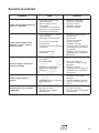
The generator’s control panel has a digital display that shows
fault codes, like “FC_1”. The table below lists the detected
fault, the fault code as displayed on the control panel, and
the number of LED flashes (also described as ‘blinks’) seen
on the remote LED indicator.
Fault Description Fault Codes LED Flashes
Low battery voltage FC_1 1
Low oil pressure FC_2 2
Low voltage FC_3 3
Engine fails to start FC_4 4
Low frequency FC_5 5
Engine overspeed FC_6 6
High temperature FC_7 7
Transfer switch fault FC_8 8
The remote LED indicator is installed at a convenient inside
location. The LED will remain lit when the generator is in
AUTO. Should a system fault be detected, the LED will turn
on and off in a series of blinks that identify the problem. The
blink pattern is repeated with a brief pause between each
series of blinks.
Not for
Reproduction

17
Reset Fault Detection System
The operator must reset the fault detection system each
time it activates. To do so, place the control panel system
switch in the OFF position for 30 seconds or more. Remedy
the fault condition, then return the generator to service by
installing the 15 Amp fuse, placing the system switch in the
AUTO position, and resetting the exercise timer. See Setting
Exercise Timer in Operation.
A description of each fault and suggested remedies are
as follows:
No LED ‑ Discharged Battery
If there is a detected fault condition but the LED is
not blinking, this is because the battery is completely
discharged. To remedy the problem, remove the 15 Amp
fuse and disconnect the battery from the generator. Take
the battery to a local battery store for analysis. Reinstall
battery after it has been fully recharged, connecting the
NEGATIVE cable last. Then reset the fault detection system,
as described earlier.
Low Battery Voltage (FC_1)
This fault is indicated by fault code FC_1 and one blink on
the LED indicator. This condition occurs if the generator
cannot start because the starting battery output power is
below that needed to crank the engine. Causes for this
problem may be a faulty battery or battery charge circuit.
To remedy the problem, contact your local service center to
check the battery charge output. Remove the 15 Amp fuse
and disconnect the battery from the generator. Take the
battery to a local battery store for analysis.
Reinstall the battery (replace if necessary - see Battery in
Final Installation Considerations in the installation manual).
Then reset the fault detection system, as described earlier.
Low Oil Pressure (FC_2)
This fault is indicated by fault code FC_2 and two blinks on
the remote LED indicator. The unit is equipped with an oil
pressure switch that uses normally closed contacts held
open by engine oil pressure during operation. Should oil
pressure drop below the 8 psi range, switch contacts close
and the engine is shut down.
To remedy the low oil pressure condition, add the
recommended oil to the FULL mark on the dipstick.
If the low oil pressure condition still exists, the engine will
start, then shut down again. The fault code will appear and
the LED will flash. In this case, contact an authorized dealer.
Low Voltage (Generator, FC_3)
This fault is indicated by fault code FC_3 and three blinks on
the LED indicator. This condition is caused by a restriction in
the fuel flow, a broken or disconnected signal lead, a failed
alternator winding, the control panel circuit breaker is open,
or the generator is overloaded.
To remedy the problem, contact your installer or an
authorized dealer.
Engine Fail To Start (FC_4)
This fault is indicated by fault code FC_4 and four blinks
on the LED indicator. This feature prevents the generator
from damaging itself if it continually attempts to start in
spite of another problem, such as no fuel supply. Each
time the system is directed to start, the unit will crank for
10 seconds, pause for 10 seconds, and repeat. If the system
does not begin producing electricity after approximately
2 minutes, the unit will stop cranking and the LED will blink.
Check to make sure the generator’s circuit breaker is in the
ON position in order for the sensing leads to verify that the
unit is running.
The most likely cause of this problem is no fuel supply.
Check the internal and external fuel shut off valves to
ensure they are fully open. Other causes could be failed
spark plug(s), failed engine ignition, or the engine air filter
is clogged. You may need to contact your installer for
assistance if you can’t remedy these problems.
Low Frequency (FC_5)
This fault is indicated by fault code FC_5 and five blinks on
the LED indicator. This feature protects devices connected
to the transfer switch by shutting the generator down if the
engine runs slower than 55 Hz for three seconds.
This condition is caused by a failed engine component or by
excessive loads on the generator. To remedy the problem,
contact your installer or an authorized dealer.
Engine Overspeed (FC_6)
This fault is indicated by fault code FC_6 and six blinks on
the LED indicator. This feature protects devices connected
to the transfer switch by shutting the generator down if
the engine happens to run faster than the preset limit. The
overspeed fault is detected as follows:
•Ifthegeneratoroutputfrequencyis65-70Hz,afterthree
seconds, the generator will shut down.
•Ifthegeneratoroutputfrequencyisgreaterthan70Hz,
the generator will shut down immediately.
This condition is caused by a failed engine component.
To remedy the problem, contact your installer or an
authorized dealer.
Not for
Reproduction

18 BRIGGSandSTRATTON.COM
High Temperature (FC_7)
This fault is indicated by fault code FC_7 and seven blinks
on the LED indicator. The contacts of the temperature
switch are normally open. If the engine temperature exceeds
approximately 115°C (240°F), the fault is detected and the
engine shuts down.
Common causes for this condition include running the
unit with all access doors removed, obstructed air inlet or
exhaust port, low oil or coolant level, or debris in the engine
compartment or radiator.
To resolve the problem, let the engine cool down and remove
any accumulated debris and obstructions. Ensure that all
access doors are installed whenever the unit is running.
Transfer Switch Fault (FC_8)
This fault is indicated by fault code FC_8 and eight blinks
on the LED indicator (if transfer switch is equipped with
fault detection).
The most likely cause of this fault is a blown fuse in the
transfer switch. To remedy the problem, contact your
installer or an authorized dealer.
Generator Maintenance
The generator warranty does not cover items that have been
subjected to operator abuse or neglect. To receive full value
from the warranty, the operator must maintain the system as
instructed in the engine operator’s manual.
All adjustments should be made at least once each season.
Follow the requirements in the engine operator’s manual.
Generator maintenance consists of keeping the unit
clean. Operate the unit in an environment where it will
not be exposed to excessive dust, dirt, moisture or any
corrosive vapors. Cooling air louvers on the enclosure
must not become clogged with snow, leaves, or any other
foreign material. To prevent generator damage caused by
overheating, keep the enclosure cooling inlets and outlets
clean and unobstructed at all times.
Check the cleanliness of the unit frequently and clean when
dust, dirt, oil, moisture or other foreign substances are
visible on its exterior/interior surface. Inspect the air inlet
and outlet openings inside and outside the enclosure to
ensure air flow is not blocked.
DO NOT use direct spray from a garden hose to clean
generator. Water can enter the engine and generator and
cause problems.
Engine Maintenance
An engine manual was packaged with this system. Refer to
that manual for all engine-related maintenance topics, such
as oil, oil filter, air cleaner, coolant, spark plugs and so forth.
Proper engine cooling and lubrication are very important, so
pay particular attention to these matters.
Engine Oil
The engine is shipped from the factory pre-run and filled
with non-synthetic oil (API SL 10W-30). This allows for
system operation in a wide range of temperature and
climate conditions.
Refer to the engine operator’s manual for recommended oil
change intervals.
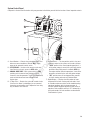
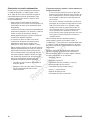
Changing Engine Oil
KEEP OUT OF REACH OF CHILDREN. DON’T
POLLUTE. CONSERVE RESOURCES. RETURN
USED OIL TO COLLECTION CENTERS.
1. Set control board system switch to OFF.
2. Remove 15 Amp fuse from control panel.
3. Place oil drain hose into an approved container.
4. Remove brass fitting from end of drain hose.
Shown here is the oil drain hose (B) and the oil filter location
(A) for the 30kW generator:
A
B
CAUTION Avoid prolonged or repeated skin contact
with used motor oil.
Used motor oil has been shown to cause skin cancer in •
certain laboratory animals.
Thoroughly wash exposed areas with soap and water.•
Not for
Reproduction

19
Shown here is the oil drain hose (B) and the oil filter location
(A) for the 45kW generator:
Change oil while the engine is still warm from running, as
described in the engine operator’s manual.
5. When oil has drained, replace brass fitting on hose.
6. Add oil. Follow the oil grade recommendation and oil fill
instructions given in the engine operator’s manual.
If all engine servicing is complete, replace 15 Amp fuse in
control panel and reset exercise timer. See Setting Exercise
Timer in Operation.
To make the task of adding oil more convenient, we
recommend use of a funnel attached to a length of tubing
long enough to reach from the Coolant Fill door to the oil fill
opening on the engine valve cover.
Engine Coolant System
With the engine cold, check the coolant level in the coolant
recovery bottle (see Controls). Maintenance instructions for
engine coolant are found in the engine operator’s manual.
Battery
Servicing of batteries is to be performed or supervised
by personnel knowledgeable of batteries and the
required precautions. Keep unauthorized personnel away
from batteries.
Servicing the Battery
If it is necessary to service the battery, proceed as follows:
1. Set control board system switch to OFF.
2. Remove 15 Amp fuse from control panel.
3. Service or replace battery as required. See Battery
in Final Installation Considerations in the installation
manual for specific battery needed.
4. Connect red battery cable to battery positive terminal
(indicated by POSITIVE, POS, or (+)).
5. Connect black battery cable to negative battery terminal
(indicated by NEGATIVE, NEG, or (‑)).
6. Ensure hardware on both positive and negative battery
terminals is secure.
7. Reinstall 15 Amp fuse in control panel.
8. Set generator’s system switch to AUTO.
9. Reset exercise timer. See Setting Exercise Timer.
DON’T POLLUTE. CONSERVE RESOURCES,
RETURN USED BATTERY TO RECYCLING
COLLECTION CENTER.
Charging the Battery
If it is necessary to charge the battery, proceed as follows:
1. Set control board system switch to OFF.
2. Remove 15 Amp fuse from control panel.
3. Disconnect negative battery cable from negative battery
terminal (indicated by NEGATIVE, NEG, or (‑)).
4. Charge battery with battery charger at 2 Amps until
battery holds 12 Volts. DO NOT exceed 13.7 volts when
charging battery.
A
B
NOTICE Any attempt to crank or start the engine before
it has been properly serviced with the recommended oil
will result in equipment failure.
Refer to • Maintenance in the operator’s manual and engine
manual for oil fill information.
Damage to equipment resulting from failure to follow this •
instruction will void engine and generator warranty.
WARNING Battery posts, terminals and related
accessories contain lead and lead compounds - chemicals
known to the State of California to cause cancer and
reproductive harm. Wash hands after handling.
NOTICE Failure to disconnect negative battery cable will
result in equipment failure.
DO NOT attempt to jump start the generator.•
Damage to equipment resulting from failure to follow this •
instruction will void engine and generator warranty.
Not for
Reproduction

20 BRIGGSandSTRATTON.COM
5. Connect negative battery cable to negative battery
terminal (indicated by NEGATIVE, NEG, or (‑)).
6. Ensure hardware on both positive and negative battery
terminals is secure.
7. Reinstall 15 Amp fuse in control panel.
8. Set generator’s system switch to AUTO.
9. Reset exercise timer. See Setting Exercise Timer.
Cleaning the Generator
1. Set control board system switch to OFF.
2. Remove 15 Amp fuse from control panel.
3. Clean generator as desired.
• Useadampclothtowipeexteriorsurfacesclean.
• Useasoft,bristlebrushtoloosencakedondirt,etc.
• Useavacuumcleanertopickuploosedirtanddebris.
• Uselowpressureair(nottoexceed25psi)toblow
away dirt. Inspect cooling air slots and openings on
the generator. These openings must be kept clean
and unobstructed.
4. Reinstall 15 Amp fuse in control panel.
5. Set generator’s system switch to AUTO.
6. Reset exercise timer. See Setting Exercise Timer.
When Calling for Assistance
You must have the following information at hand if it is
necessary to contact a local service center regarding service
or repair of this unit:
1. Obtain the unit Model Number and Serial Number from
the unit ID label. See Controls for location of the label
or refer to the information recorded on the inside front
cover of the installation manual.
2. Obtain the engine identification numbers from the
engine label. See the engine operator’s manual for
location of this information. Please note that several
different engines are described in the engine manual,
so your engine may vary from that shown.
Storage
The home generator system is designed for long term
service as a backup generator. There is no need to take any
storage precautions. However, if it becomes necessary to
take the system out of service for an extended period, call
Technical Services at (800) 743‑4115, between 8:00 AM
and 5:00 PM CT for specific recommendations. Refer to the
engine operator’s manual for additional information.
WARNING Storage batteries give off explosive
hydrogen gas during recharging.
Slightest spark will ignite hydrogen
and cause explosion.
Battery electrolyte fluid contains
acid and is extremely caustic.
Contact with battery contents will cause severe
chemical burns.
A battery presents a risk of electrical shock and high short
circuit current.
DO NOT dispose of battery in a fire. Recycle battery.•
DO NOT allow any open flame, spark, heat, or lit cigarette •
during and for several minutes after charging a battery.
DO NOT open or mutilate the battery.•
Wear protective goggles, rubber apron, rubber boots and •
rubber gloves.
Remove watches, rings, or other metal objects.•
Use tools having insulated handles.•
CAUTION With the system switch set to AUTO,
the engine may crank and start at any time
without warning.
To prevent possible injury that may be caused by such •
sudden starts, always set the system switch to OFF if
performing maintenance on the system.
Remove the 15 Amp fuse before working on or around •
the generator or transfer switch.
NOTICE Improper treatment of generator can damage it
and shorten its life.
DO NOT expose generator to excessive moisture, dust, •
dirt, or corrosive vapors.
DO NOT insert any objects through cooling slots.•
Not for
Reproduction
La page est en cours de chargement...
La page est en cours de chargement...
La page est en cours de chargement...
La page est en cours de chargement...
La page est en cours de chargement...
La page est en cours de chargement...
La page est en cours de chargement...
La page est en cours de chargement...
La page est en cours de chargement...
La page est en cours de chargement...
La page est en cours de chargement...
La page est en cours de chargement...
La page est en cours de chargement...
La page est en cours de chargement...
La page est en cours de chargement...
La page est en cours de chargement...
La page est en cours de chargement...
La page est en cours de chargement...
La page est en cours de chargement...
La page est en cours de chargement...
La page est en cours de chargement...
La page est en cours de chargement...
La page est en cours de chargement...
La page est en cours de chargement...
La page est en cours de chargement...
La page est en cours de chargement...
La page est en cours de chargement...
La page est en cours de chargement...
La page est en cours de chargement...
La page est en cours de chargement...
La page est en cours de chargement...
La page est en cours de chargement...
La page est en cours de chargement...
La page est en cours de chargement...
La page est en cours de chargement...
La page est en cours de chargement...
La page est en cours de chargement...
La page est en cours de chargement...
La page est en cours de chargement...
La page est en cours de chargement...
La page est en cours de chargement...
La page est en cours de chargement...
La page est en cours de chargement...
La page est en cours de chargement...
La page est en cours de chargement...
La page est en cours de chargement...
La page est en cours de chargement...
La page est en cours de chargement...
La page est en cours de chargement...
La page est en cours de chargement...
La page est en cours de chargement...
La page est en cours de chargement...
La page est en cours de chargement...
La page est en cours de chargement...
La page est en cours de chargement...
La page est en cours de chargement...
-
 1
1
-
 2
2
-
 3
3
-
 4
4
-
 5
5
-
 6
6
-
 7
7
-
 8
8
-
 9
9
-
 10
10
-
 11
11
-
 12
12
-
 13
13
-
 14
14
-
 15
15
-
 16
16
-
 17
17
-
 18
18
-
 19
19
-
 20
20
-
 21
21
-
 22
22
-
 23
23
-
 24
24
-
 25
25
-
 26
26
-
 27
27
-
 28
28
-
 29
29
-
 30
30
-
 31
31
-
 32
32
-
 33
33
-
 34
34
-
 35
35
-
 36
36
-
 37
37
-
 38
38
-
 39
39
-
 40
40
-
 41
41
-
 42
42
-
 43
43
-
 44
44
-
 45
45
-
 46
46
-
 47
47
-
 48
48
-
 49
49
-
 50
50
-
 51
51
-
 52
52
-
 53
53
-
 54
54
-
 55
55
-
 56
56
-
 57
57
-
 58
58
-
 59
59
-
 60
60
-
 61
61
-
 62
62
-
 63
63
-
 64
64
-
 65
65
-
 66
66
-
 67
67
-
 68
68
-
 69
69
-
 70
70
-
 71
71
-
 72
72
-
 73
73
-
 74
74
-
 75
75
-
 76
76


Simplicity 076001- Manuel utilisateur
- Catégorie
- Groupes électrogènes
- Taper
- Manuel utilisateur
- Ce manuel convient également à
dans d''autres langues
- English: Simplicity 076001- User manual
- español: Simplicity 076001- Manual de usuario
Documents connexes
-
Simplicity 076004NG- Manuel utilisateur
-
GE 076004NG- Le manuel du propriétaire
-
-
Simplicity 076071-00 Manuel utilisateur
-
Simplicity OPERATOR'S MANUAL BRIGGS & STRATTON 12/15KW STANDBY MODELS- 040204'10'12'13'29'34-0 Manuel utilisateur
-
Briggs & Stratton 18000 Manuel utilisateur
-
Briggs & Stratton 10000 Watt Manuel utilisateur
-
-
Briggs & Stratton 040298-0 Manuel utilisateur
-