Amana AWO6317SFS AWO6317SFS Installation Instruction EN
- Taper
- AWO6317SFS Installation Instruction EN

INSTALLATION INSTRUCTIONS
27 " (68.6 CM)AND 30" (76.2 CM) ELECTRIC
SINGLE AND DOUBLE BUILT-IN OVEN
INSTRUCTIONS D’INSTALLATION
FOUR ÉLECTRIQUE ENCASTRÉ
27" (68,6 CM) ET 30" (76,2 CM) –
SIMPLE ET DOUBLE
W10351242C
BUILT-IN OVEN SAFETY .......................................................... 1
INSTALLATION REQUIREMENTS .......................................... 2
Tools and Parts .................................................................... 2
Location Requirements ....................................................... 2
Electrical Requirements ....................................................... 5
INSTALLATION INSTRUCTIONS ........................................... 6
Prepare Built-In Oven .......................................................... 6
Remove Oven Door(s) ......................................................... 6
Positioning Oven Feet
for Multiple Cabinet Cutout Heights .................................... 7
Make Electrical Connection ................................................ 10
Install Oven ........................................................................ 12
Complete Installation ......................................................... 14
SÉCURITÉ DU FOUR ENCASTRÉ ...................................... 15
EXIGENCES D’INSTALLATION ........................................... 16
Outillage et pièces ............................................................. 16
Exigences d’emplacement ................................................ 16
Spécications électriques .................................................. 19
INSTRUCTIONS D’INSTALLATION. .................................... 20
Préparation du four encastré ............................................. 20
Dépose de la porte du four ............................................... 20
Positionnement des pieds du four pour des ouvertures
d’encastrement de hauteur différente ................................ 21
Raccordement électrique .................................................. 24
Installation du four .............................................................. 26
Achever l’installation ......................................................... 28
Table of Contents/Table des matières
IMPORTANT:
Save for local electrical inspector’s use.
IMPORTANT :
À conserver pour consultation par l’inspecteur local des installations électriques.
BUILT-IN OVEN SAFETY
You can be killed or seriously injured if you don't immediately
You
can be killed or seriously injured if you don't
follow
All safety messages will tell you what the potential hazard is, tell you how to reduce the chance of injury, and tell you what can
happen if the instructions are not followed.
Your safety and the safety of others are very important.
We have provided many important safety messages in this manual and on your appliance. Always read and obey all safety
messages.
This is the safety alert symbol.
This symbol alerts you to potential hazards that can kill or hurt you and others.
All safety messages will follow the safety alert symbol and either the word “DANGER” or “WARNING.”
These words mean:
follow instructions.
instructions.
DANGER
WARNING

2
INSTALLATION REQUIREMENTS
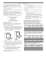
Tools and Parts
Gather the required tools and parts before starting installation.
Read and follow the instructions provided with any tools listed
here.
Tools Needed
■Phillips screwdriver
■Measuring tape
■Hand or electric drill (for wall cabinet installations)
■1" (2.5 cm) drill bit (for wall cabinet installations)
■Level
■Flat-blade screwdriver
Parts Needed
■UL listed or CSA approved conduit connector
■UL listed wire connectors
Parts Supplied
■#8-14 x 1" screws – single ovens (2), double ovens (4)
■Two #8-18 x ³⁄8" screws – bottom vent
■Four #8-18 x ¹⁄4" screws – bottom vent trim
■Four #8-18 x ³⁄8" screws – double oven feet
■Bottom vent
■Bottom vent trim
■Two feet – double oven
■Two front feet – double oven
■Four grommets – single ovens (2), double ovens (4)*
■Foam strip – single oven**
Check local codes. Check existing electrical supply.
See “Electrical Requirements.”
It is recommended that all electrical connections be made
by a licensed, qualified electrical installer.
*Grommets not included with models KEBK171B, KEBK101B,
KEBK276B, KEBK206B, KEBS179B, KEBS109B, KEBS277B,
KEBS279B, KEBS207B, KEBS209B, KEBU109B and
KEBU209B.
**Foam strip not included with double oven.
Location Requirements
IMPORTANT: Observe all governing codes and ordinances.
■Cabinet opening dimensions that are shown must be used.
Given dimensions provide minimum clearance with oven.
■Recessed installation area must provide complete
enclosure around the recessed portion of the oven.
■Grounded electrical supply is required. See “Electrical
Requirements” section.
■Electrical supply junction box should be located 3"
(7.6 cm) maximum below the support surface when the
oven is installed in a wall cabinet. A 1" (2.5 cm) minimum
diameter hole should have been drilled in the right rear or
left rear corner of the support surface to pass the appliance
cable through to the junction box.
NOTE: For undercounter installation, it is recommended
that the junction box be located in the adjacent right or left
cabinet. If you are installing the junction box on rear wall
behind oven, it is recommended that the junction box be
recessed and located in the upper center of the cabinet.
■Oven support surface must be solid, level and ush with
bottom of cabinet cutout.
■Floor must be able to support a single oven weight of
129 lbs (59 kg) for 27" (68.6 cm) models or 154 lbs (70 kg)
for 30" models (76.2 cm).
■Floor must be able to support a double oven weight
of 251 lbs (114 kg) for 27" (68.6 cm) models or 288 lbs
(131 kg) for 30" (76.2 cm) models.
IMPORTANT: To avoid damage to your cabinets, check
with your builder or cabinet supplier to make sure that the
materials used will not discolor, delaminate or sustain other
damage. This oven has been designed in accordance with
the requirements of UL and CSA International and complies
with the maximum allowable wood cabinet temperatures of
194°F (90°C).
Undercounter Installation (with cooktop installed above):
Ovens approved for this type of installation have an approval
label located on the top of the oven. Refer to undercounter
installation instructions for cutout dimensions and approved
oven cooktop combinations (separate sheet).

3
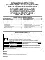
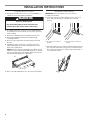
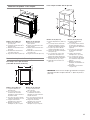
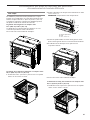
Product Dimensions – Single Ovens
Cabinet Dimensions – Single Oven
Single Oven Undercounter (without cooktop installed above)
27" (68.6 cm) models
A. 28¾" (72.8 cm) max. overall
height
B. 25
7
⁄16" (64.6 cm) max. recessed
width
C. 26³⁄4" (67.9 cm) recessed height
D. 23¹⁄4" (59.1 cm) max. recessed
depth
E. 27" (68.6 cm) overall width
27" (68.6 cm) models
A. 27" (68.6 cm) min. cabinet
width
B. 1¹⁄2" (3.8 cm) min. top of cutout
to underside of countertop
C. 5¹⁄4" (13.3 cm) bottom of cutout
to floor
D. 25¹⁄2" (64.8 cm) cutout width
E. 28" (71.2 cm) min. cutout
height
B
C
D
E
A
A
B
C
D
E
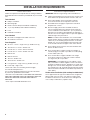
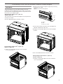
30" (76.2 cm) models
A. 28¾" (72.8 cm) max. overall
height
B. 28½" (72.4 cm) max. recessed
width
C. 26³⁄4" (67.9 cm) recessed height
D. 23¹⁄4" (59.1 cm) max. recessed
depth
E. 30" (76.2 cm) overall width
30" (76.2 cm) models
A. 30" (76.2 cm) min. cabinet
width
B. 1¹⁄2" (3.8 cm) min. top of cutout
to underside of countertop
C. 5¹⁄4" (13.3 cm) bottom of cutout
to floor
D. 28¹⁄2" (72.4 cm) cutout width
E. 28" (71.2 cm) min. cutout
height
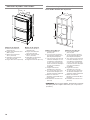
Single Oven Installed in Cabinet
27" (68.6 cm) models
A. 27" (68.6 cm) min. cabinet
width
B. 1" (2.5 cm) top of cutout
to bottom of upper cabinet
door
C. 32" (81.3 cm) bottom of
cutout to floor
D. 25¹⁄2" (64.8 cm) cutout width
E. 1¹⁄2" (3.8 cm) min. bottom of
cutout to top of cabinet door
F. 28" (71.2 cm)* recommended
cutout height
G. 24" (60.7 cm) cutout depth
F
E
B
C
A
D
G
30" (76.2 cm) models
A. 30" (76.2 cm) min. cabinet
width
B. 1" (2.5 cm) top of cutout
to bottom of upper cabinet
door
C. 32" (81.3 cm) bottom of
cutout to floor
D. 28¹⁄2" (72.4 cm) cutout width
E. 1¹⁄2" (3.8 cm) min. bottom of
cutout to top of cabinet door
F. 28" (71.2 cm)* recommended
cutout height
G. 24" (60.7 cm) cutout depth
* NOTE: The cutout height can be between 26
15
⁄16" (68.4 cm)
and 29
7
⁄16" (74.8 cm) for single ovens.

4
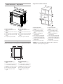
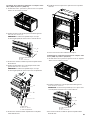
Product Dimensions – Double Ovens
27" (68.6 cm) models
A. 51³⁄16" (130.0 cm) max. overall
height
B. 25
7
⁄16" (64.6 cm) max. recessed
width
C. 48¹³⁄16" (124.0 cm) recessed
height
D. 23¹⁄4" (59.1 cm) max. recessed
depth
E. 27" (68.6 cm) overall width
Cabinet Dimensions – Double Ovens
Double Oven Installed in Cabinet
27" (68.6 cm) models
A. 27" (68.6 cm) min. cabinet
width
B. 1" (2.5 cm) top of cutout to
bottom of upper cabinet door
C. 14³⁄4" (37.5 cm) bottom
of cutout to floor is
recommended. 4"–14³⁄4"
(10.2–37.5 cm) bottom of
cutout to floor is acceptable.
D. 25¹⁄2" (64.8 cm) cutout width
E. 1¹⁄2" (3.8 cm) min. bottom of
cutout to top of cabinet door
F. 50¹⁄4" (127.6 cm)*
recommended cutout height
G. 24" (60.7 cm) cutout depth
C
B
A
E
D
F
E
A
D
G
B
C
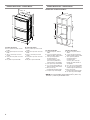
30" (76.2 cm) models
A. 51³⁄16" (130.0 cm) max. overall
height
B. 28½" (72.4 cm) max. recessed
width
C. 48¹³⁄16" (124.0 cm) recessed
height
D. 23¹⁄4" (59.1 cm) max. recessed
depth
E. 30" (76.2 cm) overall width
30" (76.2 cm) models
A. 30" (76.2 cm) min. cabinet
width
B. 1" (2.5 cm) top of cutout to
bottom of upper cabinet door
C. 14³⁄4" (37.5 cm) bottom
of cutout to floor is
recommended.
4"–14³⁄4" (10.2–37.5 cm)
bottom of cutout to floor is
acceptable.
D. 28¹⁄2" (72.4 cm) cutout width
E. 1¹⁄2" (3.8 cm) min. bottom of
cutout to top of cabinet door
F. 50¹⁄4" (127.6 cm)*
recommended cutout height
G. 24" (60.7 cm) cutout depth
* NOTE: The cutout height can be between 48
7
⁄8" (124.1 cm)
and 52³⁄16" (132.6 cm) for double ovens.

5
Electrical Requirements
If codes permit and a separate ground wire is used, it is
recommended that a qualied electrical installer determine
that the ground path and the wire gauge are in accordance
with local codes.
Check with a qualied electrical installer if you are not sure the
oven is properly grounded.
This oven must be connected to a grounded metal, permanent
wiring system.
Be sure that the electrical connection and wire size are
adequate and in conformance with the National Electrical Code,
ANSI/NFPA 70 – latest edition or CSA Standards C22.1-94,
Canadian Electrical Code, Part 1 and C22.2 No. O-M91 – latest
edition, and all local codes and ordinances.
A copy of the above code standards can be obtained from:
National Fire Protection Association
1 Batterymarch Park
Quincy, MA 02169-7471
CSA International
8501 East Pleasant Valley Road
Cleveland, OH 44131-5575
Electrical Connection
To properly install your oven, you must determine the type
of electrical connection you will be using and follow the
instructions provided for it here.
■Oven must be connected to the proper electrical voltage
and frequency as specied on the model/serial number
rating plate. The model/serial number rating plate is located
under the control panel on single ovens and under the
control panel on the upper oven cavity on double ovens.
See the following illustrations.
Single oven
A. Model/serial/rating plate
■Models rated from 7.3 to 9 kW at 240 volts (5.4 to 7.4 kW
at 208 volts) require a separate 40-amp circuit. Models
rated at 4.8 kW and below at 240 volts (3.6 kW and below
at 208 volts) require a separate 20-amp circuit.
■A circuit breaker is recommended.
■Connect directly to the circuit breaker box (or fused
disconnect) through exible, armored or nonmetallic
sheathed, copper cable (with grounding wire).
See “Make Electrical Connection” section.
■Flexible conduit from the oven should be connected
directly to the junction box.
Double oven
A. Model/serial/rating plate
A
A
■ Fuse both sides of the line.
■Do not cut the conduit. The length of conduit provided is
for serviceability of the oven.
■A UL-listed or CSA-approved conduit connector must be
provided.
■If the house has aluminum wiring, follow the procedure
below:
1. Connect a section of solid copper wire to the ends
of the exible conduit leads.
2. Connect the aluminum wiring to the added section
of copper wire using special connectors and/or tools
designed and UL listed for joining copper to aluminum.
Follow the electrical connector manufacturer’s
recommended procedure. Aluminum/copper connection
must conform with local codes and industry accepted
wiring practices.
For power requirements for models WOS51EC7A,
WOS51EC0A, WOD51EC7A, WOD51EC0A, WOS92EC7A,
WOS92EC0A, WOD93EC7A, WOD93EC0A, MEW7527A,
MEW7530A, MEW7627A, MEW7630A, MEW9537A,
MEW9627A, MEW9530A, MEW9630A, IBS300DS, IBS350DS,
IBS550DS, and IBD350DS, refer to the following table.
Voltage Single
Thermal
Single
Convect
Double
Thermal
Double
Convect
240 VAC 3690 W 3720 W 7370 W 7400 W
208 VAC 2790 W 2820 W 5580 W 5610 W
240 VAC 15.4 A 15.5 A 30.7 A 30.8 A
208 VAC 13.4 A 13.6 A 26.8 A 27.0 A
For power requirements for models KEBK171B, KEBK101B,
KEBK276B, KEBK206B, KEBS179B, KEBS109B, KEBS277B,
KEBS279B, KEBS207B and KEBS209B, refer to the following
table.
Voltage Single
Thermal
Single
Convect
Double
Thermal
Double
Convect
240 VAC 4090 W 4120 W 8170 W 8200 W
208 VAC 3099 W 3122 W 6190 W 6212 W
240 VAC 17.1 A 17.2 A 34.1 A 34.2 A
208 VAC 14.9 A 15.0 A 29.8 A 29.9 A
For power requirements for models KEBU109B and
KEBU209B, refer to the following table.
Voltage Single Convect Double Convect
240 VAC 5420 W 9500 W
208 VAC 4106 W 7197 W
240 VAC 22.6 A 39.6 A
208 VAC 19.8 A 34.6 A

6
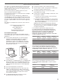
3. Grasp the edges of the oven door with both hands and close
the oven door until it will no longer close. Lift and pull oven
door toward you and remove. Set the oven door(s) aside on
a covered work surface.
INSTALLATION INSTRUCTIONS
Prepare Built-In Oven
1. Decide on the nal location for the oven. Avoid drilling or
cutting into house wiring during installation.
2. To avoid oor damage, set the oven onto cardboard prior
to installation. Do not use handle or any portion of the front
frame for lifting.
3. Remove the shipping materials and tape from the oven.
4. Remove the hardware package from inside the bag
containing literature.
5. Remove and set aside racks and other parts from inside
the oven.
6. If installing a single oven below a cooktop, remove the
adhesive backing from the foam strip and press it to the
back of the control panel.
NOTE: When the cooktop is installed in the cabinet, the top
edge of the foam strip should be approximately ³⁄8" (10 mm)
from the top edge of the control panel. Make sure the foam
strip is positioned against the cabinet face.
7. Move oven and cardboard close to the oven’s nal location.
WARNING
Excessive Weight Hazard
Use two or more people to move and install oven.
Failure to do so can result in back or other injury.
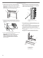
Remove Oven Door(s)
IMPORTANT: Use both hands to remove oven doors.
1. Open the oven door.
2. Locate the oven door latches in both corners of the oven
door, and rotate the latches forward to the unlocked
position.
A. Oven door latch in locked
position
B. Oven door latch in unlocked
position
A. Foam strip
A
B
A

7
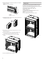
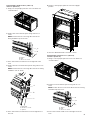
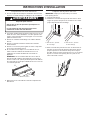
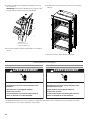
Positioning Oven Feet for Multiple Cabinet Cutout Heights
Single Ovens
The positioning of the oven feet allow a single oven to be
installed in a cutout height between 26
15
⁄16" (68.4 cm) and 29
7
⁄16"
(74.8 cm). Refer to the following instructions to position the feet
for the size of your cabinet cutout.
Cutout height is between 27
5
⁄8" (70.2 cm)
and 28
5
⁄8" (72.7 cm)
The oven feet do not need to be changed. They are positioned
correctly as received.
Go to the “Make Electrical Connection” section.
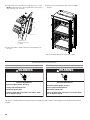
Cutout Height is between 26
15
⁄16" (68.4 cm)
and 27¹¹⁄16" (70.3 cm)
1. Using 2 or more people, place the oven on its back
on a covered surface.
2. Remove the foot from the right front spacer by removing
the #8-18 x ³⁄8" screw.
NOTE: Do not remove the spacer.
A. Spacer
B. Foot
C. #8-18 x ³⁄8" screw
3. In the same manner, remove the feet on the right rear,
left front, and left rear of the oven.
4. Using 2 or more people, place the oven in its upright
position.
5. Go to the “Make Electrical Connection” section.
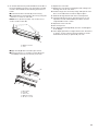
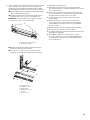
Cutout Height is between 28¹¹⁄16" (72.8 cm)
and 29
7
⁄16" (74.8 cm)
1. Using 2 or more people, place the oven on its back
on a covered surface.
A
B
C

8
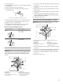
2. Remove the foot from the right front spacer by removing the
#8-18 x ³⁄8" screw.
NOTE: Do not remove the spacer.
A. Spacer
B. Foot
C. #8-18 x ³⁄8" screw
3. Rotate the foot 90° so the short side of the foot is positioned
toward the top of the oven.
4. Reinstall the foot to the spacer using the #8-18 x ³⁄8" screw
previously removed.
5. In the same manner, remove, rotate and reinstall the feet
on the right rear, left front, and left rear of the oven.
6. Using 2 or more people, place the oven in its upright
position.
7. Go to the “Make Electrical Connection” section.
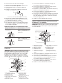
Double Ovens
The positioning of the oven feet allow a double oven to be
installed in a cutout height between 48
7
⁄8" (124.1 cm) and
52³⁄16" (132.6 cm). Refer to the following instructions to position
the feet for the size of your cabinet cutout.
Cutout height is between 48
7
⁄8" (124.1 cm)
and 50
7
⁄16" (128.1 cm)
The oven feet do not need to be installed. The oven is
configured correctly as received.
NOTE: Do not remove the spacers.
Go to the “Make Electrical Connection” section.
A. Spacers
A
B
C
A
A

9
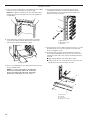
Cutout Height is between 50¹⁄2" (128.2 cm)
and 51¹⁄8" (129.9 cm)
1. Using 2 or more people, place the oven on its back on a
covered surface.
2. Install a foot on the left rear spacer using a #8-18 x ³⁄8"
screw.
NOTE: Position the foot so the long side of the foot is
facing toward the top of the oven.
A. Spacer
B. Foot
C. #8-18 x ³⁄8" screw
3. In the same manner, install a foot on the right rear of the
oven.
4. Install a front foot on the left front spacer using a #8-18 x ³⁄8"
screw.
NOTE: Position the foot so the long side of the foot is facing
toward the oven as shown.
A. Front foot
B. #8-18 x ³⁄8" screw
C. Spacer
5. In the same manner, install a front foot on the right front of
the oven.
6. Using 2 or more people, place the oven in its upright
position.
7. Go to the “Make Electrical Connection” section.
Cutout Height is between 51³⁄16" (130.0 cm)
and 52³⁄16" (132.6 cm)
1. Using 2 or more people, place the oven on its back on a
covered surface.
2. Install a foot on the left rear spacer using a #8-18 x ³⁄8"
screw.
NOTE: Position the foot so the short side of the foot is facing
toward the top of the oven.
3. In the same manner, install a foot on the right rear of the
oven.
A. Spacer
B. Foot
C. #8-18 x ³⁄8" screw
A
B
C
C
B
A
A
B
C

10
Make Electrical Connection
WARNING
Electrical Shock Hazard
Disconnect power before servicing.
Use 8 gauge solid copper wire.
Electrically ground oven.
Failure to follow these instructions can result in death,
fire, or electrical shock.
4. Install a front foot on the left front using a #8-18 x ³⁄8" screw.
NOTE: Position the foot so the long side of the foot is facing
away from the oven as shown.
5. In the same manner, install a front foot on the right front of
the oven.
A. Front foot
B. #8-18 x ³⁄8" screw
C. Spacer
6. Using 2 or more people, place the oven in its upright
position.
7. Go to the “Make Electrical Connection” section.
This oven is manufactured with a neutral (white) power supply wire and a cabinet-connected green (or bare) ground wire twisted
together.
For Double Ovens For Single Ovens
WARNING
Electrical Shock Hazard
Disconnect power before servicing.
Use 12 gauge solid copper wire.
Electrically ground oven.
Failure to follow these instructions can result in death,
fire, or electrical shock.
A
B
C

11
1. Disconnect power.
2. Feed the exible conduit from the oven through the opening
in the cabinet.
3. Remove junction box cover if it is present.
4. Install a UL-listed or CSA-approved conduit connector
to the junction box.
5. Route the exible conduit from the oven to the junction box
through a UL-isted or CSA-approved conduit connector.
6. Tighten screws on conduit connector.
7. See “Electrical Connection Options Chart” to complete
installation for your type of electrical connection.
A. UL-listed or CSA-approved conduit connector
Electrical Connection Options Chart
If your home has: Go to section:
4-wire
½"
(1.3 cm)
4-Wire Cable from Home
Power Supply
3-wire
½"
(1.3 cm)
3-Wire Cable from Home
Power Supply
4-Wire Cable from Home Power Supply
IMPORTANT: Use the 4-wire cable from home power supply
in the U.S. where local codes do not allow grounding through
neutral, New Branch circuit installations (1996 NEC), mobile
homes and recreational vehicles, new construction and in
Canada.
1. Connect the 2 black wires (B) together using a UL-listed wire
connector.
2. Connect the 2 red wires (C) together using a UL-listed wire
connector.
3. Untwist white wire from green (or bare) ground wire coming
from the oven.
4. Connect the 2 white wires (F) together using a UL-listed wire
connector.
5. Connect the green (or bare) ground wire (H) from the oven
cable to the green (or bare) ground wire (in the junction box)
using a UL-listed wire connector.
6. Install junction box cover.
A. Cable from home power supply
B. Black wires
C. Red wires
D. 4-wire exible cable from oven
E. Junction box
F. White wires
G. UL-listed wire connectors
H. Green (or bare) ground wires
I. UL-listed or CSA-approved
conduit connector
3-Wire Cable from Home Power Supply – U.S. Only
IMPORTANT: Use the 3-wire cable from home power supply
where local codes permit a 3-wire connection.
A. Cable from home power supply
B. Junction box
C. Black wires
D. White wires
E. Green (or bare) ground wire
(from oven)
F. 4-wire flexible cable from
oven
G. Red wires
H. UL-listed wire connectors
I. UL-listed or CSA-approved
conduit connector
1. Connect the 2 black wires (C) together using a UL-listed wire
connector.
2. Connect the 2 white wires (D) and the green (or bare) ground
wire (of the oven cable) using a UL-listed wire connector.
3. Connect the 2 red wires (G) together using a UL-listed wire
connector.
4. Install junction box cover.
A
B
C
D
E
F
H
G
A
I
A
D
F
H
B
C
E
G
I

12
Install Oven
2. Push against the seal area of the front frame to push the
oven into the cabinet until the back surface of the front
frame touches the front wall of the cabinet.
3. Push oven completely into the cabinet and center the oven
into the cabinet cutout.
NOTE: If you have model KEBK171B, KEBK101B,
KEBK276B, KEBK206B, KEBS179B, KEBS109B,
KEBS277B, KEBS279B, KEBS207B, KEBS209B,
KEBU109B or KEBU209B, proceed to Step 5.
1. Using 2 or more people, lift the oven partially into the cabinet
cutout. Use the oven opening as an area to grip.
NOTE: Push against seal area of the oven front frame when
pushing the oven into the cabinet. Do not push against the
outside edges.
A. Shipping foot
A. Mounting rail
B. Mounting rail hole
C. Grommet
5. Securely fasten oven to cabinet using the # 8–14 x 1" screws
provided. Insert the screws through hole in the grommet.
Do not overtighten screws.
6. On models with the foot positioned with the long side of
the foot facing toward the top of the oven, the oven vent is
taped to the side of the oven. See the following instructions
to install.
■ Align vent tab (B) with oven frame (A) as shown.
■ Using one #8-18 x ³⁄8" screw (D) on each side of the vent
tab (B), fasten the vent securely to the oven.
A. Oven frame
B. Vent tab
C. Oven vent
D. #8–18 x ³⁄8" screws
4. Insert the grommet into the mounting rail hole using
a flat-blade screwdriver. Insert the screwdriver into the
grommet and turn ¹⁄4 turn counterclockwise. Make sure
the grommet stays in position.
A
B
C
A
C
D
B

13
7. On models with the foot positioned with the short side of
the foot toward the top of the oven, the bottom vent trim
must also be installed. See the following instructions to
install.
■ Position the bottom vent trim (B) on the vent (C).
■ Install the bottom vent trim (B) to the vent (C) using two
#8–18 x ¹⁄4" screws on each side.
NOTE: On 27" (68.6 cm) models, only one #8–18 x ¹⁄4"
screw is used on each side.
A. #8–18 x ¹⁄4" screw
B. Bottom vent trim
C. Vent
8. Replace the oven racks.
9. Replace the oven door by inserting the ends of hinges into
the hinge slots in the oven frame.
10. Push the hinges in as far as they will go and open the oven
door. You should feel the oven door drop into place.
11. Rotate both hinge latches back to the locked position.
12. Check that the door is free to open and close. If it is not,
repeat the removal and installation procedures. See the
“Prepare Built-In Oven” section.
13. Repeat for lower oven door.
14. Reconnect power.
15. The display panel will light briey, and “PF” should appear
in the display.
16. If the display panel does not light, reference the “Assistance
or Service” section of the Use and Care Guide or contact
the dealer from whom you purchased your oven.
■ Align vent tab (B) with oven frame (A) as shown.
■ Using one #8-18 x ³⁄8" screw (E) on each side of the
vent tab (B), fasten the vent securely to the oven.
A. Oven frame
B. Vent tab
C. Oven vent
D. Bottom vent trim
E. #8–18 x ³⁄8" screw
A
C
D
B
E
C
B
A

14
5. Press START.
If oven(s) does not operate, check the following:
■ Household fuse is intact and tight; or circuit breaker has
not tripped.
■ Electrical supply is connected.
■ See “Troubleshooting” section in the Use and Care Guide.
6. When oven has been on for 5 minutes, feel for heat.
If you do not feel heat or if an error message appears in the
display, turn off the oven and contact a qualied technician.
7. Press UPPER CANCEL/LOWER CANCEL on double ovens,
or press CANCEL on single ovens.
If you need Assistance or Service:
Please reference the “Assistance or Service” section
of the Use and Care Guide or contact the dealer from whom
you purchased your built-in oven.
Complete Installation
1. Check that all parts are now installed. If there is an extra
part, go back through the steps to see which step was
skipped.
2. Check that you have all of your tools.
3. Dispose of/recycle all packaging materials.
4. For oven use and cleaning, read the Use and Care Guide.
Check Operation of Single and Double Ovens
1. Turn power on.
2. At rst use, set up the clock and any other preferences
if available. For more information, read the Use and Care
Guide.
3. Press BROIL on single oven models.
NOTE: Press UPPER BROIL or LOWER BROIL on double
oven models.
4. Set the temperature.

15
SÉCURITÉ DU FOUR ENCASTRÉ
Risque possible de décès ou de blessure grave si vous ne
suivez pas immédiatement les instructions.
Risque possible de décès ou de blessure grave si vous
ne suivez pas les instructions.
Tous les messages de sécurité vous diront quel est le danger potentiel et vous disent comment réduire le risque de blessure et
ce qui peut se produire en cas de non-respect des instructions.
Votre sécurité et celle des autres est très importante.
Nous donnons de nombreux messages de sécurité importants dans ce manuel et sur votre appareil ménager. Assurez-vous de
toujours lire tous les messages de sécurité et de vous y conformer.
AVERTISSEMENT
DANGER
Voici le symbole d’alerte de sécurité.
Ce symbole d’alerte de sécurité vous signale les dangers potentiels de décès et de blessures graves à vous
et à d’autres.
Tous les messages de sécurité suivront le symbole d’alerte de sécurité et le mot “DANGER” ou
“AVERTISSEMENT”. Ces mots signifient :

16
EXIGENCES D’INSTALLATION
Outillage et pièces
Rassembler les outils et composants nécessaires avant
d’entreprendre l’installation. Lire et observer les instructions
fournies avec chacun des outils de la liste ci-dessous.
Outils nécessaires
■Tournevis Phillips
■Mètre ruban
■Perceuse manuelle ou électrique (pour installation dans
un placard mural)
■Foret de 1" (2,5 cm) (pour installation dans un placard
mural)
■Niveau
■Tournevis à lame plate
Pièces nécessaires
■Connecteur de conduit (homologation UL ou CSA)
■Connecteurs de ls (homologation UL)
Pièces fournies
■Vis n° 8-14 x 1" – Four simple (2), four double (4)
■Deux vis n° 8-18 x ³⁄8" – Évent inférieur
■Quatre vis n° 8-18 x ¹⁄4" – Garniture de l’évent inférieur
■Quatre vis n° 8-18 x ³⁄8" – Pieds du four double
■Évent inférieur
■Garniture de l'évent
■Deux pieds – four double
■Deux pieds avant – four double
■Quatre oeillets – Four simple (2), four double (4)*
■Bande de mousse – four simple**
Consulter les codes locaux. Vérifier l’alimentation électrique
existante. Voir “Spécifications électriques”.
Il est recommandé de faire réaliser tous les raccordements
électriques par un électricien qualifié agréé.
* Oeillets non inclus avec les modèles KEBK171B, KEBK101B,
KEBK276B, KEBK206B, KEBS179B, KEBS109B, KEBS277B,
KEBS279B, KEBS207B, KEBS209B, KEBU109B et
KEBU209B.
** La bande de mousse n’est pas comprise avec les fours
doubles.
Exigences d’emplacement
IMPORTANT : Observer les dispositions de tous les codes
et règlements en vigueur.
■Respecter les dimensions indiquées pour les ouvertures
à découper dans les placards. Ces dimensions prennent
en compte les dégagements de séparation nécessaires.
■L’espace d’installation doit permettre la formation d’une
enceinte complète autour de la partie encastrée du four.
■Une source d’électricité avec liaison à la terre est
nécessaire. Voir la section “Spécications électriques”.
■Le boîtier de raccordement doit être situé à moins de 3"
(7,6 cm) au-dessous de la surface de support lorsque le
four est installé dans un placard mural. Un trou de diamètre
1" (2,5 cm) ou plus doit avoir été percé dans l’angle arrière
gauche ou droit de la surface de support pour le passage
du câble d’alimentation de l’appareil jusqu’au boîtier de
connexion.
REMARQUE : Pour l’installation sous un plan de travail,
on recommande que le boîtier de connexion soit situé dans
le placard adjacent, à droite ou à gauche. Dans le cas de
l’installation du boîtier de connexion sur le mur arrière,
derrière le four, le boîtier de connexion doit être encastré
et placé au centre de la partie supérieure du placard.
■La surface de support du four doit être robuste, horizontale
et en afeurement avec le bas de l’ouverture découpée
dans le placard.
■Le plancher doit pouvoir supporter le poids d’un four
simple de 129 lb (59 kg) pour les modèles de 27" (68,6 cm)
ou 154 lb (70 kg) pour les modèles de 30" (76,2 cm).
■Le plancher doit pouvoir supporter le poids d’un four
double de 251 lb (114 kg) pour les modèles de 27"
(68,6 cm) ou 288 lb (131 kg) pour les modèles de 30"
(76,2 cm).
IMPORTANT : An d’éviter d’endommager les placards,
consulter le constructeur de la maison ou le fabricant des
placards pour déterminer si les matériaux utilisés peuvent
subir un changement de couleur, une déstratication ou
d’autres dommages. Ce four a été conçu conformément
aux exigences des normes UL et CSA International et
respecte les températures maximales permises de 194°F
(90°C) pour les placards en bois.
Installation sous un plan de travail (avec table de
cuisson installée au-dessus) :
Les fours homologués pour ce type d’installation comportent
une étiquette d’homologation placée sur le dessus. Voir
les instructions d’installation du plan de travail au sujet des
dimensions de l’ouverture à réaliser et des combinaisons
approuvées four/table de cuisson (document distinct).

17
Dimensions du produit – Fours simples
Dimensions du placard – Fours simples
Four simple sous le plan de travail
(sans table de cuisson au-dessus)
Modèles de 27" (68,6 cm)
A. Hauteur hors-tout 28¾"
(72,8 cm) max.
B. Largeur d’encastrement 25
7
⁄16"
(64,6 cm) max.
C. Hauteur d’encastrement 26³⁄4"
(67,9 cm)
D. Profondeur d’encastrement
23¹⁄4" (59,1 cm) max.
E. Largeur hors-tout 27" (68,6 cm)
Modèles de 27" (68,6 cm)
A. Largeur du placard 27"
(68,6 cm) min.
B. 1¹⁄2" (3,8 cm) min. entre
le sommet de l’ouverture
découpée et la face inférieure
du plan de travail
C. 5¹⁄4" (13,3 cm) entre le bas de
l’ouverture découpée et le sol
D. Largeur de l’ouverture
découpée 25¹⁄2" (64,8 cm)
E. Hauteur de l’ouverture
découpée 28" (71,2 cm) min.
B
C
D
E
A
A
B
C
D
E
Modèles de 30" (76,2 cm)
A. Hauteur hors-tout 28¾"
(72,8 cm) max.
B. Largeur d’encastrement 28½"
(72,4 cm) max.
C. Hauteur d’encastrement 26³⁄4"
(67,9 cm)
D. Profondeur d’encastrement
23¹⁄4" (59,1 cm)
E. Largeur hors-tout 30" (76,2 cm)
Modèles de 30" (76,2 cm)
A. Largeur du placard 30"
(76,2 cm) min.
B. 1¹⁄2" (3,8 cm) min. entre
le sommet de l’ouverture
découpée et la face inférieure
du plan de travail
C. 5¹⁄4" (13,3 cm) entre le bas de
l’ouverture découpée et le sol
D. Largeur de l’ouverture
découpée 28¹⁄2" (72,4 cm)
E. Hauteur de l’ouverture
découpée 28" (71,2 cm) min.
Fours simples installés dans un placard
Modèles de 27" (68,6 cm)
A. Largeur du placard 27" (68,6 cm)
min.
B. 1" (2,5 cm) entre le sommet de
l’ouverture découpée et le bas
de la porte du placard supérieur
C. 32" (81,3 cm) entre le bas de
l’ouverture découpée et le sol
D. Largeur de l’ouverture découpée
25¹⁄2" (64,8 cm)
E. 1¹⁄2" (3,8 cm) min. entre le bas
de l’ouverture découpée et le
sommet de la porte du placard
F. Hauteur de l’ouverture découpée
recommandée 28" (71,2 cm)*
G. Profondeur de l’ouverture 24"
(60,7 cm)
F
E
B
C
A
D
G
Modèles de 30" (76,2 cm)
A. Largeur du placard 30"
(76,2 cm) min.
B. 1" (2,5 cm) entre le sommet
de l’ouverture découpée et
le bas de la porte du placard
supérieur
C. 32" (81,3 cm) entre le bas
de l’ouverture découpée
et le sol
D. Largeur de l’ouverture
découpée 28¹⁄2" (72,4 cm)
E. 1¹⁄2" (3,8 cm) min. entre le
bas de l’ouverture découpée
et le sommet de la porte du
placard
F. Hauteur de l’ouverture
découpée recommandée 28"
(71,2 cm)*
G. Profondeur de l’ouverture
24" (60,7 cm)
* REMARQUE : Pour les fours simples, la hauteur de l’ouverture
découpée peut être comprise entre 26
15
⁄16" (68,4 cm) et 29
7
⁄16"
(74,8 cm).

18
Dimensions du produit – Fours doubles
Modèles de 27" (68,6 cm)
A. Hauteur hors-tout 51³⁄16"
(130,0 cm) max.
B. Largeur d’encastrement 25
7
⁄16"
(64,6 cm) max.
C. Hauteur d’encastrement
48¹³⁄16" (124,0 cm)
D. Profondeur d’encastrement
23¹⁄4" (59,1 cm) max.
E. Largeur hors-tout 27" (68,6 cm)
Dimensions du placard – Fours doubles
Fours doubles installés dans un placard
Modèles de 27" (68,6 cm)
A. Largeur du placard 27"
(68,6 cm) min.
B. 1" (2,5 cm) entre le sommet
de l’ouverture découpée et la
porte du placard supérieur
C. 14³⁄4" (37,5 cm) entre le bas de
l’ouverture découpée et le sol
est la distance recommandée.
4"–14³⁄4" (10,2–37,5 cm) entre
le bas de l’ouverture découpée
et le sol est une distance
acceptable.
D. Largeur de l’ouverture
découpée 25¹⁄2" (64,8 cm)
E. 1¹⁄2" (3,8 cm) min. entre le bas
de l’ouverture découpée et le
sommet de la porte du placard
F. Hauteur de l’ouverture
découpée recommandée 50¹⁄4"
(127,6 cm) min.
G. Profondeur de l’ouverture 24"
(60,7 cm)
C
B
A
E
D
F
E
A
D
G
B
C
Modèles de 30" (76,2 cm)
A. Hauteur hors-tout 51³⁄16"
(130,0 cm) max.
B. Largeur d’encastrement
28½" (72,4 cm) max.
C. Hauteur d’encastrement
48¹³⁄16" (124,0 cm)
D. Profondeur d’encastrement
23¹4" (59,1 cm) max.
E. Largeur hors-tout 30" (76,2 cm)
Modèles de 30" (76,2 cm)
A. Largeur du placard 30"
(76,2 cm) min.
B. 1" (2,5 cm) entre le sommet
de l’ouverture découpée et la
porte du placard supérieur
C. 14³⁄4" (37,5 cm) entre le bas de
l’ouverture découpée et le sol
est la distance recommandée.
4"–14³⁄4" (10,2–37,5 cm) entre
le bas de l’ouverture découpée
et le sol est une distance
acceptable.
D. Largeur de l’ouverture
découpée 28¹⁄2" (72,4 cm)
E. 1¹⁄2" (3,8 cm) min. entre le bas
de l’ouverture découpée et le
sommet de la porte du placard
F. Hauteur de l’ouverture
découpée recommandée 50¹⁄4"
(127,6 cm)*
G. Profondeur de l’ouverture 24"
(60,7 cm)
* REMARQUE : Pour les fours doubles, la hauteur de l’ouverture
découpée peut être comprise entre 48
7
⁄8" (124,1 cm) et 52³⁄16"
(132,6 cm).

19
Spécifications électriques
Si on utilise un conducteur distinct de liaison à la terre lorsque
les codes le permettent, il est recommandé qu’un électricien
qualié vérie que la liaison à la terre et le calibre pour ls sont
conformes aux codes locaux.
En cas de doute quant à la qualité de la liaison à la terre
du four, consulter un électricien qualié.
Ce four doit être raccordé à un système permanent, métallique
de câblage relié à la terre.
S’assurer que la connexion électrique et le calibre des ls
sont appropriés et conformes au National Electrical Code, aux
normes ANSI/NFPA 70 – dernière édition, ou aux normes CSA
C22.1-94, au Code canadien de l’électricité, Partie 1 et C22.2
N° O-M91 – dernière édition, et à tous les codes et règlements
locaux.
Pour obtenir un exemplaire de la norme des codes ci-dessus,
contacter :
National Fire Protection Association
1 Batterymarch Park
Quincy, MA 02169-7471
CSA International
8501 East Pleasant Valley Road
Cleveland, OH 44131-5575
Raccordement électrique
Pour installer le four correctement, il faut établir le type de
raccords électriques que l’on utilisera et suivre les instructions
indiquées ici.
■Le four doit être alimenté par une source d’électricité
appropriée (caractéristiques de tension et fréquence
spéciées sur la plaque signalétique). La plaque
signalétique est située sous le tableau de commande
pour les fours simples et sous le tableau de commande
de la cavité supérieure du four pour les fours doubles.
Voir l’illustration cidessous.
Four simple
A. Plaque signalétique
■Un modèle de 7,3 à 9 kW/240 volts (5,4 à 7,4 kW/208 volts)
doit être alimenté par un circuit indépendant de 40 A. Un
modèle de 4,8 kW ou moins à 240 volts (3,6 kW ou moins
à 208 volts) doit être alimenté par un circuit indépendant
de 20 A.
■ On recommande d’utiliser un disjoncteur.
■Raccorder l’appareil directement au coupe-circuit avec
fusible ou au disjoncteur par un câble à conducteur de
cuivre et gaine métallique exible ou gaine non métallique
(avec conducteur de liaison à la terre). Voir la section
“Raccordement électrique”.
■Le câble blindé exible du four doit être connecté
directement dans le boîtier de connexion.
Four double
A. Plaque signalétique
A
A
■ Protéger par fusible les deux extrémités de la ligne.
■Ne pas couper le conduit. La longueur du conduit fournie
est destinée à faciliter l’entretien du four.
■L’installateur doit fournir un connecteur de conduit
(homologation UL ou CSA).
■Si le domicile est équipé d’un câblage en aluminium, suivre
les instructions suivantes :
1. Connecter une section de câble en cuivre massif aux
conducteurs en queue de cochon.
2. Connecter le câblage en aluminium à la section ajoutée
de câblage en cuivre en utilisant des connecteurs et/ou
des outils spécialement conçus et homologués UL pour
xer le cuivre à l’aluminium.
Appliquer la procédure recommandée par le fabricant
des connecteurs. La connexion aluminium/cuivre doit être
conforme aux codes locaux et aux pratiques de câblage
acceptées par l’industrie.
Pour connaître les spécifications de puissance pour
les modèles WOS51EC7A, WOS51EC0A, WOD51EC7A,
WOD51EC0A, WOS92EC7A, WOS92EC0A, WOD93EC7A,
WOD93EC0A, MEW7527A, MEW7530A, MEW7627A,
MEW7630A, MEW9537A, MEW9627A, MEW9530A,
MEW9630A, IBS300DS, IBS350DS, IBS550DS et IBD350DS,
se référer au tableau ci-dessous.
Tension Simple
Thermique
Simple à
convection
Double
Thermique
Double à
convection
240 VCA 3690 W 3720 W 7370 W 7400 W
208 VCA 2790 W 2820 W 5580 W 5610 W
240 VCA 15,4 A 15,5 A 30,7 A 30,8 A
208 VCA 13,4 A 13,6 A 26,8 A 27,0 A
Pour connaître les spécifications de puissance pour les
modèles KEBK171B, KEBK101B, KEBK276B, KEBK206B,
KEBS179B, KEBS109B, KEBS277B, KEBS279B, KEBS207B
et KEBS209B, se référer au tableau ci-dessous.
Tension Simple
Thermique
Simple à
convection
Double
Thermique
Double à
convection
240 VCA 4090 W 4120 W 8170 W 8200 W
208 VCA 3099 W 3122 W 6190 W 6212 W
240 VCA 17,1 A 17,2 A 34,1 A 34,2 A
208 VCA 14,9 A 15,0 A 29,8 A 29,9 A
Pour connaître les spécifications de puissance pour les
modèles KEBU109B and KEBU209B, se référer au tableau
ci-dessous.
Tension Simple à
convection
Double à
convection
240 VCA 5420 W 9500 W
208 VCA 4106 W 7197 W
240 VCA 22,6 A 39,6 A
208 VCA 19,8 A 34,6 A

20
3. Saisir les bords de la porte du four avec les deux mains et
effectuer une manoeuvre de fermeture de la porte du four,
jusqu’à la position où la fermeture de la porte n’est plus
possible. Soulever et tirer la porte du four vers soi et enlever
la porte. Conserver la/les porte(s) du four à part sur une
surface de travail couverte.
INSTRUCTIONS D’INSTALLATION
Préparation du four encastré
1. Choisir l’emplacement nal pour l’installation du four. Éviter
de percer ou d’endommager le câblage lors de l’installation.
2. Pour éviter d’endommager le plancher, placer le four sur une
feuille de carton avant l’installation. Lors des opérations de
levage, ne pas prendre prise sur la poignée ou sur une autre
partie du châssis avant.
3. Enlever les matériaux d’emballage et les rubans adhésifs
du four.
4. Enlever le sachet de matériel à l’intérieur du sachet de
documentation.
5. Enlever et conserver à part les grilles et autres composants
qu’on trouve à l’intérieur du four.
6. Si on installe un four simple sous une table de cuisson,
retirer l’endos de l’adhésif de la bande de mousse et
l’appliquer sur l’arrière du tableau de commande en
appuyant.
REMARQUE : Si l’on installe la table de cuisson dans le
placard, le bord supérieur de la bande de mousse doit se
trouver à environ 3/8" (10 mm) du bord supérieur du tableau
de commande. S’assurer que la bande de mousse se trouve
sur l’avant du placard.
7. Approcher le four et la feuille de carton de l’emplacement
nal du four.
AVERTISSEMENT
Risque du poids excessif
Utiliser deux ou plus de personnes pour déplacer et
installer le four.
Le non-respect de cette instruction peut causer
une blessure au dos ou d'autre blessure.
Dépose de la porte du four
IMPORTANT : Employer les deux mains pour enlever
la/les porte(s) du four.
1. Ouvrir la porte du four.
2. Identier les charnières de la porte du four dans les deux
angles de la porte; faire pivoter les charnières vers l’avant
jusqu’à la position de déverrouillage.
A. Porte du four – position
de verrouillage
B. Porte du four – position
de déverrouillage
A. Bande de mousse
A
B
A
La page est en cours de chargement...
La page est en cours de chargement...
La page est en cours de chargement...
La page est en cours de chargement...
La page est en cours de chargement...
La page est en cours de chargement...
La page est en cours de chargement...
La page est en cours de chargement...
-
 1
1
-
 2
2
-
 3
3
-
 4
4
-
 5
5
-
 6
6
-
 7
7
-
 8
8
-
 9
9
-
 10
10
-
 11
11
-
 12
12
-
 13
13
-
 14
14
-
 15
15
-
 16
16
-
 17
17
-
 18
18
-
 19
19
-
 20
20
-
 21
21
-
 22
22
-
 23
23
-
 24
24
-
 25
25
-
 26
26
-
 27
27
-
 28
28


Amana AWO6317SFS AWO6317SFS Installation Instruction EN
- Taper
- AWO6317SFS Installation Instruction EN
dans d''autres langues
- English: Amana AWO6317SFS
Documents connexes
Autres documents
-
Whirlpool WOD93EC7AB Guide d'installation
-
Whirlpool WOS51EC0AB Guide d'installation
-
Whirlpool WOD51EC7AB Guide d'installation
-
-
-
Whirlpool WOS51EC0AW03 Guide d'installation
-
Whirlpool WOS31ES0JS Guide d'installation
-
Whirlpool WOS31ES7JS00 Guide d'installation
-
Maytag 30" (76.2 CM) ELECTRIC SINGLE AND DOUBLE BUILT-IN OVEN Installation Instructions Manual
-
Bauknecht RBS245PRS Manuel utilisateur