Monacor accessories MMX-8 Manuel utilisateur
- Catégorie
- Amplificateur d'instruments de musique
- Taper
- Manuel utilisateur


2
Bevor Sie einschalten …
Wir wünschen Ihnen viel Spaß mit Ihrem
neuen Gerät von MONACOR. Bitte lesen
Sie diese Bedienungsanleitung vor dem
Betrieb gründlich durch und heben Sie sie
für ein späteres Nachlesen auf.
Der deutsche Text beginnt auf der Seite 4.
Avant toute installation …
Nous vous souhaitons beaucoup de
plaisir à utiliser votre nouvel appareil
MONACOR. Veuillez lire la présente no-
tice avec attention avant le fonctionne-
ment et conservez-la pour pouvoir vous y
reporter ultérieurement.
La version française se trouve page 12.
D
A
CH
F
B
CH
GB
I
Before you switch on …
We hope you will enjoy using your new
MONACOR unit. Please read these oper-
ating instructions carefully prior to opera-
tion and keep them for later reference.
The English test starts on page 8.
Prima di accendere …
Vi auguriamo buon divertimento con il vo-
stro nuovo strumento di MONACOR. Vi
preghiamo di leggere attentamente le pre-
senti istruzioni prima della messa in fun-
zione e di conservarle per un uso futuro.
Il testo italiano inizia a pagina 15.


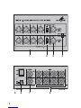
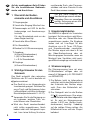
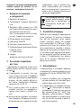
Auf der ausklappbaren Seite 3 finden
Sie alle beschriebenen Bedienele-
mente und An schlüsse.
1 Übersicht der Bedien -
elemente und Anschlüsse
1Eingangsregler
2Umschalter Eingang Mikrofon / Line
3Summenregler mit LED für die Be-
triebsanzeige und Aussteuerungs-
kontrolle
Für den Monobetrieb wird nur der
obere Regler benötigt.
4Umschalter Mono / Stereo
5Ein- /Ausschalter
6Buchse für 9-V-Stromversorgung
7Ausgänge
(6,3-mm-Klinkenbuchsen)
L (M) für Monobetrieb
L + R für Stereobetrieb
8Eingänge
(6,3-mm-Klinkenbuchsen)
2 Wichtige Hinweise für den
Gebrauch
Das Gerät entspricht allen relevanten
Richtlinien der EU und ist deshalb mit
gekennzeichnet.
GDas Gerät ist nur zur Verwendung im
Innenbereich geeignet. Schützen Sie
es vor Tropf- und Spritzwasser, hoher
Luftfeuchtigkeit und Hitze (zulässiger
Einsatztemperaturbereich 0 – 40 °C).
GVerwenden Sie für die Reinigung nur
ein trockenes, weiches Tuch, nie-
mals Wasser oder Chemikalien.
GWird das Gerät zweckentfremdet,
nicht richtig angeschlossen, falsch
be dient oder nicht fach gerecht repa-
riert, kann keine Haftung für daraus
resultierende Sach- oder Personen-
schäden und keine Garantie für das
Gerät übernommen werden.
3 Einsatzmöglichkeiten
Der MMX-8 ist speziell als Vormischer
konzipiert. Es können bis zu acht Mono-
Mikrofone oder vier Stereo-Mikrofone
angeschlossen werden. Die Eingänge
lassen sich auf Line-Pegel für den
Anschluss von z. B. Tuner, CD-Player
und Kassettenrekorder umschalten.
Der Mischer eignet sich ideal z. B. bei
der Video-Nachvertonung oder als
Mikrofongruppen-Vormischer, wenn am
Mischpult bzw. Verstärker nicht genü-
gend Mikrofoneingänge vorhanden sind.
4 Stromversorgung
Die Stromversorgung kann mit einer
9-V-Blockbatterie erfolgen oder mit
einem 9-V-Netzgerät (z. B. PSS-906DC
von MONACOR).
1) Die Batterie (nicht im Lieferumfang
enthalten) wird in das Batteriefach an
der Unterseite des Gerätes einge-
setzt. Dazu das Batteriefach auf-
schrauben.
2) Das Netzgerät wird an die Buchse
9 V (6) angeschlossen. Eine ein ge-
setzte Batterie wird dabei abgeschal-
tet. Es wird ein Kleinspannungs -
stecker 5,5 / 2,1 mm (Außen- / Innen -
durchmesser) benötigt. Unbedingt
auf die richtige Polung achten: Am
Mittelkontakt muss sich der Pluspol
befinden!
Soll das Gerät endgültig aus
dem Betrieb genommen werden,
übergeben Sie es zur umweltge-
rechten Entsorgung einem örtli-
chen Recyclingbetrieb.
D
A
CH
4

Achtung!
Wechseln Sie verbrauchte Batterien
rechtzeitig aus und entfernen Sie die
Batterie, wenn das Gerät längere Zeit
nicht benutzt wird. Sie vermeiden da-
durch ein Auslaufen der Batterie und
eine Beschädigung des Gerätes.
5 Monobetrieb
Im Monobetrieb können bis zu 8 Mono-
Signalquellen an die Eingänge (8) an-
geschlossen werden.
1) Als Ausgang dient die obere Buchse
OUTPUT L (7). An ihr wird ein Ver-
stärker oder Aufnahmegerät ange-
schlossen. Werden Mikrofone an den
Mischer angeschlossen, so muss der
Mischer an den Mikrofoneingang des
Verstärkers bzw. des Aufnahme ge -
rätes angeschlossen werden. Die un-
tere Buchse OUTPUT R ist nicht in
Betrieb.
2) Den Umschalter MONO / STEREO (4)
auf MONO stellen.
3) Mit den Umschaltern SOURCE (2)
die Art der Signalquelle wählen:
MIC = Mikrofon
LINE = Line-Eingang (Tuner, CD,
Kassette)
4) Zur Vermeidung von Einschaltgeräu-
schen beide Summenregler MASTER
LEFT und MASTER RIGHT (3) auf „0“
drehen. Das Gerät mit dem Schalter
ON / OFF (5) auf der Rückseite ein-
schalten. Die Anzeigen ON PK über
den Reglern leuchten erst kurz mit
maximaler Helligkeit auf und dann
mit geringerer Helligkeit weiter.
5) Die Eingangsregler (1) der Kanäle,
an denen kein Gerät angeschlossen
ist, auf „0“ stellen. Die anderen Reg-
ler zunächst in die Mittelstellung brin-
gen.
6) Mit dem Regler MASTER LEFT
(MONO) den Ausgangspegel einstel-
len, sodass das nachfolgende Gerät
optimal ausgesteuert ist.
7) Das Mischungsverhältnis der Ein-
gänge mit den Eingangsreglern (1)
entsprechend einstellen. Die Anzeige
ON PK über dem Regler MASTER
LEFT (MONO) dient dabei als Aus-
steuerungskontrolle. Mit dem Sum-
menregler MASTER LEFT (MONO)
die Aussteuerung eventuell korrigie-
ren.
8) Einzelne Kanäle werden bei Bedarf
mit den entsprechenden Eingangs-
reglern (1) ein- und ausgeblendet.
Das Ausgangssignal wird mit dem
Summenregler MASTER LEFT
(MONO) ein- und ausgeblendet.
6 Stereobetrieb
Im Stereobetrieb können bis zu 4 Ste-
reo-Signalquellen an die Eingänge (8)
angeschlossen werden. Dabei die lin-
ken Kanäle immer an die obere Buchse
anschließen und die rechten Kanäle an
die untere Buchse.
1) An die Buchsen (7) OUTPUT L (lin-
ker Kanal) und OUTPUT R (rechter
Kanal) einen Verstärker oder ein Auf-
nahmegerät anschließen. Werden
Mikrofone an den Mischer ange-
schlossen, so muss der Mischer an
den Mikrofoneingang des Verstär-
kers bzw. des Aufnahmegerätes an-
geschlossen werden.
Verbrauchte Batterien dürfen
nicht in den Hausmüll geworfen
werden. Geben Sie sie zur um-
weltgerechten Entsorgung nur
in den Sondermüll (z. B. Sam-
melbehälter im Einzelhandel).
5
D
A
CH

2) Den Umschalter MONO / STEREO
(4) auf STEREO stellen.
3) Mit den Umschaltern SOURCE (2)
die Art der Signalquelle wählen:
MIC = Mikrofon
LINE = Line-Eingang (Tuner, CD,
Kassette)
Beide Umschalter SOURCE müssen
auf die gleiche Position gestellt wer-
den.
4) Zur Vermeidung von Einschaltgeräu-
schen beide Summenregler MASTER
LEFT und MASTER RIGHT (3) auf „0“
drehen. Das Gerät mit dem Schalter
ON / OFF (5) auf der Rückseite ein-
schalten. Die Anzeigen ON PK über
den Reglern leuchten erst kurz mit
maximaler Helligkeit auf und dann
mit geringerer Helligkeit weiter.
5) Die Eingangsregler (1) der Kanäle,
an denen kein Gerät angeschlossen
ist, auf „0“ stellen. Die anderen Reg-
ler zunächst in die Mittelstellung brin-
gen.
6) Mit den Reglern MASTER LEFT und
MASTER RIGHT den Ausgangspe-
gel einstellen, sodass das nachfol-
gende Gerät optimal ausgesteuert
ist.
7) Das Mischungsverhältnis der Ein-
gänge mit den Eingangsreglern (1)
entsprechend einstellen. Die Anzei-
gen ON PK über den Reglern MAS-
TER LEFT und MASTER RIGHT die-
nen dabei als Aussteuerungskon-
trolle. Mit dem Summenreglern MAS-
TER LEFT und MASTER RIGHT die
Aussteuerung eventuell korrigieren.
8) Einzelne Kanäle werden bei Bedarf
mit den entsprechenden Eingangs-
reglern (1) ein- und ausgeblendet.
Das Ausgangssignal wird mit dem
Summenreglern MASTER LEFT und
MASTER RIGHT ein- und ausge-
blendet.
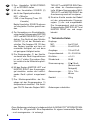
7 Technische Daten
Eingänge
MIC: . . . . . . . . . . . 5 mV/10 kΩ
LINE: . . . . . . . . . . . 50 mV/ 20 kΩ
Ausgänge: . . . . . . . . 100 mV/ 2 kΩ
Frequenzbereich: . . . 20 – 20 000 Hz
Klirrfaktor: . . . . . . . . . < 0,4 %
Störabstand: . . . . . . . 55 dB
Stromversorgung: . . . 9 V /15 mA
(Batterie oder
Netzgerät)
Abmessungen: . . . . . 150 × 115 ×
68 mm
Gewicht: . . . . . . . . . . 700 g
Änderungen vorbehalten.
D
A
CH
6
Diese Bedienungsanleitung ist urheberrechtlich für MONACOR ®INTERNATIONAL
GmbH & Co. KG geschützt. Eine Reproduktion für eigene kommerzielle Zwecke
– auch auszugsweise – ist untersagt.


GB
8
All operating elements and connec-
tions described can be found on the
fold-out page 3.
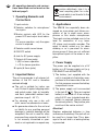
1 Operating Elements and
Connections
1Input controls
2Selector switches for microphone /
line inputs
3Master controls with LED for the
power LED and output level indica-
tion
For mono operation, only the upper
control is required.
4Selector switch mono / stereo
5ON / OFF switch
6Jack for 9 V power supply
7Outputs (6.3 mm jacks)
L (M) for mono operation
L + R for stereo operation
8Inputs (6.3 mm jacks)
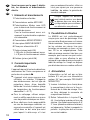
2 Important Notes
The unit corresponds to all relevant di-
rectives of the EU and is therefore
marked with .
GThe unit is suitable for indoor use
only. Protect it against dripping water
and splash water, high air humidity,
and heat (admissible ambient tem-
perature range 0 – 40 °C).
GFor cleaning only use a dry, soft
cloth, never use chemicals or water.
GNo guarantee claims for the unit and
no liability for any resulting personal
damage or material damage will be
accepted if the unit is used for other
purposes than originally intended, if it
is not correctly connected or oper-
ated, or not repaired in an expert way.
3 Applications
The MMX-8 has especially been de-
signed as a pre-mixer and allows con-
nection of up to eight mono micro-
phones or four stereo microphones.
The inputs can be switched over to line
level for connection of e. g. tuner,
CD player and cassette recorder. The
mixer is ideally suited e. g. for video
dubbing or as a pre-mixer for micro-
phone groups if there are not sufficient
microphone inputs at the mixer or am-
plifier.
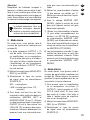
4 Power Supply
The power can be supplied via a 9 V
battery or a 9 V power supply unit (e. g.
PSS-906DC from MONACOR).
1) The battery (not supplied with the
unit) is inserted into the battery com-
partment at the lower side of the unit.
For this purpose unscrew the battery
compartment cover.
2) The power supply unit is connected
to the jack 9 V (6). Then an inserted
battery is switched off. A low voltage
plug 5.5 / 2.1 mm (outside / inside dia -
meter) is required. Always observe
the correct polarity: The positive pole
must be at the centre contact!
Attention!
Replace exhausted batteries in time
and remove the battery if the unit will not
be used for a longer time. Thus, dam-
age to the unit due to a leaking battery
is prevented.
If the unit is to be put out of op-
eration definitively, take it to a
local recycling plant for a dis-
posal which is not harmful to the
environment.

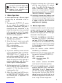
5 Mono Operation
In mono operation up to 8 mono signal
sources may be connected to the in-
puts (8).
1) The upper jack OUTPUT L (7) serves
as an output. An amplifier or a
recorder is connected to this jack. If
microphones are connected to the
mixer, the mixer has to be connected
to the microphone input of the ampli-
fier or recorder. The lower jack OUT-
PUT R is out of operation.
2) Set the selector switch MONO /
STEREO (4) to MONO.
3) Select the type of signal source with
the selector switches SOURCE (2):
MIC = microphone
LINE = line input (tuner, CD,
cassette)
4) To prevent switching noise, set both
controls MASTER LEFT and MAS-
TER RIGHT (3) to “0”. Switch on the
unit with the switch ON / OFF (5) on
the rear side. First the LEDs ON PK
above the controls shortly light up at
maximum brightness and then con-
tinue to light at lower brightness.
5) Set the input controls (1) of the chan-
nels to which no unit has been con-
nected to “0”. Set the other controls
to mid-position first.
6) Adjust the output level with the con-
trol MASTER LEFT (MONO) so that
the following unit is adjusted to an
optimum level.
7) Adjust the mixing ratio of the inputs
with the input controls (1) accord-
ingly. The LED ON PK above the
control MASTER LEFT (MONO)
serves as a level indicator. Correct
the output level with the control MAS-
TER LEFT (MONO), if required.
8) Individual channels are faded in and
out with the corresponding input con-
trols (1), if required. The output signal
is faded in and out with the control
MASTER LEFT (MONO).
6 Stereo Operation
In stereo operation up to 4 stereo signal
sources may be connected to the inputs
(8). The left channels are always con-
nected to the upper jack and the right
channels to the lower jack.
1) Connect an amplifier or a recorder to
the jacks (7) OUTPUT L (left chan-
nel) and OUTPUT R (right channel).
If microphones are connected to the
mixer, the mixer must be connected
to the microphone input of the ampli-
fier or recorder.
2) Set the selector switch MONO /
STEREO (4) to STEREO.
3) Select the type of signal source with
the selector switches SOURCE (2):
MIC = microphone
LINE = line input (tuner, CD,
cassette)
Both selector switches SOURCE
must be set to the same position.
4) To prevent switching noise, set both
controls MASTER LEFT and MAS-
TER RIGHT (3) to “0”. Switch on the
unit with the switch ON / OFF (5) on
the rear side. First the LEDs ON PK
above the controls shortly light up at
maximum brightness and then con-
tinue to light at lower brightness.
Do not put exhausted batteries
into the household rubbish but
take them to a special waste
disposal (e. g. collective con-
tainer at your retailer).
9
GB

5) Set the input controls (1) of the chan-
nels to which no unit has been con-
nected to “0”. Set the other controls
to mid-position first.
6) Adjust the output level with the con-
trols MASTER LEFT and MASTER
RIGHT so that the following unit is
adjusted to an optimum level.
7) Adjust the mixing ratio of the inputs
with the input controls (1) accord-
ingly. The LEDs ON PK above the
controls MASTER LEFT and MAS-
TER RIGHT indicate the output level.
Correct the output level with the con-
trols MASTER LEFT and MASTER
RIGHT, if required.
8) Individual channels are faded in and
out with the corresponding input con-
trols (1), if required. The output signal
is faded in and out with the controls
MASTER LEFT and MASTER RIGHT.
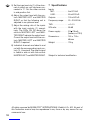
7 Specifications
Inputs
MIC: . . . . . . . . . . . 5 mV/10 kΩ
LINE: . . . . . . . . . . . 50 mV/ 20 kΩ
Outputs: . . . . . . . . . . 100 mV/ 2 kΩ
Frequency range: . . . 20 – 20 000 Hz
THD: . . . . . . . . . . . . . < 0.4 %
S / N ratio: . . . . . . . . . 55 dB
Power supply: . . . . . . 9 V /15 mA
(battery or PSU)
Dimensions: . . . . . . . 150 × 115 ×
68 mm
Weight: . . . . . . . . . . . 700 g
Subject to technical modification.
GB
10
All rights reserved by MONACOR ®INTERNATIONAL GmbH & Co. KG. No part of
this instruction manual may be reproduced in any form or by any means for any
commercial use.


Vous trouverez sur la page 3, déplia-
ble, les éléments et branchements
décrits.
1 Eléments et branchements
1Potentiomètres dʼentrée
2Commutateurs entrée MIC / LINE
3Potentiomètres Master avec LED
pour le témoin de fonctionnement et
contrôle de niveau
Pour le fonctionnement mono, uni-
quement le potentiomètre supérieur
est nécessaire.
4Commutateur MONO / STEREO
5Interrupteur MARCHE /ARRET
6Prise pour alimentation 9 V
7Sorties (prises jack 6,35)
L (M) pour le fonctionnement mono
L + R pour le fonctionnement stéréo
8Entrées (prises jack 6,36)
2 Conseils importants
dʼutilisation
Lʼappareil répond à toutes les directives
nécessaires de lʼUnion européenne et
porte donc le symbole .
GLʼappareil nʼest conçu que pour une
utilisation en intérieur. Protégez-le
des éclaboussures, de tout type de
projections dʼeau, dʼune humidité
élevée de lʼair et de la chaleur (plage
de température de fonctionnement
admissible 0 – 40 °C).
GPour le nettoyage, utilisez unique-
ment un chiffon sec et doux, en aucun
cas, de produits chimiques ou dʼeau.
GNous déclinons toute responsabilité
en cas de dommages matériels ou
corporels consécutifs si lʼappareil est
utilisé dans un but autre que celui
pour lequel il a été conçu, sʼil nʼest
pas correctement branché, utilisé ou
nʼest pas réparé par une personne
habilitée ; de même, la garantie de-
viendrait caduque.
3 Possibilités dʼutilisation
La MMX-8 est tout particulièrement
conçue pour servir de prémixage. Vous
pouvez relier 8 micros mono ou 4 micros
stéréo maximum. Vous pouvez commu-
ter les entrées sur niveau Line pour
brancher par exemple un tuner, un lec-
teur CD ou un magnétophone. Cette
table de mixage convient très bien, par
exemple, pour assurer une post-sonori-
sation vidéo ou pour effectuer le pré-
mixage dʼun groupe de micros lorsque la
table de mixage ou lʼampli ne dispose
pas dʼentrées micro en nombre suffisant.
4 Alimentation
Lʼalimentation se fait soit par un bloc
batterie 9 V soit par une alimentation
secteur 9 V (par exemple PSS-906DC
MONACOR).
1) Insérez la batterie (non livrée) dans
le compartiment situé sur la face in-
férieure de la table de mixage. Pour
ce faire, dévissez le couvercle du
compartiment batterie.
2) Reliez lʼalimentation à la prise 9 V
(6). Une batterie insérée est hors de
service. Une fiche basse tension 5,5 /
2,1 mm (diamètre extérieur / intérieur)
est nécessaire. Veillez à respecter la
polarité : le pôle plus doit se trouver
au contact médian.
Lorsque l’appareil est définitive-
ment retiré du service, vous devez
le déposer dans une usine de re-
cyclage adaptée pour contribuer à
son élimination non polluante.
F
B
CH
12

Attention !
Remplacez les batteries usagées à
temps et nʼoubliez pas de retirer la bat-
terie si vous ne devez pas utiliser votre
table de mixage pendant une longue pé-
riode. Vous éviterez ainsi que la batterie
ne coule et nʼendommage votre appareil.
5 Mode mono
En mode mono, vous pouvez relier 8
sources de signal mono maximum aux
entrées (8).
1) La prise supérieure OUTPUT L (7)
sert de sortie. Vous pouvez y relier
un amplificateur ou un enregistreur.
Si vous reliez des micros à la table, il
faut relier la table à lʼentrée micro de
lʼamplificateur ou de lʼenregistreur.
La prise inférieure OUTPUT R est
hors de service.
2) Mettez le commutateur MONO / STE-
REO (4) sur MONO.
3) Sélectionnez le type de source
de signal avec les commutateurs
SOURCE (2) :
MIC = microphone
LINE = entrée ligne (tuner, CD,
cassette)
4) Pour éviter tout bruit lors de lʼallu-
mage de la table, mettez les deux po-
tentiomètres MASTER LEFT et
MASTER RIGHT (3) sur “0”. Allumez
la table de mixage avec lʼinterrupteur
ON / OFF (5) sur la face arrière. Les
LEDs ON PK au-dessus des poten-
tiomètres sʼallument brièvement uni-
quement avec une luminosité maxi-
male puis avec une luminosité plus
faible.
5) Mettez les potentiomètres dʼentrée
(1) des canaux non utilisés sur “0”.
Mettez les autres dʼabord sur la posi-
tion médiane.
6) Avec le réglage MASTER LEFT
(MONO), réglez le niveau de sortie
pour que lʼappareil suivant soit géré
de manière optimale.
7) Utilisez les potentiomètres dʼentrée
(1) pour mixer convenablement les
entrées. La LED ON PK au-dessus
du potentiomètre MASTER LEFT
(MONO) sert dʼindicateur de niveau.
Vous avez la possibilité de corriger le
niveau de sortie avec le potentiomè-
tre MASTER LEFT (MONO).
8) Les potentiomètres dʼentrée (1) per-
mettent de faire entrer et sortir des
canaux individuels, si besoin. Faites
entrer et sortir le signal de sortie avec
le potentiomètre MASTER LEFT
(MONO).
6 Mode stéréo
En mode stéréo, vous pouvez relier 4
sources de signal stéréo maximum aux
entrées (8). Reliez toujours les canaux
gauches à la prise supérieure et les ca-
naux droits à la prise inferieure.
1) Vous pouvez relier un amplificateur
ou un enregistreur aux prises (7)
OUTPUT L (canal gauche) et OUT-
PUT R (canal droit). Si vous reliez
des micros à la table, il faut relier la
table à lʼentrée micro de amplifica-
teur ou de lʼenregistreur.
2) Mettez le commutateur MONO / STE-
REO (4) sur STEREO.
3) Sélectionnez le type de source
de signal avec les commutateurs
SOURCE (2) :
Ne jetez les batteries usagées dans
la poubelle domestique. Pour une
élimination écologique, déposez-
les dans un container spécifique ou
ramenez-les chez votre détaillant.
13
F
B
CH

MIC = microphone
LINE = entrée ligne (tuner, CD,
cassette)
Les deux commutateurs SOURCE
doivent être sur la même position.
4) Pour éviter tout bruit lors de lʼallu-
mage de la table, mettez les deux
potentiomètres MASTER LEFT et
MASTER RIGHT (3) sur “0”. Allumez
la table de mixage avec lʼinterrupteur
ON / OFF (5) sur la face arrière. Les
LEDs ON PK au-dessus des poten-
tiomètres sʼallument brièvement uni-
quement avec une luminosité maxi-
male puis avec une luminosité plus
faible.
5) Mettez les potentiomètres dʼentrée
(1) des canaux non utilisés sur “0”.
Mettez les autres dʼabord sur la posi-
tion médiane.
6) Avec les potentiomètres MASTER
LEFT et MASTER RIGHT, réglez le
niveau de sortie pour que lʼappareil
suivant soit géré de manière optimale.
7) Utilisez les potentiomètres dʼentrée
(1) pour mixer convenablement les
entrées. Les LEDs ON PK au-dessus
des potentiomètres MASTER LEFT
et MASTER RIGHT servent de
contrôle de niveau. Vous avez la
possibilité de corriger le niveau de
sortie avec les potentiomètres MAS-
TER LEFT et MASTER RIGHT.
8) Les potentiomètres dʼentrée (1) per-
mettent de faire entrer et sortir des
canaux individuels, si besoin. Faites
entrer et sortir le signal de sortie avec
les potentiomètres MASTER LEFT et
MASTER RIGHT.
7 Caractéristiques techniques
Entrées
MIC : . . . . . . . . . . . 5 mV/10 kΩ
LINE : . . . . . . . . . . 50 mV/ 20 kΩ
Sorties : . . . . . . . . . . 100 mV/ 2 kΩ
Bande passante : . . . 20 – 20 000 Hz
Taux de distorsion : . < 0,4 %
Rapport signal
sur bruit : . . . . . . . . . 55 dB
Alimentation : . . . . . . 9 V /15 mA
(batterie ou bloc
secteur)
Dimensions : . . . . . . . 150 × 115 ×
68 mm
Poids : . . . . . . . . . . . 700 g
Tout droit de modification réservé.
F
B
CH
14
Notice dʼutilisation protégée par le copyright de MONACOR ®INTERNATIONAL
GmbH & Co. KG. Toute reproduction même partielle à des fins commerciales est
interdite.

A pagina 3, se aperta completamente,
vedrete sempre gli elementi di co-
mando e i collegamenti descritti.
1 Elementi di comando
e collegamenti
1Regolatori di ingresso
2Commutatore ingresso Microfono /
Line
3Regolatori delle somme con LED
per la spia di funzionamento e per il
controllo del livello d'uscita
Per il funzionamento mono è richie-
sto solo il regolatore superiore.
4Commutatore mono / stereo
5Interruttore ON / OFF
6Presa per alimentazione 9 V
7Uscite (prese per jack mono 6,3 mm)
L (M) per mono
L + R per stereo
8Ingressi
(prese per jack mono 6,3 mm)
2 Avvertenze importante
per lʼuso
Lʼapparecchio è conforme a tutte le di-
rettive rilevanti dellʼUE e pertanto porta
la sigla .
GLʼapparecchio è previsto solo per
lʼuso allʼinterno di locali. Proteggerlo
dallʼacqua gocciolante e dagli spruzzi
dʼacqua, da alta umidità dellʼaria e
dal calore (temperatura dʼimpiego
ammessa fra 0 e 40 °C).
GPer la pulizia usare solo un panno
morbido, asciutto; non impiegare in
nessun caso acqua o prodotti chi-
mici.
GNel caso dʼuso improprio, di collega-
menti sbagliati, dʼimpiego scorretto o
di riparazione non a regola dʼarte del-
lʼapparecchio, non si assume nes-
suna responsabilità per eventuali
danni consequenziali a persone o a
cose e non si assume nessuna ga-
ranzia per lʼapparecchio.
3 Possibilità dʼimpiego
MMX-8 è stato concepito specialmente
come premixer. Si possono collegare
fino ad otto microfoni mono oppure
quattro microfoni stereo. Gli ingressi
sono commutabili su LINE per il colle-
gamento di un tuner, di un lettore CD e
di un registratore a cassette. Il mixer è
ideale p. es. per creare una pista sonora
su un nastro video oppure come premi-
xer per gruppi di microfoni nei casi in cui
il mixer o lʼamplificatore non dispon-
gono di un numero sufficiente di in-
gressi per microfono.
4 Alimentazione
Lʼalimentazione è possibile mediante
una batteria 9 V oppure mediante un ali-
mentatore 9 V (p. es. MONACOR PSS-
906DC).
1) Inserire la batteria (non compresa)
nel vano batteria sul fondo dellʼappa-
recchio dopo aver tolto la vite.
2) Lʼalimentatore, se collegato alla pre -
sa 9 V (6), disinserisce la batteria
se presente. È richiesto uno spinotto
per alimentazione DC 5,5 / 2,1 mm
(diametro esterno / interno). Rispet-
tare assolutamente la corretta pola-
rità: sul contatto centrale si deve tro-
vare il polo positivo!
Se si desidera eliminare lʼappa-
recchio definitivamente, conse-
gnarlo per lo smaltimento ad
unʼistituzione locale per il rici-
claggio.
15
I

Attenzione!
Sostituire tempestivamente la batteria
consumata, e toglierla se lʼapparecchio
resta inattivo per parecchio tempo. Si
evita così la fuoriuscita di acidi dalla bat-
teria, che potrebbe danneggiare lʼappa-
recchio.
5 Funzionamento mono
Con funzionamento mono, agli ingressi
(8) si possono collegare fino a 8 sor-
genti mono.
1) La presa superiore OUTPUT L (7)
serve da uscita per il collegamento di
un amplificatore o di un registratore.
Nel caso di collegamento di microfoni,
il mixer stesso deve essere collegato
con lʼingresso microfono dellʼamplifi-
catore o del registratore. La presa in-
feriore OUTPUT R è disattivata.
2) Posizionare il commutatore MONO /
STEREO (4) su MONO.
3) Selezionare il tipo di sorgente con il
commutatore SOURCE (2):
MIC = microfono
LINE = ingresso Line (tuner, CD, re-
gistratore a cassette)
4) Per evitare i rumori di commuta-
zione, girare i due regolatori delle
somme MASTER LEFT e MASTER
RIGHT (3) sullo “0”. Accendere lʼap-
parecchio con lʼinterruttore ON / OFF
(5) sul retro. Le spie ON PK sopra i
regolatori si accendono dapprima
brevemente con luminosità massima
e rimangono quindi accese con lumi-
nosità minore.
5) Posizionare sullo “0” i regolatori di in-
gresso (1) dei canali non collegati
con nessuna sorgente. Dapprima
portare gli altri regolatori in posizione
centrale.
6) Con il regolatore MASTER LEFT
(MONO) impostare il livello dʼuscita,
cosicché che lʼapparecchio a valle
sia regolato in modo ottimale.
7) Miscelare gli ingressi con i regolatori
di ingresso (1). La spia ON PK sopra
il regolatore MASTER LEFT (MONO)
serve in questo caso come con-
trollo del livello d'uscita. Correggere
eventualmente con MASTER LEFT
(MONO).
8) Per singoli canali, le dissolvenze
sono possibili mediante i regolatori di
ingresso (1). Per le dissolvenze del
segnale di uscita ci si serve del rego-
latore delle somme MASTER LEFT
(MONO).
6 Funzionamento stereo
Con funzionamento stereo si possono
collegare agli ingressi (8) fino a 4 sor-
genti stereo. Collegare i canali di sini-
stra sempre con le prese superiori e
quelli di destra con le prese inferiori.
1) Collegare un amplificatore o un regi-
stratore alle prese (7) OUTPUT L
(canale di sinistra) e OUTPUT R (ca-
nale di destra). Nel caso di collega-
mento di microfoni, il mixer stesso
deve essere collegato con lʼingresso
microfono dellʼamplificatore o del re-
gistratore.
2) Posizionare il commutatore MONO /
STEREO (4) su STEREO.
3) Selezionare il tipo di sorgente con il
commutatore SOURCE (2):
Non gettare le batterie scariche
nelle immondizie di casa bensì
negli appositi contenitori (p. es.
presso il vostro rivenditore).
I
16

MIC = microfono
LINE = ingresso Line (tuner, CD, re-
gistratore a cassette)
Entrambi i commutatori SOURCE
devono essere regolati sulla stessa
posizione.
4) Per evitare i rumori di commuta-
zione, girare i due regolatori delle
somme MASTER LEFT e MASTER
RIGHT (3) sullo “0”. Accendere lʼap-
parecchio con lʼinterruttore ON / OFF
(5) sul retro. Le spie ON PK sopra i
regolatori si accendono dapprima
brevemente con luminosità massima
e rimangono quindi accese con lumi-
nosità minore.
5) Posizionare sullo “0” i regolatori di
ingresso (1) dei canali non collegati
con nessuna sorgente. Dapprima
portare gli altri regolatori in posizione
centrale.
6) Con i regolatori MASTER LEFT e
MASTER RIGHT impostare il livello
dʼuscita, cosicché che lʼapparecchio
a valle sia regolato in modo ottimale.
7) Miscelare gli ingressi con i regola-
tori di ingresso (1). Le spie ON PK
sopra i regolatori MASTER LEFT e
MASTER RIGHT servono in questo
caso come controllo del livello
d'uscita. Correggere eventualmente
con MASTER LEFT e MASTER
RIGHT.
8) Per singoli canali, le dissolvenze
sono possibili mediante i regolatori di
ingresso (1). Per le dissolvenze dl
segnale di uscita ci si serve dei rego-
latori delle somme MASTER LEFT e
MASTER RIGHT.
7 Dati tecnici
Ingressi
MIC: . . . . . . . . . . . 5 mV/10 kΩ
LINE: . . . . . . . . . . . 50 mV/ 20 kΩ
Uscite: . . . . . . . . . . . 100 mV/ 2 kΩ
Banda passante: . . . 20 – 20 000 Hz
Fattore di distorsione: < 0,4 %
Rapporto S / R: . . . . . 55 dB
Alimentazione: . . . . . 9 V /15 mA
(batteria opp.
alimentatore)
Dimensioni: . . . . . . . . 150 × 115 ×
68 mm
Peso: . . . . . . . . . . . . 700 g
Con riserva di modifiche tecniche.
17
I
La MONACOR ®INTERNATIONAL GmbH & Co. KG si riserva ogni diritto di elabo-
razione in qualsiasi forma delle presenti istruzioni per lʼuso. La riproduzione – anche
parziale – per propri scopi commerciali è vietata.

-
 1
1
-
 2
2
-
 3
3
-
 4
4
-
 5
5
-
 6
6
-
 7
7
-
 8
8
-
 9
9
-
 10
10
-
 11
11
-
 12
12
-
 13
13
-
 14
14
-
 15
15
-
 16
16
-
 17
17
-
 18
18


Monacor accessories MMX-8 Manuel utilisateur
- Catégorie
- Amplificateur d'instruments de musique
- Taper
- Manuel utilisateur
dans d''autres langues
- italiano: Monacor accessories MMX-8 Manuale utente
- English: Monacor accessories MMX-8 User manual
- Deutsch: Monacor accessories MMX-8 Benutzerhandbuch