
IMPORTANT: Keep these user instructions for reference.
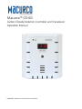
Macurco™ CD-6G
Carbon Dioxide Detector, Controller and Transducer
Operation Manual

Macurco CD-6G Operation Manual
REV – 1.0.1 [34-2900-0510-9 ] 2 | Page
Table of Contents
1 General Safety Information ........................................................................................................................................................ 5
1.1 List of warnings ................................................................................................................................................................. 5
2 Use Instructions and Limitations ................................................................................................................................................ 6
2.1 Use For .............................................................................................................................................................................. 6
2.2 Do NOT use for .................................................................................................................................................................. 6
2.3 Features ............................................................................................................................................................................. 7
2.4 Specifications .................................................................................................................................................................... 7
2.4.1 6-Series Low Voltage ..................................................................................................................................................... 7
3 Installation Instructions ............................................................................................................................................................. 8
3.1 Location ............................................................................................................................................................................. 8
3.2 Installation ......................................................................................................................................................................... 9
3.2.1 6-Series Low Voltage ..................................................................................................................................................... 9
3.3 Wiring Connections ......................................................................................................................................................... 14
3.3.1 6-Series Low Voltage ................................................................................................................................................... 14
4 Operations ............................................................................................................................................................................... 16
4.1 Power up ......................................................................................................................................................................... 16
4.2 Display turned “On” ........................................................................................................................................................ 16
4.3 Display turned “Off” ........................................................................................................................................................ 16
4.4 4-20mA Loop ................................................................................................................................................................... 17
4.5 Default – Factory Settings ............................................................................................................................................... 17
4.5.1 Selecting Default Configuration – “dEF” ..................................................................................................................... 18
4.5.2 Power-Up Test Setting – “PUt” ................................................................................................................................... 18
4.5.3 Display Setting – “dSP” ............................................................................................................................................... 18
4.5.4 Buzzer Setting – “bUZ” ................................................................................................................................................ 18
4.5.5 Alarm Relay Setting – “ArS” ........................................................................................................................................ 19
4.5.6 Alarm Relay Configuration – “Arc” .............................................................................................................................. 19
4.5.7 Fan Relay Setting – “FrS”............................................................................................................................................. 19
4.5.8 Fan Relay Delay Setting – “Frd” .................................................................................................................................. 19
4.5.9 Fan Relay Minimum Runtime Setting – “Frr” .............................................................................................................. 19
4.5.10 Fan Relay Latching Setting – “FrL” .......................................................................................................................... 19
4.5.11 Trouble Fan Setting – “tFS” .................................................................................................................................... 19
4.5.12 Awareness Alarm – “AAS” ...................................................................................................................................... 20
4.5.13 4-20mA Output setting – “420” .............................................................................................................................. 20
4.5.14 Calibration Period Settings – “CAL” ........................................................................................................................ 20

Macurco CD-6G Operation Manual
REV – 1.0.1 [34-2900-0510-9 ] 3 | Page
5 Troubleshooting ....................................................................................................................................................................... 21
5.1 On-Board Diagnostics ...................................................................................................................................................... 21
5.1.1 4-20mA troubleshooting. ............................................................................................................................................ 21
5.1.2 “t” Error Codes ............................................................................................................................................................ 21
5.2 Sensor Poisons ................................................................................................................................................................ 22
5.3 End-of-Life Signal ............................................................................................................................................................. 22
6 Maintenance ............................................................................................................................................................................ 22
6.1 Sensor Life Reset ............................................................................................................................................................. 23
6.2 Cleaning ........................................................................................................................................................................... 23
6.3 Testing ............................................................................................................................................................................. 23
6.3.1 Operation Test ............................................................................................................................................................ 24
6.3.2 Manual Operation Test ............................................................................................................................................... 24
6.4 Calibration and Test Kits .................................................................................................................................................. 25
6.4.1 Field Calibration Kit ..................................................................................................................................................... 25
6.5 Gas Testing ...................................................................................................................................................................... 25
6.5.1 Testing the Fan Relay .................................................................................................................................................. 25
6.5.2 Testing the Alarm Relay .............................................................................................................................................. 26
6.5.3 Testing the 4-20mA loop ............................................................................................................................................. 27
6.5.4 Aerosol Test ................................................................................................................................................................ 27
6.6 Field Calibration Procedure ............................................................................................................................................. 28
6.6.1 CD-6G .......................................................................................................................................................................... 28
7 Appendix A – Table of Figures .................................................................................................................................................. 29
8 Appendix B – Menu Structure .................................................................................................................................................. 30
8.1 Main Menu ...................................................................................................................................................................... 30
8.2 Auto Test Menu “bUZ” .................................................................................................................................................... 31
8.3 Configuration Menu “CON” ............................................................................................................................................. 32
8.4 Test Menu “tst” ............................................................................................................................................................... 38
8.5 CAL Menu ........................................................................................................................................................................ 39
8.6 SEN Menu ........................................................................................................................................................................ 40
9 Macurco Gas Detection Product limited warranty .................................................................................................................. 41
Technical Support Contact Information ........................................................................................................................................ 41
General Contact Information ........................................................................................................................................................ 41

Macurco CD-6G Operation Manual
REV – 1.0.1 [34-2900-0510-9 ] 5 | Page
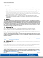
1 General Safety Information
The following instructions are intended to serve as a general guideline for the use of the Macurco CD-6G Carbon Dioxide
Detector. This manual is not to be considered all-inclusive, nor is it intended to replace the policy and procedures for your
facility. If you have any doubts about the applicability of the equipment to your situation, consult an industrial hygienist or call
Technical Support at 1-844-325-3050.
1.1 List of warnings
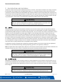
WARNING
Each person using this equipment must read and understand the information in this user manual before
use. Use of this equipment by untrained or unqualified persons or use that is not in accordance with this
user manual, may adversely affect product performance.
Use only for monitoring the gas which the sensor and monitor is designed to detect. Failure to do so may
result in exposures to gases not detectable and cause serious injury or death. For proper use, see
supervisor or user manual, or contact Technical Support at 1-844-325-3050.
This equipment may not function effectively below 32°F or above 122°F (0°C or above 50°C). Using the
detector outside of this temperature range may adversely affect product performance.
This detector helps monitor for the presence and concentration level of a certain specified airborne gas.
Misuse may produce an inaccurate reading, which means that higher levels of the gas being monitored
may be present and could result in overexposure and cause serious injury or death. For proper use, see
supervisor or User manual, or contact Technical Support at 1-844-325-3050.
Only qualified technicians should open the detector case and service the internal circuits. Ensure power
is de-energized from the detector relays prior to servicing the unit. Failure to do so may result in electrical
shock.
Do not disassemble unit or attempt to repair or modify any component of this instrument. This
instrument contains no user serviceable parts, and substitution of components may impair product
performance.
Using a certified gas with a concentration other than the one listed for this detector when conducting a
calibration or calibration verification test (bump test) will produce inaccurate readings. This means that
higher levels of the gas being monitored may be present and could result in overexposure. For proper
use, see supervisor or User manual, or contact Technical Support at 1-844-325-3050.
The following steps must be performed when conducting a calibration or calibration verification test
(bump test) to ensure proper performance of the monitor. Failure to do so may adversely affect product
performance.
• When performing a calibration or calibration verification test (bump test), only use certified
calibration gas at the required concentration level.
• Do not test with expired calibration gas.
• Do not cover or obstruct display or visual alarm cover.
• Ensure sensor inlets are unobstructed and are free of debris
Failure to follow instructions outlined in this user manual can result in sickness or death.

Macurco CD-6G Operation Manual
REV – 1.0.1 [34-2900-0510-9 ] 6 | Page
2 Use Instructions and Limitations
The Macurco CD-6G a dual relay Carbon Dioxide (COP2P) detector, controller, and transducer available in low voltage. The CD-6G
has selectable 4-20 mA output, buzzer and digital display options. It is an electronic detection system used to measure the
concentration of Carbon Dioxide and provide feedback and automatic ventilation control to help reduce COP2P concentrations in
CO2 enrichment areas such agriculture production: cannabis grow rooms, green houses, CO2 storage rooms, CO2 processes, etc.
. The CD-6G is a low-level meter capable of displaying from 0 to 5.0% vol. of Carbon Dioxide with a display resolution of 0.01%
vol. (measurement is % by volume). The CD-6G is factory calibrated and 100% tested for proper operation.
WARNING
Each person using this equipment must read and understand the information in this user manual
before use. Use of this equipment by untrained or unqualified persons or use that is not in
accordance with this user manual, may adversely affect product performance.
2.1 Use For
The CD-6G provides COP2P detection and automatic ventilation control for CO2 enrichment areas such agriculture production:
cannabis grow rooms, green houses, CO2 storage rooms, CO2 processes, etc. Carbon dioxide is a colorless, odorless gas that is
produced both by people exhaling COP2P as well the burning of gasoline, coal, oil, and wood. The outdoor concentration of carbon
dioxide can vary from 350-450 parts per million (ppm) or higher in areas with high vehicle traffic or industrial activity. The
indoor COP2P level depends upon the number of people present, how long an area has been occupied, the amount of outdoor
fresh air entering the area, enrichment processes, and other factors. COP2P concentrations indoors can vary several hundred parts
per million in areas with many people present for an extended period and where fresh air ventilation is limited. Outdoor "fresh"
air ventilation is important as it can dilute COP2P levels of the indoor environment. The amount of fresh air that should be supplied
to a room depends on the type of facility and room. Ventilation should keep carbon dioxide concentrations below 1000 ppm
and create indoor air quality conditions that are acceptable to most individuals.
For applications storing or using COP2P tanks, the detector will provide notification in the event of a gas leak. Such applications
include but are not limited to food storage, beverage dispensing, agriculture, fire suppression, medical, etc.
42TNote:42T This applies when used in typical indoor ambient air. The CD-6G can be used stand alone, with the Macurco Detection and
Ventilation Control Panel, other 12 VAC or 24 VDC fire/security panels or building automation systems.
WARNING
Use only for monitoring the gas which the sensor and monitor is designed to detect. Failure to do
so may result in exposures to gases not detectable and cause serious injury or death. For proper
use, see supervisor or user manual, or contact Technical Support at 1-844-325-3050.
2.2 Do NOT use for
The CD-6G is not intended for use in hazardous locations or industrial applications such as refineries, chemical plants, etc. Do
not mount the CD-6G where the normal ambient temperature is below 32°F or exceeds 122°F (0°C or above 50°C). The CD-6G
mounts on a type 4S electrical box supplied by the contractor. Do not install the CD-6G inside another box unless it has good air
flow through it.
WARNING
This equipment may not function effectively below 32°F or above 122°F (0°C or above 50°C). Using
the detector outside of this temperature range may adversely affect product performance.

Macurco CD-6G Operation Manual
REV – 1.0.1 [34-2900-0510-9 ] 7 | Page
2.3 Features
• ETL LISTED to UL 61010-1, Certified to CSA C22.2#61010-1
• Low level meter capable of displaying from 0-5.0% vol. of COP 2
• Sensor Resolution of 0.01% vol.
• Selectable fan and alarm relay activation
• 5 A SPDT fan relay for control of ventilation systems / communication with Alarm system
• 0.5 A N.O. or N.C. alarm relay connects to warning devices or control panels.
• 4-20 mA Current Loop
• Mounts on a standard 4x4 electrical box and becomes cover for the box.
• Supervised system: any internal detector problem will cause the fan & alarm relay to activate.
• Carbon Dioxide sensor has an expected 15-year life. EOL indicator after 180 months of sensor power-up
• Calibration verification test kit is available. One screw allows access for gas test.
2.4 Specifications
• Shipping Weight: 1 pound (0.45 kg)
• Size: 4 1/2 x 4 x 2 1/8 in. (11.4 X 11.4 X 5.3 cm)
• Color: White or Dark Gray
• Connections: plugs/terminals
• Mounting box: (not included) 4x4 electric.
• Fan relay: 5 A, 240 VAC, pilot duty, SPDT, latching or non-latching
• Fan relay actuation: selectable at “dIS” (disabled), 0.09, 0.1, 0.11, 0.12, …0.2(default), ….3.50, 4.0.
• Fan Delay Settings of 0, 1, 3 (default), 5 and 10 minutes
• Fan Relay Minimum Runtime settings are 0 (default), 3, 5, 10 or 15 minutes.
• Fan relay latching or non-latching (default) selectable.
• Alarm relay: 0.5A 120 V, 60 VA
• Alarm relay actuation: selectable N.O. (default) or N.C.
• Alarm relay settings: “dIS” (disabled), 0.09, 0.1, 0.11, 0.12, …0.5(default), ….3.50, 4.0.
• Current Loop, 4-20 mA for 0-5.0% vol. COP2P, selectable to off or on (default)
• Buzzer: 85 dBA at 10cm settable to off or on (default)
• Digital display: 4-digit LED selectable to off or on (default).
• Operating Environment: 32°F to 122° F (0°C to 50°C), 10 to 90% RH non-condensing
• Operating altitude: Up to 16,404ft (5,000m)
2.4.1 6-Series Low Voltage
• Power: 3 W (max) from 12 to 24 VAC or 12 to 32 VDC
• Current (max) @ 24 VDC: 126 mA in alarm (two relays), 108 mA (fan relay only) and 85 mA (standby)

Macurco CD-6G Operation Manual
REV – 1.0.1 [34-2900-0510-9 ] 8 | Page
3 Installation Instructions
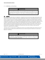
WARNING
This detector helps monitor for the presence and concentration level of a certain specified
airborne gas. Misuse may produce an inaccurate reading, which means that higher levels of the
gas being monitored may be present and could result in overexposure and cause serious injury or
death. For proper use, see supervisor or User manual, or contact Technical Support at 1-844-325-
3050.
3.1 Location
Mounting height will be dependent on the application. For applications with COP2P tanks, mount height should be about one foot
above the floor. For indoor air quality mount detector at breathing level, about 5 feet (1.5 meters) above the floor on a wall or
column in a central area where air movement is generally good. The unit, on average, can cover between 900 sq. ft. (83.62 sq.
meters) and 5000 sq. ft. (464.51 sq. meters) depending on the application. Applications with CO2 tanks, spacing near the tanks
should be closer to the 900 sq. ft. For indoor air quality and purposefully enriched areas, such as greenhouses, spacing can be up
to 5000 sq. ft. When determining the coverage area for each application, keep in mind that each application is going to be
different and needs to be evaluated to determine the number of detectors required to ensure proper coverage. Some of the
factors that affect the coverage area are application type, personnel work areas and movement, room size, air movement,
potential threat, mounting location, along with other site-specific factors that must be considered. Please check local
regulations or requirements prior to installation.
The CD-6G mounts on a 4x4 electrical box supplied by the contractor. Do not install the CD-6G inside another box unless it has
good air flow through it. DO NOT mount the CD-6G where the normal ambient temperature is below 32°F or exceeds 122°F
(below 0°C or above 50°C).
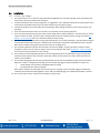
WARNING
High voltage terminals (120/240 VAC) are located within this detector, presenting a hazard to
service technicians. Only qualified technicians should open the detector case and service the
internal circuits. Ensure power is de-energized from the detector relays prior to servicing the unit.
Failure to do so may result in electrical shock.

Macurco CD-6G Operation Manual
REV – 1.0.1 [34-2900-0510-9 ] 9 | Page
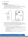
3.2 Installation
3.2.1 6-Series Low Voltage
1. The CD-6G mounts on a 4” square (or 4x4) electrical box supplied by the contractor. DO NOT mount the CD-6G inside
another box, unless it has good air flow through it.
2. Connect the CD-6G to Class 2 power supply only. It is suggested to use a dedicated transformer for powering the unit or
units because of possible interferences from other devices on the same power supply.
3. Connect the CD-6G to the control cables with terminal plugs. When making connections, make sure the power is de-
energized.
4. There are two terminals for Power: 12 to 24 VAC or 12 to 32 VDC, with no polarity preference.
5. There are two terminals for the dry alarm relay contacts, again with no polarity preference. The alarm relay can switch
up to 0.5 A 120 V, or 60 VA. The alarm relay is activated if gas reaches or exceeds the alarm settings. See section 31TU4.5
Default – Factory SettingsU31T of this User manual for details on relay settings.
6. The alarm relay can be configured to normally open (default) (N.O.) or normally closed (N.C.) and will activate if the gas
concentration exceeds alarm set point. It will deactivate once the gas concentration drops below the alarm set point.
Note that the “disable” setting will cause the alarm relay not to engage at all.
7. The dry contact, SPDT fan relay has three terminals. The common (COM.), normally open (N.O.) and the normally
closed (N.C.) contact. The fan relay can switch up to 5.0 A up to 240 VAC. See section 31T4.5 Default – Factory Settings31T of
these User Instructions for details on relay settings.
8. The Fan Relay can be configured for latching or non-latching (default) when activated (when the gas concentration
exceeds fan relay setpoint). Once latched in, power will need to be interrupted or the “TEST” button pressed to un-
latch the relay condition.
9. The Fan Relay will engage if the fan setting Carbon Dioxide concentration is exceeded for longer than the Fan Relay
Delay time. Unless it is configured for latching, the fan relay will disengage once both conditions have been met:
• Carbon Dioxide concentration has dropped below fan setting.
• Fan Relay Runtime has been exceeded.
Note that the “disable” fan setting will cause the fan relay to not engage. The fan relay will engage in trouble fault
condition (if the Trouble Fan Setting Option is set to “ON”) and will disengage once trouble fault condition is cleared.
10. The Current Loop is 4 mA in clean air and 4-20 mA for 0-5.0% vol COP2

Macurco CD-6G Operation Manual
REV – 1.0.1 [34-2900-0510-9 ] 10 | Page
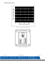
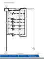
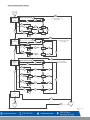
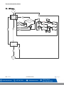
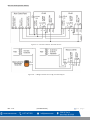
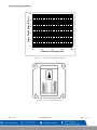
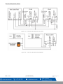
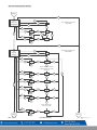
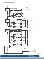
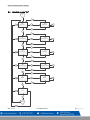
Figure 3-1 6 – Series 4-20 mA Output diagram
Figure 3-2 6 – Series Rear View
0
1
2
3
4
5
4 8 12 16 20
Carbon Dioxide Reading (% vol)
4-20mA Current Output (mA)

Macurco CD-6G Operation Manual
REV – 1.0.1 [34-2900-0510-9 ] 11 | Page
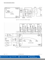
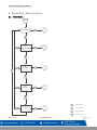
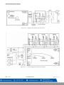
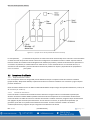
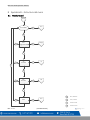
Figure 3-3 6 – Series typical installation diagram
Figure 3-4 – 6 – Series Multiple Device diagram

Macurco CD-6G Operation Manual
REV – 1.0.1 [34-2900-0510-9 ] 12 | Page
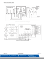
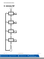
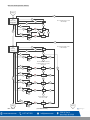
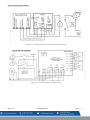
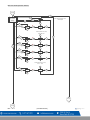
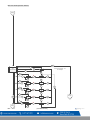
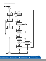
Figure 3-5 6 – Series Alarm Control Panel diagram
Figure 3-6 6 – Series DVP-120 Control Panel

Macurco CD-6G Operation Manual
REV – 1.0.1 [34-2900-0510-9 ] 13 | Page
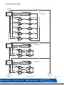
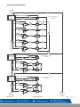
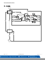
Figure 3-7 6 – Series Alternate Alarm Panel
Figure 3-8 -- CD-6G Horn & Strobe Combo Wiring

Macurco CD-6G Operation Manual
REV – 1.0.1 [34-2900-0510-9 ] 14 | Page
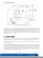
Figure 3-9 -- CD-6G Example of possible mounting location
In this application (31TFigure 3-7 6-Series Alternate Alarm Panel31T) the Fan or primary relay is used as a low-level alarm relay. The
Alarm or secondary relay is used as a supervisory relay when utilized in the normally closed configuration. The CD-6G monitors
all critical functions of the unit through software diagnostics that continually test and verify its operations. If a problem is found,
the unit will switch to a fail-safe/error mode or trouble condition. In this error mode, the Fan* and Alarm relays will be activated
indicating the trouble condition at the panel and the CD-6G display will flash the error. See section 31T4.5.11 Trouble Fan Setting –
“tFS”31T for options.
3.3 Wiring Connections
3.3.1 6-Series Low Voltage
With an exception of the safety ground, all field wiring is completed via modular connectors (provided). After wiring, simply plug
the modular connectors into the matching connectors on the back side of the detector.
NOTE: 22 to 12 AWG wire shall be used. Wire used shall meet the temperature range of the detector i.e., 32°F to 122° F (0°C to
50°C).
3.3.1.1 Power Connection
Connect the CD-6G to Class 2 power supply only. It is suggested to use a separate transformer for powering the unit or units
because of possible interferences from other devices on the same power supply. Connect the CD-6G to the control cables with
terminal plugs. When making connections, make sure the power is off. There are two terminals for Power: 12 to 24 VAC or 12 to
32 VDC, with no polarity preference ensure that the wire cannot be easily pulled from the connector. Plug the modular
connection into the Fan/Power connection and ensure that it latches into the header properly.

Macurco CD-6G Operation Manual
REV – 1.0.1 [34-2900-0510-9 ] 15 | Page
3.3.1.2 Fan Relay Connection
All the SPDT Fan relay terminals are available at the Fan/Power modular connector. Each fan relay terminal normally open,
common, and normally closed (NO, COM, and NC) can accommodate a wire size 12 to 24 AWG. To install the wiring for the
relays, disconnect the connectors from the header. Strip the insulation off each wire back approximately ¼ inch (6.5 mm), insert
the bare wire into the terminal and tighten the screw clamp. Ensure that the wire cannot easily be pulled from the connector.
Plug the modular connection into the Fan/Power connection and ensure that it latches into the header properly.
3.3.1.3 Alarm Relay Connection
The external alarm connections (A and B) are available at the Alarm modular connector. There is no polarity for these
connections. To install the wiring for the alarm contacts, disconnect the connector from the header on the detector. Strip the
insulation of each wire back approximately 1/4 in. (6.5 mm), insert the bare wire into the terminal and tighten the screw clamp.
Ensure that the wire cannot easily be pulled from the connector. When the wires are connected seat the modular connector
into the header ensuring that the latch engages.
3.3.1.4 4-20 mA Output diagram
The positive and negative 4-20mA signal connections (+ and -) are available at the 4-20mA modular connector, a 2-position
connector. To install the wiring for the 4-20 mA contacts, disconnect the connector from the header on the detector. Strip the
insulation of each wire back approximately 1/4 in. (6.5 mm), insert the bare wire into the terminal and tighten the screw clamp.
Ensure that the wire cannot easily be pulled from the connector. When the wires are connected seat the modular connector
into the header ensuring that the latch engages.
42TNote42T: The 4-20mA current loop outputs may be used with the Macurco DVP-120 family and the DVP-1200 control panel or other
systems. The 4-20mA signal connections to detectors should be size AWG18 (minimum) for short runs. Refer to the table for
recommended wire gauges. Do not bundle detector 4-20mA signal connections with AC power cables to prevent electrical
interference. If AC power connections must be bundled with the detector 4-20mA signal cables, the signal connections should
be made with a twisted pair of the appropriate gauge, with an overall foil and braid shield. All shields should be terminated at
the DVP-120 or DVP-1200 end of the cable only. A ground stud is provided near the bottom left corner of the DVP-120 or DVP-
1200 panel.

Macurco CD-6G Operation Manual
REV – 1.0.1 [34-2900-0510-9 ] 16 | Page
4 Operations
1. With the display function turned “On”, the CD-6G will show the current concentration of COP2P ppm in the air. Normal
outdoor concentration ranges between 0.03-0.04% vol . When the COP2P concentration reaches the Fan Relay setting
(0.2% vol. , for example) the display will flash back and forth between “FAn” and “current gas reading”. With the
display function turned “Off”, the display does not show the COP2P concentration but will show “FAn” as long as the fan
relay is activated.
2. With the display function turned “On” and the COP2P concentration reaching the Alarm Relay setting, (0.4% vol., for
example) the display will flash back and forth between “ALr” and “current gas reading”. The buzzer will sound
indicating “Alarm” if the buzzer is turned “On”. With the display function turned off the display does not show the COP2P
concentration but will show “ALr” when the Alarm relay is activated.
3. With the 4-20 mA function turned “On” and the COP2P concentration climbing, the 4-20 mA signal will ramp up
corresponding to the concentration (0-5.00% vol. for example). The display will show “FAn” and “ALr” and sound as
outlined above.
4.1 Power up
The CD-6G cycles through an internal self-test cycle for the first minute that it is powered. The unit will execute the test cycle
any time power is dropped and reapplied (i.e. power failure). During the self-test cycle, the unit will display the firmware version
number, then count down from 60 to 0 (if the display setting is “On”) and finally go into normal operation. The alarm relay will
be activated for 10 seconds and the fan relay for 60 seconds during the power-up cycle unless the “Power Up Test” (PUt) option
is OFF. The indicator light (LED) will flash green during the self-test cycle. At the end of the 1-minute cycle, the unit will take its
first sample of the air and the indicator light will turn solid green.
4.2 Display turned “On”
Clean Air – With the display function turned “On”, the CD-6G will show the current concentration of COP2P ppm.
Note: COP2P in “clean air” will not show 0 as normal atmospheric COP2P levels are between 0.03% vol. or 0.04% vol..
Fan level – When the COP2P concentration reaches the Fan Relay setting (0.20% vol, for example) the display will flash back and
forth between “FAn” and “0.02” (or current gas reading).
Alarm level – With the display function turned “On” and the COP2P concentration reaching the Alarm Relay setting, (0.4% vol. , for
example) the display will flash back and forth between “ALr” and “current gas reading”. The buzzer will sound indicating “Alarm”
if the buzzer is turned “On”.
Trouble – With the display function turned “On” and the device is in a trouble state, the display will display the “t” Error code
(t01 for example). If the Trouble Fan Setting is enabled, the Fan relay will switch activating the relay. See section 31T5.1.2 “t” Error
Codes31T and section 31T4.5.11 Trouble Fan Setting – “tFS”.31T
4.3 Display turned “Off”
Clean Air – With the display function turned” Off”, the display does not show the COP2P concentration. Only the Power indicator
light on will be on.
Fan Level – When the CO2 concentration reaches the Fan Relay setting (0.2% vol., for example) the display will flash back and
forth between “FAn” and “blank” as long as the fan relay is enabled. This appears as slowly flashing “FAn”.
Alarm Level – With the display function turned off the display does not show the COP2P concentration but will show “ALr” when
the Alarm relay is activated.
Trouble – With the display function turned “On” and the device is in a trouble state, the display will display the “t” Error code
(t01 for example). If the Trouble Fan Setting is enabled, the Fan relay will switch activating the relay. See section 31T5.1.2 “t” Error
Codes31T and section 31T4.5.11 Trouble Fan Setting – “tFS”.31T

Macurco CD-6G Operation Manual
REV – 1.0.1 [34-2900-0510-9 ] 17 | Page
4.4 4-20mA Loop
Clean Air – With the 4-20 mA function turned “On” and the current concentration of COP2P ppm, the 4-20mA loop will output a
mA reading equivalent to the current gas reading of the detector.
Fan Level – With the 4-20 mA function turned “On” and the current concentration of COP2P ppm detected is at or greater than the
Fan Relay Setting (Frs), the 4-20mA loop will output between 4 mA and 20 mA depending on the current concentration of COP2P.
See figure 31T3-1 4-20 mA Output diagram31T or figure 331T -9 12-Series 4-20 mA Output diagram31T
Alarm Level – With the 4-20 mA function turned “On” and the current concentration of COP2P ppm detected is at or greater than
the Alarm Relay Setting (Ars), the 4-20mA loop will output between 4 mA and 20 mA depending on the current concentration of
COP2P. See figure 31T3-1 4-20 mA Output diagram31T or 31Tfigure 3-9 12-Series 4-20 mA Output diagram31T
Trouble – With the 4-20 mA function turned “On” and Trouble Fan Setting enabled. The 4-20mA loop will output less than 4 mA
or greater than 20 mA depending on the Trouble condition. See section 31T5.1 On-Board Diagnostics31T.
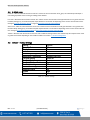
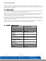
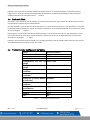
4.5 Default – Factory Settings
Setting:
Default:
Power Up Test
Off
Display
On
Buzzer
On
Alarm Relay Setting
0.50% vol.
Alarm Relay Configuration
Normally Open (NO)
Fan Relay Setting
0.20% vol.
Fan Relay Delay
3 minutes
Fan Relay Minimum Runtime
0 minutes
Fan Relay Latching
Off
Trouble Fan Setting
Off
Awareness Alarm
Off
4-20mA
bAS
CAL
diS
Table 4-1 – Default settings

Macurco CD-6G Operation Manual
REV – 1.0.1 [34-2900-0510-9 ] 18 | Page
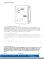
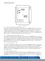
Figure 4-1 – Board View
4.5.1 Selecting Default Configuration – “dEF”
To select the Default Configuration, in normal mode, push the Next button to get to “Con” or the Configuration menu. Then
push the Enter button to enter the Con menu. The first selection is the “dEF” or Default setting. Push Enter. If it is already in
Default configuration, there will be no action. If it is not already in Default configuration, “nO” will be displayed. Push Next to
change it to “YES” (flashing) then push Enter to confirm the change (solid) and push Enter again to return to “dEF” in the con
menu. Push Next until “End” is displayed then push Enter to get back to normal operation.
4.5.2 Power-Up Test Setting – “PUt”
To select the Power Up Test Configuration, in normal mode, push the Next button to get to “Con” or the Configuration menu.
Then push the Enter button to enter the Con menu. Then push the Next button to get to the second selection “PUt” or Power
Up Test setting. Push Enter. If the test is “On” push Next to turn it “OFF” (flashing) then push Enter to confirm the change (solid)
and push Enter again to return to “PUt” in the Con menu. Push Next until “End” is displayed then push Enter to get back to
normal operation.
4.5.3 Display Setting – “dSP”
To select the Display Configuration, in normal mode, push the Next button to get to “Con” or the Configuration menu. Then
push the Enter button to enter the Con menu. Then push the Next button to get to the third selection “dSP” or Display setting.
Push Enter. If the display is “On” push Next to turn it “OFF” (flashing) then push Enter to confirm the change (solid) and push
Enter again to return to “dSP” in the Con menu. Push Next until “End” is displayed then push Enter to get back to normal
operation.
4.5.4 Buzzer Setting – “bUZ”
To select the Buzzer Configuration, in normal mode, push the Next button to get to “Con” or the Configuration menu. Then push
the Enter button to enter the Con menu. The fourth selection is the “bUZ” or Buzzer setting. Push Next twice to get to “bUZ”
then Enter. If the display is “On” push Next to turn it “OFF” (flashing) then push Enter to confirm the change (solid) and push
Enter again to return to “bUZ” in the Con menu. Push Next until “End” is displayed then push Enter to get back to normal
operation.

Macurco CD-6G Operation Manual
REV – 1.0.1 [34-2900-0510-9 ] 19 | Page
4.5.5 Alarm Relay Setting – “ArS”
To select the Alarm Relay Setting, in normal mode, push the Next button to get to “Con” or the Configuration menu. Then push
the Enter button to enter the Con menu. The fifth selection is the “ArS” or Alarm Relay Setting. Push Next three times to get to
“ArS” then Enter. If the display is “OFF, 0.09, 0.1, 0.11, 0.12, 0.13, 0.14, 0.15, 0.16, 0.17, 0.18, 0.19, 0.2, 0.21, 0.22, 0.23, 0.24,
0.25, 0.50 (default), 1.00, 1.50, 2.00, 2.50, 3.00, 3.50, 4.00% vol. (flashing) then push Enter to confirm the change (solid) and
push Enter again to return to “ArS” in the Con menu. Push Next until “End” is displayed then push Enter to get back to normal
operation.
4.5.6 Alarm Relay Configuration – “Arc”
To select the Alarm Relay Configuration, in normal mode, push the Next button to get to “Con” or the Configuration menu. Then
push the Enter button to enter the Con menu. The sixth selection is the “Arc” or Alarm Relay Configuration. Push Next four
times to get to “Arc” then Enter. If the relay is “nO” (normally open) push Next to turn it to “nC” (flashing) then push Enter to
confirm the change (solid) and push Enter again to return to “Arc” in the Con menu. Push Next until “End” is displayed then
push Enter to get back to normal operation.
4.5.7 Fan Relay Setting – “FrS”
To select the Fan Relay setting, in normal mode, push the Next button to get to “Con” or the Configuration menu. Then push the
Enter button to enter the Con menu. The seventh selection is the “FrS” or Fan Relay setting. Push Next five times to get to “FrS”
then Enter. If the fan relay is OFF, 0.09, 0.1, 0.11, 0.12, 0.13, 0.14, 0.15, 0.16, 0.17, 0.18, 0.19, 0.2 (default), 0.21, 0.22, 0.23,
0.24, 0.25, 0.50, 1.00, 1.50, 2.00, 2.50, 3.00, 3.50, 4.00 (flashing) then push Enter to confirm the change (solid) and push Enter
again to return to “FrS” in the Con menu. Push Next until “End” is displayed then push Enter to get back to normal operation.
4.5.8 Fan Relay Delay Setting – “Frd”
To select the Fan Relay Delay setting, in normal mode, push the Next button to get to “Con” or the Configuration menu. Then
push the Enter button to enter the Con menu. The eighth selection is the “Frd” or Fan Relay Delay. Push Next six times to get to
“Frd” then Enter. If the delay is “0” (disabled) push Next to change it to 1, 3, 5, or 10 minutes (flashing) then push Enter to
confirm the change (solid) and push Enter again to return to “Frd” in the Con menu. Push Next until “End” is displayed then
push Enter to get back to normal operation.
4.5.9 Fan Relay Minimum Runtime Setting – “Frr”
To select the Fan Relay Minimum Runtime setting, in normal mode, push the Next button to get to “Con” or the Configuration
menu. Then push the Enter button to enter the Con menu. The ninth selection is the “Frr” or Fan Minimum Run Time. Push Next
seven times to get to “Frr” then Enter. If the runtime is “0” (disabled) push Next to change it to 3, 5, 10 or 15 minutes (flashing)
then push Enter to confirm the change (solid) and push Enter again to return to “Frr” in the Con menu. Push Next until “End” is
displayed then push Enter to get back to normal operation.
4.5.10 Fan Relay Latching Setting – “FrL”
To select the Fan Relay Latching Option, in normal mode, push the Next button to get to “Con” or the Configuration menu. Then
push the Enter button to enter the Con menu. The tenth selection is the “FrL” or Fan Relay Latching Option. Push Next nine
times to get to “FrL” then Enter. If latching is “OFF” push Next to turn it to “ON” (flashing) then push Enter to confirm the
change (solid) and push Enter again to return to “FrL” in the Con menu. Push Next until “End” is displayed then push Enter to
get back to normal operation.
4.5.11 Trouble Fan Setting – “tFS”
To select the Trouble Fan Setting Option, in normal mode, push the Next button to get to “Con” or the Configuration menu.
Then push the Enter button to enter the Con menu. The eleventh selection is the “tFS” or Trouble Fan Setting Option. Push Next
ten times to get to “tFS” then Enter. If Trouble Fan Setting is “OFF” push Next to turn it to “ON” (flashing) then push Enter to
confirm the change (solid) and push Enter again to return to “tFS” in the Con menu. Push Next until “End” is displayed then
push Enter to get back to normal operation.

Macurco CD-6G Operation Manual
REV – 1.0.1 [34-2900-0510-9 ] 20 | Page
4.5.12 Awareness Alarm – “AAS”
The Awareness Alarm is set at 0.50% vol and is not user configurable. When the gas reading is equal to or greater than 0.50%
vol, the unit indicates an Awareness Alarm. During an Awareness Alarm, the buzzer will beep every 60 seconds. If the display is
ON, the display will flash the gas reading. Awareness Alarm can be enabled or disable with this configuration menu. To enable or
disable this alarm, in normal more, push the Next button to get to the "Con" or the Configuration menu. Then push the Enter
button to enter the Con menu. Push Next eleven times to get to "AAS" or Awareness Alarm menu. Press Enter to enter the
mode. Press the Next button to set the value to "On" or "OFF". Once the desired value is flashing on the display, press Enter to
save the setting. Press Next to take you to "End". Press Enter to return to normal operation.
4.5.13 4-20mA Output setting – “420”
To select the 4-20mA Output Option, in normal mode, push the Next button to get to “Con” or the Configuration menu. Then
push the Enter button to enter the Con menu. The twelfth selection is the “420” or 4-20mA Output Option. Push Next eleven
times to get to “420” then Enter. If the 4-20mA is “bAS” push Next to turn it to “EnH” (flashing) and push Next one more time to
turn it to “OFF” (flashing). Then push Enter to confirm the change (solid) and push Enter again to return to “420” in the Con
menu. Push Next until “End” is displayed then push Enter to get back to normal operation.
NOTE: CD-6G will transmit information about calibration period to Macurco Control Panel (via 4-20 mA output) only when 4-
20mA output setting is set to ‘EnH’.
4.5.14 Calibration Period Settings – “CAL”
Value selected in Calibration Period settings is number of months. CM-xx indicates a “calibration due” when it is within 1 month
of calibration period, and “calibration overdue” when detector has reached or exceeded calibration period. Calibration Period
Settings cannot be changed if CD-6G is indicating “calibration due” or “calibration overdue”.
To select the Calibration Period Option, in normal mode, push the Next button to get to “Con” or the Configuration menu. Then
push the Enter button to enter the Con menu. The thirteenth selection is “CAL” or Calibration Period setting. Push Next twelve
time to get to “CAL” then push Enter. Default setting is “dIS”. Push Next to change it to 3, 6, 12 or 24 (flashing) then push Enter
to confirm the change (solid). Then push Enter again to return to “CAL” in the Con menu. Push Next until “End” is displayed then
push Enter to get back to normal operation.

Macurco CD-6G Operation Manual
REV – 1.0.1 [34-2900-0510-9 ] 21 | Page
5 Troubleshooting
5.1 On-Board Diagnostics
The CD-6G monitors all critical functions of the unit through software diagnostics that continuously test and verify unit
operations. If a problem is found, the unit will switch to a fail-safe/error mode or trouble condition. In this error mode, the
Alarm relay will be activated, the 4-20 mA current loop will go to 24 mA, the unit will display the error code, the green status
indicator LED light will flash, and the buzzer will chirp intermittently. The Fan relay will also engage if the Trouble Fan Setting
Option is set to “ON”. This is a safety precaution. To clear this mode, simply turn off power to the unit for a few seconds or push
the ENTER/TEST switch (inside the unit). This will cause the unit to restart the 1-minute self-test cycle.
5.1.1 4-20mA troubleshooting.
• 0 mA is most likely a connection problem.
• 4-20 mA is normal gas reading range (0-5.00 % vol)
• 24 mA indicates a Trouble condition.
• 1 mA indicates Calibration Overdue (if 4-20mA is configured to ‘EnH’)
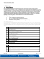
5.1.2 “t” Error Codes
The CD-6G will display trouble codes indicated by alternating every second “t XX” and “tYYY”. E.g., if sensor displays “t 20”
alternating with “t000” then referring “t XX” table it indicates the sensor reading is out of range and in “tYYY” all the fields are 0
so there is not any trouble occurring from “tYYY” table.
t XX
t 01
Sensor Fatal Error
t 02
Sensor Offset Regulation Error
t 04
Sensor Algorithm Error
t 08
Sensor Output Error
t 10
Sensor Self Diagnostic Error
t 20
Sensor Out of Range Error
t 40
Sensor Memory Error
t 80
Calibration Overdue
tYYY
t001
Missing Sensor
t002
At each power-up it checks if that ABC is disabled. If it is not disabled it will try to set it to disable. If it
fails it will trigger trouble t002.
t004
EEPROM bad checksum.
t008
Modbus communication error (during normal operation).
t010
Bad EEPROM
t020
Bad Factory or Field calibration.
t040
Never Factory calibrated.
t080
Bad pressure during factory calibration
t100
Under range. Reading is under -100 ppm for more than 15 seconds
t200
Sensor Expired
t400
Trouble Pressure Sensor
t800
Board not tested
La page est en cours de chargement...
La page est en cours de chargement...
La page est en cours de chargement...
La page est en cours de chargement...
La page est en cours de chargement...
La page est en cours de chargement...
La page est en cours de chargement...
La page est en cours de chargement...
La page est en cours de chargement...
La page est en cours de chargement...
La page est en cours de chargement...
La page est en cours de chargement...
La page est en cours de chargement...
La page est en cours de chargement...
La page est en cours de chargement...
La page est en cours de chargement...
La page est en cours de chargement...
La page est en cours de chargement...
La page est en cours de chargement...
La page est en cours de chargement...
La page est en cours de chargement...
La page est en cours de chargement...
La page est en cours de chargement...
La page est en cours de chargement...
La page est en cours de chargement...
La page est en cours de chargement...
La page est en cours de chargement...
La page est en cours de chargement...
La page est en cours de chargement...
La page est en cours de chargement...
La page est en cours de chargement...
La page est en cours de chargement...
La page est en cours de chargement...
La page est en cours de chargement...
La page est en cours de chargement...
La page est en cours de chargement...
La page est en cours de chargement...
La page est en cours de chargement...
La page est en cours de chargement...
La page est en cours de chargement...
La page est en cours de chargement...
La page est en cours de chargement...
La page est en cours de chargement...
La page est en cours de chargement...
La page est en cours de chargement...
La page est en cours de chargement...
La page est en cours de chargement...
La page est en cours de chargement...
La page est en cours de chargement...
La page est en cours de chargement...
La page est en cours de chargement...
La page est en cours de chargement...
La page est en cours de chargement...
La page est en cours de chargement...
La page est en cours de chargement...
La page est en cours de chargement...
La page est en cours de chargement...
La page est en cours de chargement...
La page est en cours de chargement...
La page est en cours de chargement...
La page est en cours de chargement...
La page est en cours de chargement...
La page est en cours de chargement...
La page est en cours de chargement...
La page est en cours de chargement...
La page est en cours de chargement...
La page est en cours de chargement...
La page est en cours de chargement...
La page est en cours de chargement...
La page est en cours de chargement...
La page est en cours de chargement...
La page est en cours de chargement...
La page est en cours de chargement...
La page est en cours de chargement...
La page est en cours de chargement...
La page est en cours de chargement...
La page est en cours de chargement...
La page est en cours de chargement...
La page est en cours de chargement...
La page est en cours de chargement...
La page est en cours de chargement...
La page est en cours de chargement...
La page est en cours de chargement...
La page est en cours de chargement...
La page est en cours de chargement...
La page est en cours de chargement...
La page est en cours de chargement...
La page est en cours de chargement...
La page est en cours de chargement...
La page est en cours de chargement...
La page est en cours de chargement...
La page est en cours de chargement...
La page est en cours de chargement...
La page est en cours de chargement...
La page est en cours de chargement...
La page est en cours de chargement...
La page est en cours de chargement...
La page est en cours de chargement...
La page est en cours de chargement...
La page est en cours de chargement...
La page est en cours de chargement...
La page est en cours de chargement...
-
 1
1
-
 2
2
-
 3
3
-
 4
4
-
 5
5
-
 6
6
-
 7
7
-
 8
8
-
 9
9
-
 10
10
-
 11
11
-
 12
12
-
 13
13
-
 14
14
-
 15
15
-
 16
16
-
 17
17
-
 18
18
-
 19
19
-
 20
20
-
 21
21
-
 22
22
-
 23
23
-
 24
24
-
 25
25
-
 26
26
-
 27
27
-
 28
28
-
 29
29
-
 30
30
-
 31
31
-
 32
32
-
 33
33
-
 34
34
-
 35
35
-
 36
36
-
 37
37
-
 38
38
-
 39
39
-
 40
40
-
 41
41
-
 42
42
-
 43
43
-
 44
44
-
 45
45
-
 46
46
-
 47
47
-
 48
48
-
 49
49
-
 50
50
-
 51
51
-
 52
52
-
 53
53
-
 54
54
-
 55
55
-
 56
56
-
 57
57
-
 58
58
-
 59
59
-
 60
60
-
 61
61
-
 62
62
-
 63
63
-
 64
64
-
 65
65
-
 66
66
-
 67
67
-
 68
68
-
 69
69
-
 70
70
-
 71
71
-
 72
72
-
 73
73
-
 74
74
-
 75
75
-
 76
76
-
 77
77
-
 78
78
-
 79
79
-
 80
80
-
 81
81
-
 82
82
-
 83
83
-
 84
84
-
 85
85
-
 86
86
-
 87
87
-
 88
88
-
 89
89
-
 90
90
-
 91
91
-
 92
92
-
 93
93
-
 94
94
-
 95
95
-
 96
96
-
 97
97
-
 98
98
-
 99
99
-
 100
100
-
 101
101
-
 102
102
-
 103
103
-
 104
104
-
 105
105
-
 106
106
-
 107
107
-
 108
108
-
 109
109
-
 110
110
-
 111
111
-
 112
112
-
 113
113
-
 114
114
-
 115
115
-
 116
116
-
 117
117
-
 118
118
-
 119
119
-
 120
120
-
 121
121
-
 122
122


dans d''autres langues
- English: Macurco CD-6G User manual
- español: Macurco CD-6G Manual de usuario
Documents connexes
Autres documents
-
 Co2meter Remote CO2 Storage Safety 3 Alarm Manuel utilisateur
-
Bradford White BMGH1600 Manuel utilisateur
-
Comelit 47RT282EC-H Manuel utilisateur
-
Wacker Neuson Arctic Bear XHD Manuel utilisateur
-
Raypak XVers L 406L-856L Type H Mode d'emploi
-
 Hach Lange astroTOC Basic User Manual
-
Trox X-CUBE X2 Mode d'emploi
-
Bradford White BMT2V0200NACK5XC Manuel utilisateur

