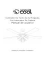
commercial cool CCF45P20 Manuel utilisateur
- Catégorie
- Ventilateurs ménagers
- Taper
- Manuel utilisateur

42 in. Ceiling Fan with Pull Chain
User Manual
MODEL CCF45P10; CCF45P30

Page 2
ENGLISH
CONTENTS
SAFETY INFORMATION
Important Safety Instructions ..........................................................................................................................................3-4
SET UP & USE
Parts & Features ....................................................................................................................................................................... 5
Installation Instructions ....................................................................................................................................................6-7
Installation Steps ................................................................................................................................................................ 8-14
Operation Instructions .........................................................................................................................................................15
TROUBLESHOOTING & WARRANTY
Before You Call For Service ................................................................................................................................................16
Troubleshooting ..................................................................................................................................................................17-18
Limited Warranty ......................................................................................................................................................................19
Thank you for purchasing our
Commercial Cool product. This
easy-to-use manual will guide you
in getting the best use of your fan.
Remember to record the model
and serial numbers. They are on a
label on the rear.
Staple your receipt to your manual.
You will need it to obtain warranty service.
Model number
Serial number
Date of purchase
PRODUCT REGISTRATION

Page 3
ENGLISH
IMPORTANT SAFETY INSTRUCTIONS
1. READ ALL INSTRUCTIONS BEFORE USE
2. To avoid possible electric shock, turn o the electricity at the main fuse box or
circuit panel before you begin the fan installation, before servicing the fan or
installing accessories.
3. Read all instructions and safety information carefully before installing your fan and
save these instructions.
4. Make sure all electrical connections comply with local codes or ordinances and
the National Electrical Code. If you are unfamiliar with electric wiring, please use a
qualified and licensed electrician.
5. Make sure you have a location selected for your fan that allows clear space for the
blades to rotate, and at least seven (7) feet of clearance between the floor and
the fan blades. The fan should be mounted at least thirty (30) inches from walls or
other upright structures.
6. WARNING: The outlet box and ceiling support joist used must be securely
mounted and capable of supporting at least 50 pounds. To reduce the risk of fire,
electric shock or personal injury, mount to the outlet box marked acceptable for
fan supported and use mounting screws provided with the outlet box. The box
must be supported directly by the building structure.
7. WARNING: To reduce the risk of fire, electric shock or personal injury, mount
to outlet box marked “acceptable for fan support” and use mounting screws
provided with the outlet box. Most outlet boxes commonly used for the support of
lighting fixtures are not acceptable for fan support and may need to be replaced.
Consult a qualified electrician if in doubt.
8. Electrical diagrams are for reference only. Light kits that are not packed with the
fan must be UL listed and marked suitable for use with the model fan you are
installing. Switches must be UL general use switches. Refer to the instructions
packaged with the light kits and switches for proper assembly.
9. After installation is complete, check that all connections are secure.
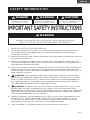
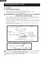
SAFETY INFORMATION
DANGER
DANGER - Immediate hazards
which WILL result in severe
personal injury or death
WARNING
WARNING - Hazards or unsafe
practices which COULD result in
severe personal injury or death
CAUTION
CAUTION - Hazards or unsafe
practices which COULD result in
minor personal injury
WARNING
When using electrical appliances, basic safety precautions should always be
followed to reduce the risk of re, electric shock and personal injury
:
READ ALL INSTRUCTIONS BEFORE USING THE PRODUCT

Page 4
ENGLISH
10. After making electrical connections, spliced conductors should be turned upward
and pushed carefully up into outlet box. The wires should be spread apart with
the grounded conductor and the equipment-grounding conductor on one side of
the outlet box.
11. WARNING: To reduce the risk of electrical shock and fire, do not use this fan
with any solid-state fan speed control device or rheostat.
12. Do not operate the reverse switch until the fan has come to a complete stop.
13. Do not insert anything into the fan blades while they are rotating.
14. WARNING: To reduce the risk of personal injury do not bend the blade
brackets (also referred to as “flanges”) during assembly or after installation. Do
not insert objects in the path of the blades.
15. To avoid personal injury or damage to the fan and other items, caution must be
used when working around or cleaning the fan.
16. Do not use water or detergent when cleaning the fan or fan blades, A dry dust
cloth or lightly dampened cloth will be suitable for most cleaning.
NOTE: The important safety precautions and instructions appearing in the manual
are not meant to cover all possible conditions and situations that may occur. It
must be understood that common sense and caution are necessary factors in
the installation and operation of this fan.
NOTE: This product is not intended for use by persons (including children) with
reduced physical, sensory or mental capabilities or are impaired, or lack of
experience or knowledge, unless such persons are supervised or trained to
operate the appliance by a person responsible for their safety.
NOTE: Children should be supervised to ensure that they do not use appliances
as a toy.
NOTE: You must install a switch or circuit breaker that disconnects l poles power at
least 3 mm between each pole.
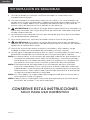
SAVE THESE INSTRUCTIONS
HOUSEHOLD USE ONLY
SAFETY INFORMATION

Page 5
ENGLISH
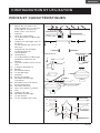
SET UP & USE
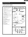
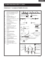
PARTS & FEATURES
1. Wooden Joist
2. Approved (CSA for Canada
and UL for U.S.) ceiling fan
box (not provided)
3. Ceiling
4. Rubber Gasket
5. Screws & Lock Washers (set
of 4)
6. Mounting Bracket c/w Ground
wire
7. Outlet Box Screws (not
provided)
8. Lock Pin
9. Hemisphere Jam Screw
10. Hemisphere
11. Upper Motor Housing Screws
& Lock Washers
12. Downrod c/w Ground Wire
13. Ceiling Canopy
14. Bolt
15. Motor Assembly
16. Jam Screws
17. Cotter Pin
18. Nut (optional)
19. Lock Washer (optional)
20. Flat Washer (optional)
21. Hex Nut
22. Fibre Washer
23. Fibre Bracket Gasket
24. Blade
25. Blade Bracket
26. Lock Washer
27. Motor Screw
28. Blade Bracket Screws
1.
2.
3.
4.
5. 6.
7. 7.
8.
9.
10.
12.
13.
13.
14.
15.
16.
15.
17.
18.
19.
20.
21.
22.
22.
23.
25.
26.
26.
27.
28.
28.
24.
24.
11.
With Downrod Without Downrod

Page 6
ENGLISH
INSTALLATION INSTRUCTIONS
SET UP & USE
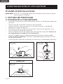
SAFETY PRECAUTIONS:
1. Turn o power at main electrical service box before starting installation.
2. Electrical connections must comply with local code ordinances, national
electrical codes, CEC, NEC and ANSI/NFPA 70.
3. Make sure the installation site you choose allows the fan blades to rotate freely
without any obstructions.
4. When mounting the fan on a ceiling outlet box, use an approved (CSA for
Canada and UL for U.S.) ceiling fan box marked “FOR FAN SUPPORT”. Ensure
the outlet box is securely installed in place and that it is able to support at least
the fan weight.
5. WARNING: To reduce the risk of fire, electric shock, or other personal injury,
mount fan only on an outlet box or supporting system marked acceptable for
fan support of 35 lbs (15.9 kgs) or more and use the mounting screws provided
with the outlet box. Most outlet boxes commonly used for the support of lighting
fixtures are not acceptable and may need to be replaced. Consult a qualified
electrician if in doubt.
6. Total Fan Weight For Reference: 30” Fan is approximately 11.02 lbs;
36” Fan is approximately 13.23 lbs, 42” Fan is approximately 16.53 lbs;
48” Fan is approximately 17.63 lbs, and 52” Fan is approximately 19.84 lbs.
WARNING:
• WARNING: TO REDUCE THE RISK OF FIRE, ELECTRIC SHOCK, OR
PERSONAL INJURY, MOUNT TO OUTLET BOX MARKED ACCEPTABLE FOR
FAN SUPPORT AND USE MOUNTING SCREWS PROVIDED WITH THE OUTLET
BOX.
• Mount with the lowest moving parts at least 7 Feet (2.10 Meters) above floor or
grade level.
• DO NOT operate reversing switch while fan blades are in motion. Fan must be
turned o and rotating blades stopped. When fan blades have stopped, reverse
and speed chain may be pulled to start operation again.

Page 7
ENGLISH
SET UP & USE
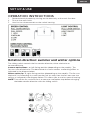
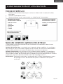
INSTRUCTIONS:
A full internal switching system is used to control the pull chain operated fan and
light. Two pull chains are used; one for turning the light on and o and the other for
controlling fan speed. The fan speed pull chain is marked SPEED on the fan switch
housing for easy identification.
Fan Speed Pull Chain with 4 Options:
1st Pull: High Fan Speed
2nd Pull: Medium Fan Speed
3rd Pull: Low Fan Speed
4th Pull: Fan O
FORWARD/REVERSE FEATURE
This ceiling fan has a Forward/Reverse slide switch. Forward fan blade movement
creates a downdraft for a cooling eect in warm summer days. The reverse fan blade
setting creates an updraft to circulate hot air o the ceiling and back down to the
floor for colder winter days.

Page 8
ENGLISH
SET UP & USE
INSTALLATION STEPS
NOTE: All set screws must be checked and retightened where necessary, before and
after installation.
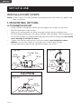
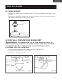
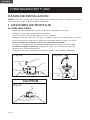
1. MOUNTING OPTION
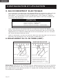
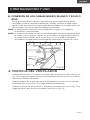
A. DOWNROD MOUNT
• Using a Philips screwdriver, loosen the two upper jam screws on the yoke.
• Position downrod inside canopy.
• Route wires exiting yoke on motor through ceiling canopy and downrod.
• Position downrod/canopy into yoke and align holes between yoke and downrod.
• Insert bolt through the aligned openings between yoke and downrod. Be careful
not to damage or cut the fan wires.
• Tighten flat washer, lock washer, and nut and bolt (not included on some
models). Secure with cotter pin through hole in the end of the bolt.
• Secure downrod in position by tightening upper jam screws.
Bolt
Flat
Washer
Cotter Pin
Yoke
Jam
Screw
Fig.2a
Bolt
Cotter
Flat
Washer
Pin
Fig.2b
Yoke
Jam
Screw
CAUTION
Do not loosen two
lower jam screws
Fig.2c

Page 9
ENGLISH
SET UP & USE
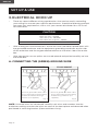
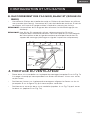
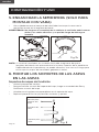
B. FLUSH MOUNT
• Remove the yoke screws and lockwashers which correspond to the holes in the
canopy.
• Position canopy over the holes on motor and secure with the same screws and
lockwashers removed in the previous step.
Fig. 2d
Yoke Screws &
Washers
Canopy
Motor
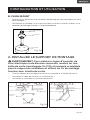
2. INSTALL MOUNTING BRACKET
WARNING: To reduce the risk of fire, electric shock, or
personal injury, mount to UL/CSA listed outlet box marked
acceptable for fan support and use mounting screws
provided with the outlet box.
• Secure mounting bracket and rubber gaskets to outlet box.
• Hang the safety cable onto the J-hook.
• Hang fan on temporary hook.
Fig. 3a Fig. 3b
Wood Joist
Outlet Box
Rubber Gasket Ceiling
Outlet Box Screws
(not provided)
Safety Cable
Canopy
Temporary Hook
Mounting
Bracket

Page 10
ENGLISH
SET UP & USE
• After making the wire connections, ensure the wires should be spread apart with
the grounded conductor and the equipment-grounding conductor on one side
of the outlet box and the ungrounded conductor on the other side of the outlet
box.
• After connection, ensure splices are turned upward and pushed carefully up into
the outlet box.
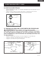
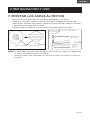
A. CONNECTING THE (GREEN) GROUND WIRE
3. ELECTRICAL HOOK UP
• There are several dierent wiring combinations that can be used in controlling
your ceiling fan to meet your specific requirements. Should the following method
not meet your requirements, call or visit your nearest distributor for a full list of
fan accessories.
CAUTION
Green Wire - GROUND
Black Wire (Fan) - POWER
White Wire (Fan) - COMMON
Red or Blue Wire (Light Kit) - POWER
“SEE SAFETY PRECAUTIONS” ON PAGE #3-4 BEFORE WIRING
Fig. 4 Fig. 5
NOTE: Once the wires are connected, carefully tuck wires and marettes into the
outlet box making sure that the wires are clear of the hemisphere and downrod when
positioned in mounting bracket. (Downrod Mount Only).
Marette Marette
• Connect ground wire from outlet
box to green wire from mounting
bracket and downrod using a
marette (not supplied).
• Connect ground wire from outlet
box to green wire from mounting
bracket using a marette (not
supplied).
DOWNROD MOUNT FLUSH MOUNT

Page 11
ENGLISH
SET UP & USE
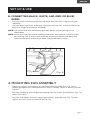
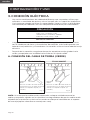
4. MOUNTING FAN ASSEMBLY
• Place two screws and washers on mounting plate (marked B on Fig. 7a on
following page) which correspond with slots in canopy. Screw in loosely, Do Not
Tighten.
• Position canopy to mounting plate aligning slots to screws (marked B on Fig. 7a)
then turn to lock.
• Position and tighten the two screws and washers (marked A on Fig. 7a) then
tighten the two screws (marked B on Fig. 7a).
B. CONNECTING BLACK, WHITE, AND (RED OR BLUE)
WIRES
• Connect white wire from outlet box to white wire from fan using marret (not
supplied).
• Connect black wire from outlet box to black wire from fan, as well as the red or
blue wire using a marret (not included).
NOTE: The red or blue wire connection provides power to the lighting unit (if
applicable).
NOTE: Once wires are connected, carefully tuck wires and marettes into the outlet
box making sure that the wires are clear of the hemisphere and downrod
when positioned in mounting bracket. (Downrod Mount Only).
Fig. 6
White Wire
Black Wire
Red or
Blue Wire

Page 12
ENGLISH
SET UP & USE
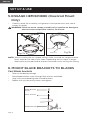
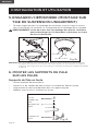
5. ENGAGE HEMISPHERE (Downrod Mount
Only)
• Carefully rotate fan assembly until groove in hemisphere locks over tab of
canopy assembly.
WARNING: Failure to secure canopy assembly to fan could cause damage to
electrical wires and possible shock or fire hazard.
6. MOUNT BLADE BRACKETS TO BLADES
(B)
(B)
(A)
Fig.7a Fig.7b
(A) Washers
Hemisphere
Downrod
Groove
NOTE: When installing fan on sloped ceiling, make sure tab on hanger bracket
faces towards the top of the slope. Depending on the slope, a longer
downrod may be required to prevent fan blades from hitting the ceiling.
Cast Blade brackets
• Take out hardware package.
• Place blade bracket screw through fibre washer and blade.
• Align with corresponding hole in blade bracket.
• Repeat with (2) remaining screws and tighten.
Fig. 8
Blade Bracket
Screw
Fibre Washer
Blade Bracket

Page 13
ENGLISH
SET UP & USE
7. MOUNTING BLADES TO MOTOR
• Take out hardware containing motor screws, lock washers and gaskets.
• Place lock washers over motor screws, position motor screws in blade brackets,
place fibre bracket gaskets over screws and secure to motor.
• Make sure all screws are tightened securely.
Fig. 9a Fig. 9b
Remove Rubber Stops (optional)
Motor
Fibre Bracket
Gasket
Lock Washer
Motor Screw
NOTE: Fan comes with three rubber stops (optional on some models) on motor
for shipping purposes only. Remove stops before running motor or
installing blades to motor.

Page 14
ENGLISH
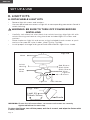
8. LIGHT KITS
A. DETACHABLE LIGHT KITS
• Remove light kit screws and washers.
• Connect polarized connectors of light kit to corresponding connectors found in
switch housing.
WARNING: BE SURE TO TURN OFF POWER BEFORE
INSTALLING
• Carefully tuck electrical wires back into switch housing, align light kit with
switch housing and secure using the three included light kit screws and
washers.
• Place shades on light kit and secure using included thumb screws or push
and turn for pop-o style shades. (See Fig.10a, Fig.10b).
• Install proper wattage and type of bulb identified on light kit or shade.
SET UP & USE
Fig. 10a
Motor
Switch
Housing Red, Blue or
Black Wires
Black, Blue or
Red Wires
Light Kit
Screws
White
Wires
Light Kit Lock Washer
Fig. 10b
Light Kit
Shade
Thumb Screw
WARNING: Ensure that all connections, set screws and screws are securely
tightened before the next step.
To clean the fixture, turn off the power, wait for it to cool, and wipe the fixture with
a clean, soft cloth.

Page 15
ENGLISH
SET UP & USE
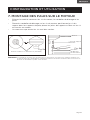
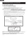
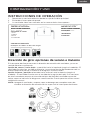
OPERATION INSTRUCTIONS
1. Restore electrical power by turning on the electricity at the main fuse box.
2. Turn on the wall switch.
3. Your fan has three controls on the switch housing.
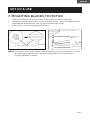
Rotation direction: summer and winter options
The sliding switch controls the fan rotation direction, either clockwise or
counterclockwise.
Summer option/down - or left-facing position (depending on the model) - The
fan runs counterclockwise. The downward air current creates a refreshing eect as
indicated in the diagram below.
Winter option/up- or right-facing position (depending on the model) - The fan runs
clockwise. An ascending air current pushes hot air away from the fan area near the
ceiling, as indicated in the diagram below. This allows you to use less central heating.
NOTE: Turn o the fan, and wait for it to come to a complete stop before changing
the blade rotation direction with the sliding switch.

Page 16
ENGLISH
TROUBLESHOOTING & WARRANTY
BEFORE YOU CALL FOR SERVICE
IF THE UNIT FAILS TO OPERATE:
A) Check to make sure that the unit is plugged in securely. If it is not, remove the
plug from the outlet, wait 10 seconds and plug it in again securely.
B) Check for a blown circuit fuse or a tripped main circuit breaker. If these seem to
be operating properly, test the outlet with another appliance.
IF NONE OF THE ABOVE SOLVES THE PROBLEM, CONTACT A QUALIFIED
TECHNICIAN. DO NOT TRY TO ADJUST OR REPAIR THE PRODUCT YOURSELF.
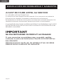
IMPORTANT
DO NOT RETURN THIS PRODUCT TO THE STORE
If you have a problem with this product, please contact the
W Appliance Co. Customer Satisfaction Center at
844-299-0879 or [email protected].
DATED PROOF OF PURCHASE, MODEL # AND SERIAL #
REQUIRED FOR WARRANTY SERVICE

Page 17
ENGLISH
TROUBLESHOOTING & WARRANTY
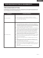
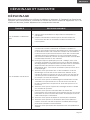
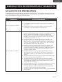
TROUBLE POSSIBLE REMEDY
Fan will not start
A. Check all fuses or circuit breakers. Replace if missing.
B. Turn off electrical power and check all wire connections to
fan and in switch housing.
Fan sounds noisy
A. Use of standard light rheostat or continuously variable fan
speed wall control will always cause harmonic distortions, or
a humming noise. Many fan motors do not work quietly with
solid state variable controls. If a quiet wall control in desired,
use only 3-speed UL approved wall controls.
B. Always allow a few days “break in” time for any new fan at
medium or high speed. Try to diagnose the exact location of
the noise by listening carefully from several sides (Besides,
Motor, Light kit, etc.). Fan noise can come from a light kit.
C. Make sure all screws in the fan assembly and light kit are
tight and properly threaded. If not, back out and retighten.
Tighten the screws at least once a year because they may
loosen slowly over time and cause a clicking noise.
D. Make sure the light kit is securely fastened to the fan, and all
glass screws are nger tightened only. Do not tighten with
pliers or a screw driver.
E. Make sure mounting bracket is installed snugly to junction
box.
F. Make sure wire nuts in switch housing or canopy are not
tatting against each other or against wall of housing. Wrap
with electrical tape if necessary.
G. Make sure the canopy is not touching the ceiling.
H. Assure that the screws fastening blade holders to motor are
tight and the lock washers provided for that purpose have
been used.
I. Make sure all light bulbs are fully screwed in.
TROUBLESHOOTING
Troubleshoot your problem by using the chart below. If the appliance still does not
work properly, contact W Appliance Co. customer service center. Customers must
never troubleshoot internal components.

Page 18
ENGLISH
TROUBLESHOOTING & WARRANTY
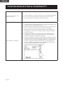
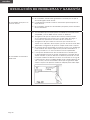
Fan turns but does not
move much air
A. The fan may be running in reverse, so air is directed upward.
B. The room may contain items that obstruct the air ow.
C. The fan may be too small for size of the room.
Fan shakes or wobbles
A. A small amount of movement is considered acceptable and
should not be considered a defect.
B. Make sure mounting bracket is tight at junction box/ceiling
with no movement at all, tighten screws if necessary.
C. Make sure all screws holding the blades to the blade arm
and blade arm to motor are tight. Make sure light kit/glass
screws are tight.
D. Some fan movement is normal. However, interchanging
an adjacent (side-by-side) blade pair may redistribute the
weight and result in smoother operation.
E. Most fan wobble problems are caused when blade levels are
unequal. Check this level by selecting a point on the ceiling
above the tip of one of the blades. Measure this distance as
shown in Figure 10. Measurements bias should always be
within ⅛”. Rotate the fan until the next blade is positioned
for measurement. Repeat for each blade.

Page 19
ENGLISH
TROUBLESHOOTING & WARRANTY
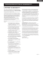
LIMITED WARRANTY
Any repair, replacement, or warranty service,
and all questions about this product should be
directed to W Appliance Co. at 844-299-0879
from the USA or Puerto Rico.
W Appliance Co. warrants to the original purchaser
that the product will be free from defects in material,
parts and workmanship for the period designated for
this product. The warranty commences the day the
product is purchased and covers up to a period of
1 year (12 months) for labor/1 year (12 months) for
parts (manufacturing defects only).
W Appliance Co. agrees that it will, at its option,
replace the defective product with either a new
or remanufactured unit equivalent to your original
purchase during the warranty period.
Exclusions: This warranty does not apply to the
below:
1. If the appearance or exterior of
the product has been damaged
or defaced, altered or modied in
design or construction.
2. If the product original serial number
has been altered or removed or
cannot be readily determined.
3. If there is damaged due to power
line surge, user damage to the
AC power cord or connection to
improper voltage source.
4. If damage is due to general misuse,
accidents or acts of God.
5. If repair attempts are done by
unauthorized service agents, use of
parts other than genuine parts or
parts obtained from persons other
than authorized service companies.
6. On units that have been transferred
from the original owner.
7. On products that have been
purchased as refurbished, like new,
second-hand, in a “As-Is” or “Final
Sale” terms.
8. To products used in a commercial
or rental setting.
9. To products used in settings other
than ordinary household use or
used other than in accordance with
the provided instructions.
10. To damages for service calls for
improper installations.
11. Transportation and shipping costs
associated with the replacement of
the unit.
12. Service calls to instruct you how to
use your product.
13. Service calls to repair or replace
the house fuse, reset the circuit
breaker or correct the wiring in
the house.
REPAIR OR REPLACEMENT AS PROVIDED UNDER
THIS WARRANTY IS THE EXCLUSIVE REMEDY OF
THE CUSTOMER; W Appliance Co. SHALL NOT BE
LIABLE FOR ANY INCIDENTAL OR CONSEQUENTIAL
DAMAGES FOR BREACH OF ANY EXPRESS OR
IMPLIED WARRANTY ON THIS PRODUCT, EXCEPT
TO THE EXTENT PROHIBITED BY APPLICABLE LAW.
ANY IMPLIED WARRANTY OF MERCHANTABILITY
OF FITNESS FOR A PARTICULAR PURPOSE ON THIS
PRODUCT IS LIMITED TO THE DURATION OF THE
WARRANTY.
Some states do not allow the exclusion or limitations
of incidental or consequential damages, or limitations
on how long the warranty lasts. In these cases the
above exclusions or limitations may not apply to you.
This warranty gives you specic legal rights and you
may also have other rights which vary from state to
state.
Obtaining Service: To obtain service, product
literature, supplies or accessories please call
844-299-0879 to create a ticket for exchange/repair.
Please make sure to provide the date of purchase,
model number and a brief description of the problem.
Our customer service representative will contact you
or send detailed return instructions.
W Appliance Co. does not warrant that the appliance will work
properly in all environmental conditions, and makes no warranty
and representation, either implied or expressed, with respect
to the quality, performance, merchantability, or tness for a
particular purpose other than the purpose identied within this
user’s manual. W Appliance Co. has made every effort to ensure
that this user’s manual is accurate and disclaims liability for any
inaccuracies or omissions that may have occurred. Information
in this user’s manual is subject to change without notice and
does not represent a commitment on the part of W Appliance
Co.. W Appliance Co. reserves the right to make improvements
to this user’s manual and/or to the products described in this
user’s manual at any time without notice. If you nd information
in this manual that is incorrect, misleading, or incomplete, please
contact us at 844-299-0879.
W Appliance Co.
1356 Broadway
New York, NY 10018

© 2021 Commercial Cool is a W Appliance Company. All Rights Reserved.
La page est en cours de chargement...
La page est en cours de chargement...
La page est en cours de chargement...
La page est en cours de chargement...
La page est en cours de chargement...
La page est en cours de chargement...
La page est en cours de chargement...
La page est en cours de chargement...
La page est en cours de chargement...
La page est en cours de chargement...
La page est en cours de chargement...
La page est en cours de chargement...
La page est en cours de chargement...
La page est en cours de chargement...
La page est en cours de chargement...
La page est en cours de chargement...
La page est en cours de chargement...
La page est en cours de chargement...
La page est en cours de chargement...
La page est en cours de chargement...
La page est en cours de chargement...
La page est en cours de chargement...
La page est en cours de chargement...
La page est en cours de chargement...
La page est en cours de chargement...
La page est en cours de chargement...
La page est en cours de chargement...
La page est en cours de chargement...
La page est en cours de chargement...
La page est en cours de chargement...
La page est en cours de chargement...
La page est en cours de chargement...
La page est en cours de chargement...
La page est en cours de chargement...
La page est en cours de chargement...
La page est en cours de chargement...
La page est en cours de chargement...
La page est en cours de chargement...
La page est en cours de chargement...
La page est en cours de chargement...
-
 1
1
-
 2
2
-
 3
3
-
 4
4
-
 5
5
-
 6
6
-
 7
7
-
 8
8
-
 9
9
-
 10
10
-
 11
11
-
 12
12
-
 13
13
-
 14
14
-
 15
15
-
 16
16
-
 17
17
-
 18
18
-
 19
19
-
 20
20
-
 21
21
-
 22
22
-
 23
23
-
 24
24
-
 25
25
-
 26
26
-
 27
27
-
 28
28
-
 29
29
-
 30
30
-
 31
31
-
 32
32
-
 33
33
-
 34
34
-
 35
35
-
 36
36
-
 37
37
-
 38
38
-
 39
39
-
 40
40
-
 41
41
-
 42
42
-
 43
43
-
 44
44
-
 45
45
-
 46
46
-
 47
47
-
 48
48
-
 49
49
-
 50
50
-
 51
51
-
 52
52
-
 53
53
-
 54
54
-
 55
55
-
 56
56
-
 57
57
-
 58
58
-
 59
59
-
 60
60


commercial cool CCF45P20 Manuel utilisateur
- Catégorie
- Ventilateurs ménagers
- Taper
- Manuel utilisateur
dans d''autres langues
Autres documents
-
for Living Nordica 36 Le manuel du propriétaire
-
Canarm CF-24C Manuel utilisateur
-
Canarm CF48C153MBK Manuel utilisateur
-
Hinkley 903880FGT-NDD Manuel utilisateur
-
Lowe s C-ST52BNK5D1 Manuel utilisateur
-
 Hinkley 903752 52 Inch Chisel Ceiling Fan Manuel utilisateur
-
 Hinkley 903760 60 Inch Chisel Ceiling Fan Manuel utilisateur
-
Hinkley 903680FMB-LDD Manuel utilisateur
-
Hinkley 60 Inch Chisel Indoor and Outdoor Ceiling Fan Manuel utilisateur

