
LIBRETTO DI ISTRUZIONI
DEI PROGRAMMATORI ELETTRONICI UNIVERSALI MONOFASE 230V 50/60Hz
PER APRICANCELLI SCORREVOLI CON FINECORSA pag. 3, 4, 5
1
ON
OFF
DIP-SWITCH B
1
ON
OFF
DIP-SWITCH B
1
ON
OFF
DIP-SWITCH B
LIBRETTO DI ISTRUZIONI
DEI PROGRAMMATORI ELETTRONICI UNIVERSALI MONOFASE 230V 50/60Hz
PER APRICANCELLI A BATTENTE OLEODINAMICI ED ELETTROMECCANICI
A 1 O 2 ANTE pag. 6, 7, 8
GB
LIBRETTO DI ISTRUZIONI
DEI PROGRAMMATORI ELETTRONICI UNIVERSALI MONOFASE 230V 50/60Hz
PER APRIBASCULANTI OLEODINAMICI ED ELETTROMECCANICI pag. 9, 10, 11
XE
X
Dis. N. 6739
dotato di regolazione elettrica della coppia, adatto ad attuatori elettromeccanici
privi di frizione meccanica
non dotato di regolazione elettrica della coppia (per attuatori dotati di frizione
meccanica e registri della forza idraulica)
GB
INSTRUCTIONS
SINGLE-PHASE UNIVERSAL ELECTRONIC CONTROL BOXES - 230V 50/60Hz
FOR SLIDING GATE OPERATORS FITTED WITH LIMIT SWITCHES pages 13, 14, 15
INSTRUCTIONS
SINGLE-PHASE UNIVERSAL ELECTRONIC CONTROL BOXES - 230V 50/60Hz
FOR SINGLE OR DOUBLE OIL-HYDRAULIC & ELECTRO-MECHANICAL SWINGING GATES
pages 16, 17, 18
INSTRUCTIONS
SINGLE-PHASE UNIVERSAL ELECTRONIC CONTROL BOXES - 230V 50/60Hz
FOR OIL-HYDRAULIC & ELECTRO-MECHANICAL GARAGE DOOR OPERATORS
pages.19, 20, 21
not equipped with electric torque control (designed for operators fitted with
mechanical clutch and pressure valve adjustment)
equipped with electric torque control, designed for electro-mechanical operators
without mechanical clutch
NOTICES D'INSTRUCTIONS
PROGRAMMATEURS ELECTRONIQUES UNIVERSELS 230V 50/60Hz MONOPHASE
POUR OUVRE-PORTAILS COULISSANTS AVEC FINS DE COURSE pages 23, 24, 25
NOTICES D'INSTRUCTIONS
PROGRAMMATEURS ELECTRONIQUES UNIVERSELS 230V 50/60Hz MONOPHASE
POUR OUVRE-PORTAILS A BATTANT HYDRAULIQUES ET ELECTROMECANIQUES
AVEC 1 OU 2 VANTAUX pages 26, 27, 28
NOTICES D'INSTRUCTIONS
PROGRAMMATEURS ELECTRONIQUES UNIVERSELS 230V 50/60Hz MONOPHASE
POUR OUVRE-PORTES BASCULANTS HYDRAULIQUES ET ELECTROMECANIQUES
pages 29, 30, 31
sans réglage électrique du couple (pour actuateurs avec friction mécanique et
registres de la force hydraulique)
avec réglage électrique du couple, pour actuateurs électromécaniques sans
friction mécanique
IT
FR
no dotado de regulación eléctrica de las coplas (para actuadores de fricción
mecánica y registros de la fuerza hidráulica)
ES
GB
IT
FR
ES dotado de rugulación electrica de las coplas, adapto para actuadores
electromecánicos falto de fricción mecánica
IT
FR
FOLLETO DE INSTRUCCIONES
DE LOS PROGRAMADORES ELECTRONICOS UNIVERSALES MONOPHASE 230V
50/60Hz PARA VERJAS CORREDERAS CON FINAL DE CARRERA pág. 33, 34, 35
ES
GB
IT
FR
ES FOLLETO DE INSTRUCCIONES
DE LOS PROGRAMADORES ELECTRONICOS UNIVERSALES MONOPHASE 230V 50/60Hz
PARA VERJAS BATIENTE HOLODINAMICOS Y ELECTROMECANICOS A 1 O 2 HOJAS
pág. 36, 37, 38
GB
IT
FR
ES FOLLETO DE INSTRUCCIONES
DE LOS PROGRAMADORES ELECTRONICOS UNIVERSALES MONOPHASE 230V
50/60Hz PARA VERJAS BASCULANTE HOLODINAMICOS Y ELECTROMECANICOS
pág. 39, 40, 41
Via Mantova, 177/A - 37053 Cerea (VR) Italy
Ph. +39 0442 330422 Fax +39 0442 331054
[email protected] - www.fadini.net

pag 2
IT
NEL CASO DI MANCATO FUNZIONAMENTO
- Accertarsi che l'alimentazione al programmatore elettronico sia 230V ±10%
- Accertarsi che l'alimentazione al Motore Elettrico sia 230V ±10%
- Controllare tutti i fusibili
- Controllare che le Fotocellule siano in contatto chiuso
- Controllare che non ci sia una caduta di tensione tra il Programmatore Elpro e Motore Elettrico
- Regolare il Selettore della forza motore in funzione del peso e dell'anta
- Controllare tutti i contatti NC del programmatore
IMPORTANTE PER L'INSTALLAZIONE E IL CORRETTO FUNZIONAMENTO:
- Il Programmatore deve essere installato in un luogo asciutto e protetto, sono previsti a proposito i fori di fissaggio sul contenitore universale FADINI
e su cassetta commerciale
- Accertarsi che l'alimentazione al programmatore elettronico sia 230V ±10%
- Accertarsi che l'alimentazione al Motore Elettrico sia 230V ±10%
- Per distanze superiori ai 50 metri aumentare la sezione dei fili.
- Applicare un interruttore Magneto-Termico Differenziale del tipo 0,03A ad alta sensibilità all'alimentazione del programmatore
- Alimentazione, Motore Elettrico, Lampeggiante usare fili di sezione da 1,5mm² fino a 50m di distanza
- Finecorsa, Fotocellule, Pulsantiere e accessori usare cavi con fili da 1mm²
- Se non si usano le Fotocellule eseguire un ponte tra i morsetti 1 e 2 e i tutti gli ingressi con contatti NC
- Se non si usa nessuna Pulsantiera eseguire un ponte tra i morsetti 3 e 6
- Trimmer del Tempo di Lavoro Apre/Chiude deve essere sempre superiore al tempo effettivo della corsa del cancello
N.B: Per applicazioni quali accensioni luci, Telecamere, ecc. utilizzare Relè Statici per non creare disturbi al microprocessore
174 18 21 23
10 11 12 13 14 15 16 19
17 20 22
2
262728
alimentazione
MOTORI ELETTRICI
MONOFASE 230V
85
39
M1 M2
6
L2
L1 L3 L4 L5 L6 L7 L8 L9
F3=2A
protezione
della bassa
tensione 24V
F1=5A
di rete
F2=5A
di rete
LAMPADA DI CORTESIA
230V MAX 100W
Si accende all'inizio del
movimento del
cancello e rimane
accesa per un tempo
fisso di 90 secondi
dopo la fine del ciclo
di lavoro
C1
Condensatore
Motore M1
C2
Condensatore
Motore M2
24 25
TRASFORMATORE
MICROPROCESSORE
VERSIONE 03
ON
OFF
123456789101112
DIP-SWITCH - A
MORSETTIERA PER
IL COLLEGAMENTO DEI LED
DELLA PULSANTIERA PULIN 3
1234567891011 1213 14 15 16 1718 19 20 21 22 23 24 25
28 2627
USCITA
24Vcc - 5W
TEMPO DI LAVORO
APRE-CHIUDE
scorrevole: 0-120s
battente/basculante: 0-60s
TEMPO DI PAUSA
0s - 220s
- RITARDO ANTA IN CHIUSURA: 0-10s
- APERTURA PEDONALE 0-30s
SELETTORE FORZA
MOTORE
SUPPORTO
PER SCHEDA
RADIO AD
INNESTO
-
+
2° coppia di
fotocellule oppure
contatto NC per
costa di sicurezza
NC
1° coppia di
fotocellule
contatto radio
finecorsa di chiusura
comune
apre
chiude
stop
finecorsa di apertura
comune
spia 24V max 3W
uscita 24Vac (carico max:
n°1 radio ricevente
n°2 coppie fotocellule)
alimentazione 12Vac
per elettroserratura
15VA max
USCITA 230Vac per
lampeggiante
max 25W e
Elettrocatenaccio
Alimentazione
scheda
230V - 50/60Hz ±10%
Uscita 24V /ca
per fotocellula TX
adibita al controllo DSA
Led di Diagnostica:
L1 Acceso = Presenza Tensione di rete 230V e integrità fusibili F1, F2, F3 (F4 solo per Elpro X)
L2 Acceso = 2° coppia Fotocellule o Costa di sicurezza, nessun ostacolo presente
L3 Acceso = 1° coppia di Fotocellule, nessun ostacolo presente
L4 Spento = Apre, si illumina ad impulso di comando apre
L5 Spento = Chiude, si illumina ad impulso del comando di chiusura
L6 Acceso = Blocco, si spegne ad impulso del comando di stop
L7 Spento = Radio, si illumina ad ogni impulso del trasmettitore e contatto radio
L8 = Finecorsa chiude, è spento a cancello chiuso. E' acceso durante il movimento e a cancello aperto sul finecorsa di apertura
L9 = Finecorsa apre, è spento a cancello aperto. E' acceso durante il movimento e a cancello chiuso sul finecorsa di chiusura
1234
ON
OFF
DIP-SWITCH - B
ATTENZIONE: prima di procedere ai collegamenti elettrici, selezionare la tipologia di automazione con il Dip
Switch B N°1 e leggere le istruzioni dedicate agli apricancelli installati:
SCORREVOLI da pag.3 a pag. 5 - BATTENTI da pag.6 a pag.8 - BASCULANTI da pag.9 a pag.11
!
NC
Simbologia
Contatto NC
Contatto NA
Led Acceso
Led Spento
Spia o lampada
Lampeggiatore
3029
29 30
+-
comune
comune
NEUTRO
FASE
-
+
-
+
XPROGRAMMATORI ELETTRONICI UNIVERSALI
MONOFASE 230V 50/60Hz
XE
solo per
ELPRO XE
!
Descrizione generale: I programmatori elettronici ELPRO X ed ELPRO XE sono stati realizzati come possibile soluzione per l'installatore che necessiti di un
sistema elettronico universale per qualsiasi tipologia di automazione si presenti. Adatti per apricancelli scorrevoli con finecorsa, sistemi a battente a 1 o
2 ante, provvisti di valvole di regolazione forza per ELPRO X, oppure automazioni elettromeccaniche per ELPRO XE, in quanto dispone di selettore di
regolazione forza motore, e apribasculanti con 1 o 2 motori con o senza finecorsa. Alimentato a 230V 50/60Hz monofase, l'ELPRO X e l'ELPRO XE rispondono
alle normative di sicurezza di Bassa Tensione 2006/95 CE e Compatibilità Elettromagnetica 2004/108/CE e 92/31 CEE, e pertanto si consiglia l'installazione
da parte di personale tecnico qualificato secondo le normative di sicurezza vigenti. La Ditta costruttrice non si assume responsabilità circa l'uso improprio
del programmatore; inoltre si riserva di apportare in qualunque momento modifiche e aggiornamenti al programmatore.
F4=630mA
di rete
solo per
ELPRO X
!

IT
pag 3
PER APRICANCELLI SCORREVOLI Dip-B N°1=ON
XE
Selettore a chiave:
Fotocellule:
1
DIP-SWITCH-A N° 1:
ON: ferma in apertura e inverte in chiusura
a ostacolo rimosso
OFF: non ferma in apertura e inverte in chiusura
in presenza di ostacolo
Contatto Radio (con
funzione
passo-passo):
collegando un qualsiasi contatto NA tra i
due morsetti si può ottenere ad ogni
impulso:
- Solo apertura: Dip 2=ON e Dip 5=OFF
- Inversione di marcia ad ogni impulso
Dip 2=OFF e Dip 5=OFF
- Passo Passo: Apre-Stop-Chiude-Stop
Dip 2=OFF e Dip 5=ON
- In fase di apertura non accetta nessun
comando. In pausa e in chiusura ad ogni
comando esegue lo stop con inversione di
marcia: Dip 2=ON e Dip 5=ON
ON: In apertura non inverte e non blocca
OFF: In apertura blocca e inverte sempre
2
ON: Passo passo con blocco intermedio
OFF: Inverte il movimento ad ogni impulso radio
5
DIP-SWITCH-A N°2 e N°5:
tutti i contatti NC degli
accessori di sicurezza
quali Fotocellule
(ricevitori) devono essere
collegati in serie ai
morsetti 1 e 2
Accessorio Collegamenti elettrici
contatti NA e NC da collegare ai
rispettivi morsetti dei selettori o
pulsantiere.
Tutte le possibili configurazioni sono
allegate ai rispettivi accessori di
comando
NC
NC
12
3456
NC
APRE
CHIUDE
STOP
COMUNE
CONTATTO
RADIO
COMUNE
3 7
L3 Acceso= nessun ostacolo presente, si
spegne ad ostacolo presente
L4 Spento= nessun contatto APRE, si
accende ad ogni impulso di apertura
L5 Spento= nessun contatto CHIUDE, si
accende ad ogni impulso di chiusura
L6 Acceso= contatto di STOP chiuso, si
spegne ad ogni impulso di stop
L7 Spento= nessun contatto RADIO, si
accende ad ogni impulso del contatto radio
Dip-Switch A
1 = ON Fotocellula ferma in apertura
2 = ON Radio non inverte in apertura
3 = ON Chiude in automatico
4 = ON Prelampeggio Attivo
5 = ON Radio passo-passo
6 = ON Servizio pedonale
ON
OFF
123456789101112
DIP-SWITCH - A
PER APRICANCELLI SCORREVOLI CON FINECORSA:
posizionare il Dip Switch B N°1= ON
7 = ON Nessuna funzione
8 = vedi collegamenti della COSTA di SICUREZZA
9 = vedi collegamenti della COSTA di SICUREZZA
10 = ON Lampeggiatore spento in pausa
11 = ON Richiude in Apertura e in pausa dopo passaggio su Fotocellule
12 = libero
Dip-Switch B
1 = ON modalita' APRICANCELLO SCORREVOLE
2 = ON Uomo presente
3 = libero
4 = ON controllo DSA fotocellule trasmettitori se collegati ai morsetti dedicati
Costa di sicurezza: 12
Contatto NC per costa di sicurezza. Permette l'inversione di
marcia per un breve tratto della corsa arrestando il cancello:
con Dip A n°9= ON, in entrambi i sensi di marcia
NOTA: se non presente la costa non è necessario ponticellare
l'ingresso del contatto, lasciando solo il Dip-A N°9=OFF
DIP-SWITCH-A N°8 E N°9:
ON: Aumento del tempo durante l'inversione
OFF: Nessun aumento del tempo di inversione
8
ON: Inversione di marcia con la costa
OFF: Nessuna inversione di marcia.
9
Finecorsa:
finecorsa di
chiusura
finecorsa di
apertura
comune
8910 IMPORTANTE: se i finecorsa non
sono utilizzati, ponticellare gli
ingressi 8 - 9 - 10
L8 Acceso= spento a cancello chiuso
L9 Acceso= spento a cancello aperto
1234
ON
OFF
DIP-SWITCH - B
L2 Acceso= nessun ostacolo presente, si
spegne ad ostacolo presente
234
1
ON
OFF
DIP-SWITCH - B
Dip-Switch e segnalazione LED delle varie funzioni
COLLEGAMENTI ELETTRICI AI MORSETTI PER L'APERTURA SCORREVOLE - Dip Switch B n°1=ON
12 13
uscita 24Vac carico max:
n°1 radio ricevente
n°2 coppie fotocellule
XPROGRAMMATORI ELETTRONICI UNIVERSALI
MONOFASE 230V 50/60Hz
XE
X

IT
pag 4
XE
Uscita 24V:
USCITA 24Vac per carico max:
n°2 coppie di fotocellule
n°1 Radio ricevente
n°1 Led selettore ZERO.EK / ZERO.K
Tutte le istruzioni sono allegate ai rispettivi
accessori di comando
Uscita per una eventuale lampada di segnalazione
24V max 3W dello stato dell'automazione:
Spia Accesa = Cancello Aperto
Spia Spenta = Cancello Chiuso
Lampeggia 0,5s (veloce) = movimento di chiusura
Lampeggia 1s (normale) = movimento di apertura
Uscita Spia di
Segnalazione da
24V - max 3W:
COMUNE
311
Alimentazione
Motore monofase
230V e condensatori:
COLLEGAMENTI ELETTRICI AI MORSETTI PER L'APERTURA SCORREVOLE - Dip Switch B n°1=ON
Accessorio Collegamenti elettrici Dip-Switch e segnalazione LED delle varie funzioni
N°1 MOTORE FINO A 0,5CV (0,36KW) MONOFASE 230V:
colllegare le alimentazioni ad una delle due uscite M1 o M2
USCITA 230Vac per
lampeggiante
max 25W
18
16 17
M1
COMUNE
16 1718
C1
Condensatore
Motore M1
N°1 MOTORE DA 1,0CV (0,72KW) MONOFASE 230V:
collegare in parallelo le uscite dei morsetti 16-19 , 17-21 e
18-20.
IMPORTANTE: con motore da 1,0CV sostituire i fusibili F1 e
F2 con fusibili da 6,3A
Collegare il
condensatore
Motore 1 ai
morsetti dedicati
0,5CV - 230V
C1
Condensatore
Motore M1
Lampeggiante 230V: 2322 DIP-SWITCH-A N°4 e N°10
ON: Prelampeggio prima dell'apertura
OFF: Senza prelampeggio
4
ON: Lampeggiante disattivato durante la pausa
in Funzionamento Automatico (con Dip 3= ON)
OFF: Lampeggia durante la pausa in
Funzionamento Automatico (con Dip 3= ON)
10
Alimentazione
scheda 230V: 24
NEUTRO
25
FASE
24 25
Alimentazione programmatore
230V - 50/60Hz ±10%
TEMPO DI PAUSA
0s - 220s
TEMPO DI LAVORO
APRE-CHIUDE
0s - 120s
12 13
18 21
16 19
17 20
M1
COMUNE
16 1718 19 20 21
1,0CV - 230V
Collegamento
Pulin 3: morsettiera per
il collegamento dei led
della pulsantiera
Pulin 3
262728
28 2627
USCITA
24Vcc - 5W max
3
Uscita 24Vcc-5W:
REGOLAZIONE DELLA FORZA:
La regolazione della Forza attraverso il
Selettore deve essere necessaria a muovere
il cancello. Una forza troppo elevata del
cancello comporta una non corretta
installazione secondo normative di
sicurezza EN 12445 e EN 12453 ed un
pericolo!
PER APRICANCELLI SCORREVOLI Dip-B N°1=ON
Collegare il
condensatore
Motore 1 ai
morsetti dedicati
3029
29 30
+-
-
+
-
+
XPROGRAMMATORI ELETTRONICI UNIVERSALI
MONOFASE 230V 50/60Hz
XE
solo per ELPRO XE
!
X
Astro 43

IT
pag 5
XE
AUTOMATICO / SEMIAUTOMATICO:
Ciclo Automatico: ad un impulso di comando apre, il cancello si apre, si ferma in Pausa per
il tempo impostato sul Trimmer Pausa, scaduto il quale richiude automaticamente
Ciclo Semiautomatico: ad un impulso di comando apre il cancello si apre e si blocca in
posizione aperto. Per Chiudere il passaggio bisogna dare limpulso di chiusura.
Dip - Switch e segnalazione LED delle varie funzioni
Trimmer Pausa: si regola il tempo di
pausa nella modalità Automatico
da 1s fino 220s
3
ON: Chiude in Automatico
OFF: Semiautomatico
DIP-SWITCH-A N°3:
Descrizione
11
ON: Richiusura automatica al passaggio sulle
fotocellule dopo 3 secondi
OFF: Nessuna richiusura automatica
DIP-SWITCH-A N°11:
Trimmer Pedonale: si regola la distanza
di apertura del cancello per il contatto
di apertura pedonale fino a 30s
APERTURA PEDONALE:
Si ottiene l'apertura pedonale da cancello chiuso tramite il
comando Apre e Dip-A N°6=ON: un primo comando di apertura
apre l'anta per un tempo impostato dal trimmer.
Un secondo impulso lo apre completamente.
(Si consiglia l'uso dell'apertura pedonale con Dip-A N°3=ON per
la richiusura automatica).
La funzione "Apertura pedonale" non è attiva durante il primo
ciclo di funzionamento, successivo ad una mancanza di
tensione di alimentazione.
6
ON: Apertura pedonale
OFF: Esclusione dell'apertura pedonale
DIP-SWITCH-A N°6:
4
ON: Attiva il controllo delle sicurezze DSA
OFF: Disattiva controllo delle sicurezze DSA
DIP-SWITCH-B N°4:
UOMO PRESENTE:
Si ottiene il comando di apertura e chiusura "ad azione mantenuta" (senza autotenuta nei
Relè), quindi l'attiva presenza dell'operatore durante tutto il movimento dell'automazione
fino al rilascio del pulsante o della chiave del selettore 2
ON: Attiva funzione Uomo Presente
OFF: Disattiva Uomo Presente
DIP-SWITCH-B N°2:
COMUNE
NA
Orologio esterno
3
ON: Chiude in Automatico
DIP-SWITCH-A N°3:
34
APRE
COMUNE
Uscita 24V ca
per fotocellula TX
adibita al controllo DSA
1615
FUNZIONI PER L'APERTURA SCORREVOLE - Dip Switch B n°1=ON
PER APRICANCELLI SCORREVOLI Dip-B N°1=ON
IMPORTANTE: utilizzare sempre e solo con
Dip-A N°3= ON
APERTURA MEDIANTE OROLOGIO ESTERNO:
Collegamento: collegare in parallelo il contatto NA
dell'Orologio con il morsetto n°4 APRE e n°3 COMUNE,
attivando la richiusura automatica con il Dip-Switch
n°3=ON
Funzionamento: programmare l'orario di apertura
sull'orologio, all'ora impostata il cancello si apre
rimanendo aperto (il lampeggiante si spegne), e non
accetterà più nessun comando (anche radio) sino allo
scadere del tempo impostato sull'orologio, allo scadere
del quale, dopo il tempo di pausa, seguirà la chiusura
automatica.
Durante la sosta a cancello aperto con comando
"orologio" la spia di segnalazione emette due lampeggi
ravvicinati seguiti da una lunga pausa
-
+
-
+
XPROGRAMMATORI ELETTRONICI UNIVERSALI
MONOFASE 230V 50/60Hz
XE
DSA: CONTROLLO AUTOMATICO DELLE FOTOCELLULE
Per il controllo DSA (Dispositivo Sicurezza Autotest) bisogna collegare a
questa uscita le sole fotocellule trasmettitori e selezionare il Dip-B
N°4=ON: prima di ogni movimento del cancello, se questa funzione è
abilitata, l'Elpro X e l'Elpro XE controllano che tutti i dispositivi fotocellule
collegati siano liberi da ostacoli presenti, e correttamente funzionanti,
in caso contrario il cancello non parte
X
RICHIUSURA AL PASSAGGIO SULLE FOTOCELLULE: in fase di apertura e in pausa (con DIP-A
N°3=ON)
Funzione che permette la richiusura automatica del cancello dopo 3s dal passaggio
attraverso il fascio sulle fotocellule.

IT
pag 6
XE
Selettore a chiave:
1° coppia di
Fotocellule: installate
esternamente
1
DIP-SWITCH-A N° 1:
ON: ferma in apertura e inverte in chiusura
a ostacolo rimosso
OFF: non ferma in apertura e inverte in chiusura
in presenza di ostacolo
ON: In apertura non inverte e non blocca
OFF: In apertura blocca e inverte sempre
2
ON: Passo passo con blocco intermedio
OFF: Inverte il movimento ad ogni impulso radio
5
DIP-SWITCH-A N°2 e N°5 :
Accessorio Collegamenti elettrici Dip-Switch e segnalazione LED delle varie funzioni
contatti NA e NC da collegare ai
rispettivi morsetti dei selettori o
pulsantiere.
Tutte le possibili configurazioni sono
allegate ai rispettivi accessori di
comando
NC
NC
12
3456
NC
APRE
CHIUDE
STOP
COMUNE
CONTATTO
RADIO
COMUNE
3 7
L3 Acceso= nessun ostacolo presente, si
spegne ad ostacolo presente
L4 Spento= nessun contatto APRE, si
accende ad ogni impulso di apertura
L5 Spento= nessun contatto CHIUDE, si
accende ad ogni impulso di chiusura
L6 Acceso= contatto di STOP chiuso, si
spegne ad ogni contatto di stop
L7 Spento= nessun contatto RADIO, si
accende ad ogni impulso del contatto radio
Dip-Switch A
1 = ON Fotocellula ferma in apertura
2 = ON Radio non inverte in apertura
3 = ON Chiude in automatico
4 = ON Prelampeggio Attivo
5 = ON Radio passo-passo
6 = ON Servizio pedonale
ON
OFF
123456789101112
DIP-SWITCH - A
PER APRICANCELLI BATTENTI:
posizionare il Dip Switch B N°1= OFF
234
1
ON
OFF
DIP-SWITCH - B
7 = ON Colpo d'ariete in apetura
8 = ON Elimina ritardo anta in apertura, i motori partono assieme
9 = ON Abilita ingresso 2° coppia di fotocellule
10 = ON Lampeggiatore spento in pausa
11 = ON Richiude in Apertura e in pausa dopo passaggio su Fotocellule
12 = ON Memoria tempi Attiva per installazioni ad alta frequenza dilavoro
Dip-Switch B
1 = OFF modalita' APRICANCELLO BATTENTE
2 = ON Uomo presente
3 = ON inversione di marcia con dispositivi di protezione dell'area di apertura
4 = ON controllo DSA fotocellule trasmettitori se collegati ai morsetti dedicati
2° coppia di
Fotocellule: installate
internamente
12 DIP-SWITCH-A N°9:
ON: Abilita la 2° coppia fotocellule
OFF: 2° coppia fotocellule non utilizzata
9
1234
ON
OFF
DIP-SWITCH - B
L2 Acceso= nessun ostacolo presente, si
spegne ad ostacolo presente
Contatto Radio (con
funzione
passo-passo):
uscita 24Vac carico max:
n°1 radio ricevente
n°2 coppia fotocellule
Finecorsa: se non
presenti ponticellare i
morsetti oppure utilizzare
l'ingresso 9 e 10 per
dispositivo di inversione
di marcia in apertura
(descritto a pag.8) (*)
IMPORTANTE: se i finecorsa non sono
utilizzati, ponticellare gli ingressi 8 e 10
con il comune 9.
I morsetti 9 e 10 sono ingressi anche
per il contatto NC in apertura: il loro
intervento in fase di apertura inverte la
marcia per un breve tratto (vedere
paragrafo funzioni pag.8)
L8 Acceso= spento a cancello chiuso
L9 Acceso= spento a cancello aperto
finecorsa di
chiusura
finecorsa di
apertura
comune
8910
COLLEGAMENTI ELETTRICI AI MORSETTI PER L'APERTURA A BATTENTE - Dip Switch B n°1=OFF
PER APRICANCELLI A BATTENTE Dip-B N°1=OFF
12 13
12 13
uscita 24Vac carico max:
n°1 radio ricevente
n°2 coppia fotocellule
tutti i contatti NC degli
accessori di sicurezza
quali Fotocellule
(ricevitori) devono essere
collegati in serie ai
morsetti 1 e 2
collegando un qualsiasi contatto NA tra i
due morsetti si può ottenere ad ogni
impulso:
- Solo apertura: Dip 2=ON e Dip 5=OFF
- Inversione di marcia ad ogni impulso
Dip 2=OFF e Dip 5=OFF
- Passo Passo: Apre-Stop-Chiude-Stop
Dip 2=OFF e Dip 5=ON
- In fase di apertura non accetta nessun
comando. In pausa e in chiusura ad ogni
comando esegue lo stop con inversione di
marcia: Dip 2=ON e Dip 5=ON
X
XPROGRAMMATORI ELETTRONICI UNIVERSALI
MONOFASE 230V 50/60Hz
XE
Con Dip A n°9= ON e collegato l'ingresso NC: il cancello
rimane fermo in posizione bloccato per tutto il tempo che le
fotocellule sono impegnate.
- in fase di apertura: a ostacolo rimosso riprende l'apertura
- in fase di chiusura: a ostacolo rimosso inverte il movimento
NOTA: se non presente non è necessario ponticellare
l'ingresso del contatto, lasciando solo il Dip-A N°9=OFF
NC

IT
pag 7
Uscita 24V:
USCITA 24Vac per carico max:
n°2 coppie di fotocellule
n°1 Radio ricevente
n°1 Led selettore Chis 37 / Chis E37
Tutte le istruzioni sono allegate ai rispettivi
accessori di comando
Uscita Spia di
Segnalazione da
24V- max 3W:
COMUNE
311
Alimentazione
Motore monofase
230V e condensatori:
COLLEGAMENTI ELETTRICI AI MORSETTI PER L'APERTURA A BATTENTE - Dip Switch B n°1=OFF
Accessorio Collegamenti elettrici Dip - Switch e segnalazione LED delle varie funzioni
USCITA 230Vac per
lampeggiante
max 25W
Se presente un solo motore:
1) Collegare l'alimentazione ai morsetti del motore M1
2) Escludere il ritardo anta in apertura Dip-A N°8=ON
3) Azzerare il Trimmer di Ritardo Anta in chiusura al minimo
motore
ritardato in
chiusura
Elettrocatenaccio e
Lampeggiante 230V: 2322 DIP-SWITCH-A N°4 e N°10
ON: Prelampeggio prima dell'apertura
OFF: senza prelampeggio
4
ON: Disattivato durante la pausa in
Funzionamento Automatico (con Dip 3= ON)
OFF: Alimentazione presente durante la pausa in
Funzionamento Automatico (con Dip 3= ON)
10
Alimentazione
scheda 230V: 24
NEUTRO
25
FASE
24 25
Alimentazione programmatore
230V - 50/60Hz ±10%
TEMPO DI PAUSA
0s - 220s
TEMPO DI LAVORO
APRE-CHIUDE
0s - 60s
12 13
Uscita per una eventuale lampada di segnalazione
24V max 3W dello stato dell'automazione:
Spia Accesa = Cancello Aperto
Spia Spenta = Cancello Chiuso
Lampeggia 0,5s (veloce)= movimento di chiusura
Lampeggia 1s (normale)= movimento di apertura
Elettroserratura: 14 15 Uscita alimentazione 12Vac
per elettroserratura 15VA max
L'elettroserratura va installata
sull'anta del motore M1
ritardato in chiusura
motore
ritardato in
apertura
18 21
16 19
17 20
M1
COMUNE
16 1718 19 20 21
M2
COMUNE
RITARDO ANTA IN
CHIUSURA: 0s - 10s
Se presenti N°2 motori:
Il ritardo anta in apertura fisso a 2s se necessita deve
essere attivo con Dip-A N°8=OFF
DIP-SWITCH-A N°8
ON: Elimina il ritardo anta in apertura
OFF: E' attivo un ritardo anta di 2s in apertura
8
USCITA 230Vac per
Elettrocatenaccio: è
importante sempre togliere
alimentazione durante la
pausa con Dip-A n°10=ON
Alimentazione
led Pulin 3: 262728
28 2627
3
USCITA
24Vcc - 5W max
Uscita 24Vcc-5W:
morsettiera per
il collegamento dei led
della pulsantiera
Pulin 3
XE PER APRICANCELLI A BATTENTE Dip-B N°1=OFF
3029
29 30
+-
REGOLAZIONE DELLA FORZA:
La regolazione della Forza attraverso il
Selettore deve essere necessaria a muovere
il cancello. Una forza troppo elevata del
cancello comporta una non corretta
installazione secondo normative di sicurezza
EN 12445 e EN 12453 ed un pericolo!
C1
Condensatore
Motore M1
C2
Condensatore
Motore M2
-
+
-
+
-
+
XPROGRAMMATORI ELETTRONICI UNIVERSALI
MONOFASE 230V 50/60Hz
XE
X
solo per ELPRO XE
!
Astro 43

IT
pag 8
XE
APERTURA MEDIANTE OROLOGIO ESTERNO:
Collegamento: collegare in parallelo il contatto NA dell'Orologio
con il morsetto n°4 APRE e n°3 COMUNE, attivando la richiusura
automatica con il Dip-Switch n°3=ON
Funzionamento: programmare l'orario di apertura sull'orologio,
all'ora impostata il cancello si apre rimanendo aperto (il
lampeggiante si spegne), e non accetterà più nessun comando
(anche radio) sino allo scadere del tempo impostato sull'orologio,
allo scadere del quale, dopo il tempo di pausa, seguirà la
chiusura automatica.
Dip - Switch e segnalazione LED delle varie funzioni
Trimmer Pausa: si regola il tempo di
pausa nella modalità Automatico
da 1s fino 220s
3
ON: Chiude in Automatico
OFF: Semiautomatico
DIP-SWITCH-A N°3:
Descrizione
RICHIUSURA AL PASSAGGIO SULLE FOTOCELLULE: in fase di apertura e in pausa
(con DIP-A N°3=ON)
Funzione che permette la richiusura automatica del cancello dopo 3s dal passaggio
attraverso il fascio sulle fotocellule. Se presente anche la 2° coppia di fotocellule, bisogna
abilitarle con Dip-A N°9=ON.
DIP-SWITCH-A N°9 E N°11:
APERTURA PEDONALE PER IL SOLO MOTORE M1
Si ottiene l'apertura pedonale da cancello chiuso tramite il comando Apre: un primo
comando di apertura apre l'anta del motore M1. Con un secondo impulso di apertura
si apre completamente, assieme all'altra anta del motore M2.
La funzione "Apertura pedonale" non è attiva durante il primo ciclo di funzionamento,
successivo ad una mancanza di tensione di alimentazione. 6
ON: Apertura 1 anta pedonale M1
OFF: Esclusione dell'apertura pedonale
DIP-SWITCH-A N°6:
UOMO PRESENTE:
Si ottiene il comando di apertura e chiusura "ad azione mantenuta" (senza autotenuta nei
Relè), quindi l'attiva presenza dell'operatore durante tutto il movimento dell'automazione
fino al rilascio del pulsante o della chiave del selettore 2
ON: Attiva funzione Uomo Presente
OFF: Disattiva Uomo Presente
DIP-SWITCH-B N°2:
3
ON: Chiude in Automatico
DIP-SWITCH-A N°3:
COMUNE
NA
Orologio esterno
34
APRE
COMUNE
11
ON: Richiusura automatica al passaggio sulla
coppia fotocellule dopo 3 secondi
OFF: Nessuna richiusura automatica
ON: Abilita la 2° coppia fotocellule
OFF: 2° coppia fotocellule non utilizzata
9
Uscita 24V /ca
per fotocellula TX
adibita al controllo DSA
1615
COLPO D'ARIETE IN APERTURA:
Funzione che permette di facilitare il disimpegno dell'Elettroserratura a cancello
completamente chiuso, anche in modalita' Apertura Pedonale: le ante del cancello
chiuso, prima di aprire vengono spinte in chiusura per 2 secondi.
DIP-SWITCH-A N°7:
ON: Abilita il colpo d'ariete in apertura per 2s
OFF: Disabilita la funzione colpo d'ariete
7
UTILIZZO CONDOMINIALE:
Funzione per utilizzi altamente intensivi con frequenti inversioni di marcia: questa funzione
abilitata tiene conto del tempo rimanente di lavoro quando c'è una inversione di marcia
o un passaggio sulle fotocellule
DIP-SWITCH-A N°12:
12
ON:Memoria dei tempi di lavoro attiva
OFF: Funzionamento normale senza memoria
NC in
apertura
comune
8910
3
ON: Attiva l'inversione di marcia in apertura se
impegnati i dispositivi di sicurezza NC collegati
ai morsetti 9 e 10
OFF: Funzionamento normale con finecorsa
DIP-SWITCH-B N°3:
FUNZIONI PER L'APERTURA A BATTENTE - Dip Switch B n°1=OFF
PER APRICANCELLI A BATTENTE Dip-B N°1=OFF
4
ON: Attiva il controllo delle sicurezze DSA
OFF: Disattiva controllo delle sicurezze DSA
DIP-SWITCH-B N°4:
IMPORTANTE: utilizzare sempre e solo con
Dip-A N°3= ON
-
+
X
XPROGRAMMATORI ELETTRONICI UNIVERSALI
MONOFASE 230V 50/60Hz
XE
INVERSIONE DI MARCIA IN APERTURA:
IMPORTANTE: (*) se presenti i finecorsa sui morsetti 9 e 10,
questa funzione non può essere utilizzata (vedere pag.6)
Interviene solo durante la fase di apertura delle ante, quindi è
da utilizzare per la protezione delle zone poste tra le ante in
apertura ed eventuali ostacoli fissi (muri di recinzione o pilastri)
per evitare rischi di schiacciamento. Allo scadere del tempo di
pausa richiude (se attiva la funzione di chiusura automatica
Dip-A N°3=ON).
AUTOMATICO / SEMIAUTOMATICO:
Ciclo Automatico: ad un impulso di comando apre, il cancello si apre, si ferma in Pausa per
il tempo impostato sul Trimmer Pausa, scaduto il quale richiude automaticamente
Ciclo Semiautomatico: ad un impulso di comando apre il cancello si apre e si blocca in
posizione aperto. Per Chiudere il passaggio bisogna dare limpulso di chiusura.
DSA: CONTROLLO AUTOMATICO DELLE FOTOCELLULE
Per il controllo DSA (Dispositivo Sicurezza Autotest) bisogna collegare a
questa uscita le sole fotocellule trasmettitori e selezionare il Dip-B
N°4=ON: prima di ogni movimento del cancello, se questa funzione è
abilitata, l'Elpro X e l'Elpro XE controllano che tutti i dispositivi fotocellule
collegati siano liberi da ostacoli presenti, e correttamente funzionanti,
in caso contrario il cancello non parte

IT
pag 9
X
Dip-Switch A
1 = ON Fotocellula ferma in apertura
2 = ON Radio non inverte in apertura
3 = ON Chiude in automatico
4 = ON Prelampeggio Attivo
5 = ON Radio passo-passo
6 = libero
ON
OFF
123456789101112
DIP-SWITCH - A
PER APRICANCELLI BASCULANTI:
posizionare il Dip Switch B N°1= ON
234
1
ON
OFF
DIP-SWITCH - B
7 = libero
8 = vedi collegamenti della COSTA di SICUREZZA
9 = vedi collegamenti della COSTA di SICUREZZA
10 = ON Lampeggiatore spento in pausa
11 = ON Richiude in Apertura e in pausa dopo passaggio su Fotocellule
12 = ON Memoria tempi Attiva per installazioni ad alta frequenza dilavoro
Dip-Switch B
1 = ON modalita' APRICANCELLO BASCULANTE
2 = ON Uomo presente
3 = libero
4 = ON controllo DSA fotocellule trasmettitori se collegati ai morsetti dedicati
1234
ON
OFF
DIP-SWITCH - B
Selettore a chiave:
Fotocellule :
1
DIP-SWITCH-A N° 1:
ON: ferma in apertura e inverte in chiusura
a ostacolo rimosso
OFF: non ferma in apertura e inverte in chiusura
in presenza di ostacolo
ON: In apertura non inverte e non blocca
OFF: In apertura blocca e inverte sempre
2
ON: Passo passo con blocco intermedio
OFF: Inverte il movimento ad ogni impulso radio
5
DIP-SWITCH-A N°2 e N°5:
Accessorio Collegamenti elettrici Dip-Switch e segnalazione LED delle varie funzioni
contatti NA e NC da collegare ai
rispettivi morsetti dei selettori o
pulsantiere.
Tutte le possibili configurazioni sono
allegate ai rispettivi accessori di
comando
tutti i contatti NC degli
accessori di sicurezza
quali Fotocellule
(ricevitori) devono essere
collegati in serie ai
morsetti 1 e 2
3456
NC
APRE
CHIUDE
STOP
COMUNE
CONTATTO
RADIO
COMUNE
3 7
L3 Acceso= nessun ostacolo presente, si
spegne ad ostacolo presente
L4 Spento= nessun contatto APRE, si
accende ad ogni impulso di apertura
L5 Spento= nessun contatto CHIUDE, si
accende ad ogni impulso di chiusura
L6 Acceso= contatto di STOP chiuso, si
spegne ad ogni contatto di stop
L7 Spento= nessun contatto RADIO, si
accende ad ogni impulso del contatto radio
12 13
uscita 24Vac carico max:
n°1 radio ricevente
n°2 coppie fotocellule
Contatto Radio con
funzione
passo-passo:
Finecorsa: IMPORTANTE: se i finecorsa non sono
utilizzati, ponticellare gli ingressi 8 e 10
con il comune 9.
L8 Acceso= spento a cancello chiuso
L9 Acceso= spento a cancello aperto
finecorsa di
chiusura
finecorsa di
apertura
comune
8910
NC
NC
12
Costa di sicurezza: 12
Costa di sicurezza permette l'inversione di marcia per un
breve tratto della corsa arrestando il cancello: con DIp A
n°9= ON, in entrambi i sensi di marcia
NOTA: se non presente non è necessario ponticellare
l'ingresso del contatto, lasciando solo il DIp-A N°9=OFF
DIP-SWITCH-A N°8 E N°9:
ON: Aumento del tempo durante l'inversione
OFF: Nessun aumento del tempo di inversione
8
ON: Inversione di marcia con la costa
OFF: Nessuna inversione di marcia.
9
L2 Acceso= nessun ostacolo presente, si
spegne ad ostacolo presente
COLLEGAMENTI ELETTRICI AI MORSETTI PER L'APERTURA BASCULANTE - Dip Switch B n°1=ON
PER APRICANCELLI BASCULANTE Dip-B N°1=ON
collegando un qualsiasi contatto NA tra i
due morsetti si può ottenere ad ogni
impulso:
- Solo apertura: Dip 2=ON e Dip 5=OFF
- Inversione di marcia ad ogni impulso
Dip 2=OFF e Dip 5=OFF
- Passo Passo: Apre-Stop-Chiude-Stop
Dip 2=OFF e Dip 5=ON
- In fase di apertura non accetta nessun
comando. In pausa e in chiusura ad ogni
comando esegue lo stop con inversione
di marcia: Dip 2=ON e Dip 5=ON
XPROGRAMMATORI ELETTRONICI UNIVERSALI
MONOFASE 230V 50/60Hz
XE
NC
XE

IT
Uscita Spia di
Segnalazione da
24V- max 3W:
COMUNE
311 Uscita per una eventuale lampada di segnalazione
24V max 3W dello stato dell'automazione:
Spia Accesa = Cancello Aperto
Spia Spenta = Cancello Chiuso
Lampeggia 0,5s (veloce)= movimento di chiusura
Lampeggia 1s (normale)= movimento di apertura
XE
pag 10
Uscita 24V:
USCITA 24Vac per carico max:
n°2 coppie di fotocellule
n°1 Radio ricevente
n°1 Led selettore ZERO.EK/ ZERO.K
Tutte le istruzioni sono allegate ai rispettivi
accessori di comando
Alimentazione
Motore monofase
230V e condensatori:
COLLEGAMENTI ELETTRICI AI MORSETTI PER L'APERTURA BASCULANTE - Dip Switch B n°1=ON
Accessorio Collegamenti elettrici Dip - Switch e segnalazione LED delle varie funzioni
USCITA 230Vac per
lampeggiante
max 25W
C1
Condensatore
Motore M1
Elettrocatenaccio e
Lampeggiante 230V: 2322 DIP-SWITCH-A N°4 e N°10
ON: Prelampeggio prima dell'apertura
OFF: senza prelampeggio
4
ON: Disattivato durante la pausa in
Funzionamento Automatico (con Dip 3= ON)
OFF: Alimentazione presente durante la pausa in
Funzionamento Automatico (con Dip 3= ON)
10
Alimentazione
scheda 230V: 24
NEUTRO
25
FASE
24 25
Alimentazione programmatore
230V - 50/60Hz ±10%
TEMPO DI PAUSA
0s - 220s
TEMPO DI LAVORO
APRE-CHIUDE
0s - 60s
12 13
Elettroserratura: 14 15 Uscita alimentazione 12Vac
per elettroserratura 15VA max
18 21
16 19
17 20
M1
COMUNE
16 1718 19 20 21
M2
COMUNE
C2
Condensatore
Motore M2
USCITA 230Vac per
Elettrocatenaccio: è
importante sempre togliere
alimentazione durante la
pausa con Dip-A n°10=ON
Alimentazione
Pulin 3: 262728
28 2627
3
USCITA
24Vcc - 5W max
Uscita 24Vcc-5W:
morsettiera per
il collegamento dei led
della pulsantiera
Pulin 3
PER APRICANCELLI BASCULANTE Dip-B N°1=ON
3029
29 30
+-
REGOLAZIONE DELLA FORZA:
La regolazione della Forza attraverso il
Selettore deve essere necessaria a muovere
la bascula. Una forza troppo elevata del
cancello comporta una non corretta
installazione secondo normative di sicurezza
EN 12445 e EN 12453 ed un pericolo!
-
+
-
+
X
XPROGRAMMATORI ELETTRONICI UNIVERSALI
MONOFASE 230V 50/60Hz
XE
solo per ELPRO XE
!
Astro 43

IT
XE
pag 11
FUNZIONI PER L'APERTURA BASCULANTE - Dip Switch B n°1=ON
Apertura mediante Orologio esterno:
Collegamento: collegare in parallelo il contatto NA
dell'Orologio con il morsetto n°4 APRE e n°3 COMUNE,
attivando la richiusura automatica con il Dip-Switch
n°3=ON
Funzionamento: programmare l'orario di apertura
sull'orologio, all'ora impostata il cancello si apre
rimanendo aperto (il lampeggiante si spegne), e non
accetterà più nessun comando (anche radio) sino allo
scadere del tempo impostato sull'orologio, allo scadere
del quale, dopo il tempo di pausa, seguirà la chiusura
automatica.
Dip - Switch e segnalazione LED delle varie funzioni
Trimmer Pausa: si regola il tempo di
pausa nella modalità Automatico
da 1s fino 220s
3
ON: Chiude in Automatico
OFF: Semiautomatico
DIP-SWITCH-A N°3:
Descrizione
DIP-SWITCH-A N°11:
UOMO PRESENTE:
Si ottiene il comando di apertura e chiusura "ad azione mantenuta" (senza autotenuta nei
Relè), quindi l'attiva presenza dell'operatore durante tutto il movimento dell'automazione
fino al rilascio del pulsante o della chiave del selettore 2
ON: Attiva funzione Uomo Presente
OFF: Disattiva Uomo Presente
DIP-SWITCH-B N°2:
3
ON: Chiude in Automatico
DIP-SWITCH-A N°3:
COMUNE
NA
Orologio esterno
34
APRE
COMUNE
11
ON: Richiusura automatica al passaggio sulla
coppia fotocellule dopo 3 secondi
OFF: Nessuna richiusura automatica
Uscita 24V /ca
per fotocellula TX
adibita al controllo DSA
1615
UTILIZZO CONDOMINIALE:
Funzione per utilizzi altamente intensivi con frequenti inversioni di marcia: questa funzione
abilitata tiene conto del tempo rimanente di lavoro quando c'è una inversione di marcia
o un passaggio sulle fotocellule
DIP-SWITCH-A N°12:
12
ON:Memoria dei tempi di lavoro attiva
OFF: Funzionamento normale senza memoria
PER APRICANCELLI BASCULANTE Dip-B N°1=ON
4
ON: Attiva il controllo delle sicurezze DSA
OFF: Disattiva controllo delle sicurezze DSA
DIP-SWITCH-B N°4:
IMPORTANTE: utilizzare sempre e solo con
Dip-A N°3= ON
-
+
XPROGRAMMATORI ELETTRONICI UNIVERSALI
MONOFASE 230V 50/60Hz
XE
X
DSA: CONTROLLO AUTOMATICO DELLE FOTOCELLULE
Per il controllo DSA (Dispositivo Sicurezza Autotest) bisogna collegare a
questa uscita le sole fotocellule trasmettitori e selezionare il Dip-B
N°4=ON: prima di ogni movimento della bascula, se questa funzione
è abilitata, l'Elpro X e l'Elpro XE controllano che tutti i dispositivi fotocellule
collegati siano liberi da ostacoli presenti, e correttamente funzionanti,
in caso contrario la bascula non parte
AUTOMATICO / SEMIAUTOMATICO:
Ciclo Automatico: ad un impulso di comando apre, la bascula si apre, si ferma in Pausa
per il tempo impostato sul Trimmer Pausa, scaduto il quale richiude automaticamente
Ciclo Semiautomatico: ad un impulso di comando apre la bascula si apre e si blocca in
posizione aperto. Per Chiudere il passaggio bisogna dare limpulso di chiusura.
RICHIUSURA AL PASSAGGIO SULLE FOTOCELLULE: in fase di apertura e in pausa (con DIP-A
N°3=ON)
Funzione che permette la richiusura automatica della bascula dopo 3s dal passaggio
attraverso il fascio delle fotocellule.

page 12
X
GB UNIVERSAL ELECTRONIC CONTROL BOXES
230V 50/60Hz SINGLE-PHASE
174 18 21 23
10 11 12 13 14 15 16 19
17 20 22
2
262728
230V single-phase
ELECTRIC MOTORS
85
39
M1 M2
6
L2
L1 L3 L4 L5 L6 L7 L8 L9
F3=2A
24V low
voltage
protection
F1=5A
mains fuses
230V MAX 100W
COURTESY LIGHT
230V MAX 100W
Turns on when the
gate starts moving
and remains on for a
set time of 90
seconds after the end
of the motor run
cycle
C1
Capacitor
M1Motor
24 25
TRANSFORMER
MICROPROCESSOR
VERSION 03
ON
OFF
123456789101112
DIP-SWITCH - A
TERMINALS FOR THE
CONNECTIONS TO THE LEDs
OF PULIN 3 PUSH BUTTONS
1234567891011 12 13 14 15 16 17 18 19 20 21 22 23 24 25
28 2627
OUTPUT
24Vdc - 5W
OPEN/CLOSE RUN TIME
sliding gates: 0-120s
swnging &
garages doors 0- 60s
DWELL TIME
0s - 220s
- GATE DELAY CLOSING: 0-10s
- PEDESTRIAN OPENING: 0-30s
MOTOR POWER
SELECTING SWITCH
only for ELPRO XE
PLUG-IN
RADIO PC
CARD
CONNECTOR
NC
1st pair
photocelluls
radio contact
limit switch close
common
open
close
stop
Indication light 24V
max 3W
24Vac output (max load:
1 radio receiver
2 pair photocells)
12Vac power supply
15VA max electric lock
FLASHING LAMP
230Vac max 25W and
ELECTRIC LATCH
230V - 50/60Hz ±10%
BOARD
VOLTAGE SUPPLY
1234
ON
OFF
DIP-SWITCH - B
!
NC
Symbols
NO contact
Led ON
Led OFF
Indication light or
lamp
Flashing lamp
3029
29 30
+-
F1=5A main
fuses
C2
Capacitor
M2Motor
common
limit switch open
common
common
NEUTRAL
LIVE
WARNING: before making electrical connections select the type of automation using Dip Switch B No. 1 and
read the instructions for the gate opener being installed:
SLIDING from page 3 to page 5 – SWINGING from page 6 to page 8 – UP-AND-OVER from page 9 to page 11
2nd pair of
photocells or NC
contact for safety
edge
IMPORTANT INSTRUCTIONS FOR CORRECT INSTALLATION AND OPERATION:
- The Control Box must be installed in a dry and protected place. It has holes for fastening to a universal FADINI container or to a standard market
electrical box.
- Make sure that the power supply to the electronic control box is 230V ÷ 10%
- Make sure that the power supply to the electrical motor is 230V ÷10%
- Increase wire cross section when distances are greater than 50 meters.
- Install a type 0.03A high sensitivity Ground Fault Switch on the power supply to the control box.
- Power supply, Electrical motor, Flashing light: use 1.5 mm2 cross section wires for distances up to 50 m.
- Limit switch, Photocells, Push-button panels and accessories: use 1 mm2 cross section wires
- If the Photocells are not used then make a bridge across terminals 1 and 2 and all the inputs with NC contacts
- If no Push-button panel is used make a bridge across terminals 3 and 6
- The Open/Close Work Time Trimmer setting must always be greater than the actual travel time of the gate
NOTE: For applications such as turn on lights, video cameras, etc., use Static Switches to avoid generating noise in the microprocesso
Diagnostic Leds:
L1 On = 230V grid voltage Present and fuses F1, F2, F3 (F4 only for Elpro X)
L2 On = 2nd pair of Photocells or Safety Edge, no obstacle present
L3 On = 1st pair of Photocells, no obstacle detected
L4 Off = Open, turns on with open command impulse
L5 Off = Close, turns on with close command impulse
L6 On = Stop, turns off with stop command impulse
L7 Off = Radio, turns on with every impulse from the transmitter and radio contact
L8 = Close limit switch, off with gate closed. On during movement and when gate is open on the opening limit switch
L9 = Open limit switch, off with gate open. On during movement and when gate is closed on the closure limit switch
NC contact
IN CASE OF FAILURE TO OPERATE
- Make sure that the electronic control box is powered at 230V ÷10%
- Make sure that the Electrical Motor is powered at 230V ÷ 10%
- Check all the fuses
- Check that the Photocells have closed contacts
- Check that there is no voltage drop between the Elpro Control Box and the Electrical Motor
- Adjust the motor power Selector switch depending on the weight and the wing
- Check all the NC contacts of the electronic board
24V AC output for
photocell TX assigned
to the DSA check
-
+
-
+
-
+
General description: The electronic control boxes ELPRO X and ELPRO XE have been designed and developed as a solution for those installation engineers
requiring an universal electronic system for any kind of automatic gate to be serviced. It is suitable also for sliding gate operators fitted with limit switches,
single or double swinging gate operators fitted with pressure valves for ELPRO X, and electromechanical operators for ELPRO XE in that it is fitted with torque
control selector, and up-and-over garage doors with 1 or 2 motors, with or without limit switches. ELPRO X and ELPRO XE XE units work with single-phase
230V 50/60 Hz power supply and comply with 2006/95 CE Low Voltage safety regulations and 2004/108/CE & 92/31 CEE Electromagnetic Compatibility
regulations. Installation is recommended to be done by qualified technicians in accordance with existing safety regulations. The Manufacturer shall
not be responsible for improper use of the control boxes and also reserves the right to modify and update the control box at any time.
XE
F4=630mA
from mains
only for
ELPRO X

page 13
FOR SLIDING GATES Dip-B N°1=ON
XE
Photocells:
1
DIP-SWITCH-A N° 1:
ON: stop in Opening and reverse in
Closing once cleared from obstacle
OFF: no stop in opening, reverse on closing in
case of obstacle
Radio Contact:
(step-by-step mode)
connecting any NO contact across the two
terminals generates, with each impulse:
- Opening only: Dip 2=ON and Dip 5 = OFF
- inversion of direction with each impulse
Dip 2 = OFF and Dip 5 = OFF
- Step-by-step: Open-Stop-Close-Stop
Dip 2 = OFF and Dip 5 = ON
- During opening no new command is
accepted. During dwell or closing, each new
command stops and reverses travel
direction.Dip 2=ON and Dip 5=ON
ON: no stop and no reversing in opening
OFF: during opening always stop and reverse
2
ON:Step-by-step with intermediate stop
OFF: reverse movement by every radio impulse
5
DIP-SWITCH-A N°2 and N°5:
All NC contacts of
safety accessories
such as Photocells
(receivers) must be
connected in series
with terminals 1 and 2
Accessory Electrical connections
NC
NC
12
RADIO
CONTACT
3 7
L3 ON= no obstacle. It switches off in case
of obstacle
L7 OFF= no RADIO contact, turns on with
every radio contact impulse
ON
OFF
123456789101112
DIP-SWITCH - A
FOR SLIDING GATES WITH LIMIT SWITCHES:
position Dip Switch B No1= ON
Safety edge: 12
NC contact for safety edge to allow travel reversing for a short
bit in both cycles and gate stopping: with DIP A No. 9=ON.
NOTE: if no safety edge is present it is not necessary to
bridge the contact input. DIP-SWITCH-A No.9 = OFF
DIP-SWITCH-A N°8 and N°9:
ON: Increase time during inversion
OFF: No increase of inversion time
8
ON: Inversion of direction with safety edge
OFF: No inversion of direction
9
Limit switches:
IMPORTANT: if the limit switches are
not used then bridge inputs 8 - 9 - 10
L8 ON= off when gate closed
L9 ON= off with gate open
1234
ON
OFF
DIP-SWITCH - B
L2 On = no obstacle detected, turns off in
case of obstacle
234
1
ON
OFF
DIP-SWITCH - B
Dip-Switches and LED signals of the various functions
12 13
GB XE UNIVERSAL ELECTRONIC CONTROL BOXES
230V 50/60Hz SINGLE-PHASE
7 = ON No function
8 = see SAFETY EDGE connections
9 = see SAFETY EDGE connections
10 = ON Flashing light off during pause
11 = ON Closes during Opening and during pause after passage on the
Photocells
12 = Blank
Dip-Switch B
1 = ON SLIDING GATE OPENER mode
2 = ON Deadman mode
3 = blank
4 = ON DSA photocell transmitter control if connected to dedicated terminals
Dip-Switch A
1 = ON Photocells stop during opening
2 = ON Radio does not reverse during opening
3 = ON Automatic closure
4 = ON Pre-flashing operational
5 = ON Step-by-step radio
6 = ON Pedestrian service
ELECTRICAL CONNECTIONS TO TERMINALS FOR SLIDING GATE OPENING – Dip Switch B No. 1 = ON
24V ac output max. load:
n°1 radio receiver
n°2 pairs photocells
Key-operated
switch: 3456
NC
OPEN
CLOSE
STOP
COMMON
L4 OFF= no OPEN contact, turns on with
every open impulse
L5 OFF= no CLOSE contact, turns on with
every close impulse
NO and NC contacts to connect to
the respective terminals on the
selector switches or the push-button
panel.
All possible configurations are
attached to the related control
accessories. L6 ON= STOP contact closed, turns off with
every stop impulse
COMMON
8910
limit switch close
common
limit switch open
X
X

page 14
XE
24V Output:
Output for a 24V max 3W signal lamp
showing the state of the automation:
Signal lamp On = Gate open
Signal lamp OFF = Gate closed
0.5s (fast) flashing = closure movement
1s (normal) flashing = opening movement
24V signal lamp
Output - max 3W:
COMMON
311
XE
Single-phase 230V
motor and capacitor
power supply:
Dip-Switches and LED signals of the various functions
230Vac output for
flashing lamp max
25W
18
16 17
M1
16 1718
C1
Capacitor
Motor M1
Connect the
motor 1 capacitor
to the dedicated
terminals
0,5 HP - 230V
230V Flashing lamp: 2322 DIP-SWITCH-A N°4 e N°10
ON: Pre-flashes prior to opening
OFF: no pre-flashing
4
ON: Flashing deactivated during the pause
during Automatic Operation (with Dip 3=ON)
OFF: Flashing during the pause during
Automatic Operation (with DIP 3=ON)
10
230V Control box
power supply: 24 25
24 25
230V - 50/60Hz ±10%
control box power supply
12 13
Connections to
Pulin 3: erminal board for
connecting the Pulin 3
push-button panel Leds
262728
28 2627
3
24Vdc - 5W Output:
3029
29 30
+-
FOR SLIDING GATES Dip-B N°1=ON
UNIVERSAL ELECTRONIC CONTROL BOXES
230V 50/60Hz SINGLE-PHASE
GB
ELECTRICAL CONNECTIONS TO TERMINALS FOR SLIDING GATE OPENING – Dip Switch B No. 1 = ON
Accessory Electrical connections
No. 1 MOTOR UP TO 0.5 HP (0.36 KW) SINGLE-PHASE 230V:
1) Connect the power supplies to one of the two outputs M1
or M2
24V ac OUTPUT for max load:
No. 2 pairs of photocells
No. 1 radio receiver
No. 1 Led Chis 37 / Chis E37 keyswitch
All instructions are attached to the related
control accessories
No. 1 MOTOR UP TO 1.0 HP (0.72 KW) SINGLE-PHASE 230V:
Connect the outputs from terminals 16-19, 17-21 and 18-20
in parallel.
IMPORTANT: with a 1.0 HP motor replace fuses F1 and F2
with 6.3A fuses
C1
Capacitor
Motor M1
Connect the
motor 1 capacitor
to the dedicated
terminals
FORCE ADJUSTMENT:
Adjust the Force necessary to move the
gate by the torque selector. Beacause
of the inertia of the gate, too much force
is incorrect in accordance with EN 12445
and EN 12453 safety standards. This can
be dangerous!
OPEN/CLOSE
MOTOR RUN TIME: 0-120s
DWELL TIME
0s - 220s
OUTPUT
24V dc – 5W max.
NEUTRAL
PHASE
COMMON
-
+
-
+
18 21
16 19
17 20
M1
COMUNE
16 1718 19 20 21
1,0CV - 230V
X
only ELPRO XE
!
X
Astro 43

page 15
XE
Dip-Switches and LED signals of the various functions
Pedestrian Trimmer: adjusts the
opening distance of the gate, for the
pedestrian opening contact up to 30 s
3
ON: Closes automatically
OFF: Semi-automatic
DIP-SWITCH-A N°3:
Description
RE-CLOSING AFTER PASSAGE BETWEEN THE PAIR OF PHOTOCELLS: in opening cycle and
in dwell time (Dip-A No.3=ON)
This function allows automatic re-closure of the gate 3 seconds after passage between
the pair of photocells 11
ON: Automatic re-closure after passage
between the pair of photocell after 3 seconds
OFF: No automatic re-closure
DIP-SWITCH-A N°11:
PEDESTRIAN OPENING
Opens the gate for pedestrian passage using the OPEN
command, Dip-6 = ON:
- 1 pulse = opens the gate as pre-set by the trimmer;
- 2 pulses = full opening of the gate;
(It is advised to use the pedestrian opening mode with
Dip-A No.3 = ON for automatic re-closing).
The function "Pedestrian Opening" is not in service during
the first operation cycle, after a power failure.
6
ON: Pedestrian opening
OFF: Pedestrian opening excluded
DIP-SWITCH-A N°6:
4
ON: Activates the DSA safety control
OFF: Deactivates DSA safety control
DIP-SWITCH-B N°4:
DEADMAN FUNCTION:
The open/close operations are achieved by "holding on a command switched" (the relay is
not self-retaining) and consequently the user must be actively present during all automation
movements until the push-button or the key-switch is released. 2
ON: Activates the deadman function
OFF: Deactivates the deadman function
DIP-SWITCH-B N°2:
NO
External clock
3
DIP-SWITCH-A N°3:
34
OPEN
1615
FUNCTIONS FOR SLIDING GATE OPENING - Dip Switch B n°1=ON
XUNIVERSAL ELECTRONIC CONTROL BOX
230V 50/60Hz SINGLE-PHASE
GB
FOR SLIDING GATES Dip-B N°1=ON
AUTOMATIC / SEMI-AUTOMATIC
Automatic Cycle: with one impulse from the open command the gate opens and stops in
Pause mode for the time set on the Pause Trimmer. When this time expires the gate
automatically closes
Semi-automatic Cycle: with one impulse from the open command the gate opens and
stays open, motor stopped. To close the gate you must give the close impulse.
DSA: PHOTOCELL AUTOMATIC CONTROL:
For the DSA control (Device for Safety Auto-test) it is necessary to
connect only the photocell transmitters (TX) to this specifically
dedicated output and select Dip-B No.4=ON: the ELPRO X and
ELPRO XE will check that all the connected photocell devices are
cleared from obstacles and properly working before starting any
gate movements, otherwise the gate does not start. 24V AC output for
photocell TX
assigned to the
DSA control
OPENING THROUGH EXTERNAL CLOCK:
Connection: connect the Clock NO contact in
parallel with OPEN terminal No. 4 and COMMON
No. 3, activating automatic re-closure with
Dip-Switch No. 3=ON.
Operation: program the opening time on the
clock. When this present time comes up the gate
will open and remain open (the flashing light turns
off) and will not accept any other command (not
even radio commands) until the time set on the
clock expires. When this time expires the gate
automatically closes after the pause time.
During the dwell time, with the gate in open
position and system set to time “clock”
operating mode, the indicator light will give out
2 consecutive flashes followed by a long pause.
COMMON
COMMON
ON: Closes automatically
Important: use only and always
with Dip-switch No.3 = ON
Pause Trimmer: adjusts pause time for
Automatic mode from 1s up to 220 s
-
+
-
+
XE
X

page 16
XE
ON
OFF
123456789101112
DIP-SWITCH - A
X
FOR SWINGING GATE OPENERS:
position Dip Switch B No.1= OFF
234
1
ON
OFF
DIP-SWITCH - B
12
1234
ON
OFF
DIP-SWITCH - B
Limit Switches: if not
fitted, link out the
terminals or use
terminals 9 and 10 for
the function reverse
direction during
opening (described on
page 18) (*)
IMPORTANT: if the limit switches are not used
then bridge inputs 8 and 10 with common 9 .
The terminals 9 and 10 also provide inputs
for the NC contact on opening: if activated
during the opening cycle, gate travel is
reversed for a short distance (see
paragraph Functions on page 18)
FOR SWINGING GATE OPENERS Dip-B N°1=OFF
12 13
GB UNIVERSAL ELECTRONIC CONTROL BOXES
230V 50/60Hz SINGLE-PHASE
Dip-Switch A
1 = ON Photocells stop gate during opening
2 = ON Radio does not reverse in opening
3 = ON Automatic closure
4 = ON Pre-flashing operational
5 = ON Step-by-step radio
6 = ON Pedestrian service
7 = ON Stroke Reversing Pulse on Opening
8 = ON No wing delay during opening. Motors start together
9 = ON Enables input of the 2nd pair of photocells
10 = ON Flashing light off during pause
11 = ON Re-closes in Opening and Dwell time after crossing the
photocells 12 = ON Memory of time settings when frequent operations
are needed
Dip-Switch B
1 = OFF SWINGING GATE OPENER mode
2 = ON Deadman function
3 = ON reverse direction by means of the safety devices in the operation area
4 = ON DSA control of the photocell transmitters if conneced to the dedicated terminals
ELECTRICAL CONNECTIONS TO TERMINALS FOR SWIGING GATE OPENING – Dip Switch B No. 1 = OFF
Dip-Switches and LED signals of the various functions
Accessory Electrical connections
2nd pair of
Photocells:
installed internally
With Dip A No.9=ON and the NC contact connected: The gates
stay stopped as long as the photocells are obstructed.
- In opening cycle: obstacle removed, gates go on opening
- In closing cycle: obstacle removed, gate travel reversed
NOTE: if no photocells 2nd pair are used, it is not necessary to
bridge the contact input, only set DIP-SWITCH-A No. 9=OFF
24V ac output max. load:
n°1 radio receiver
n°2 pairs photocells
DIP-SWITCH-A N°9:
ON: Photocell 2nd pair enabled
OFF: No photocell 2nd pair used
9
L2 On = no obstacle present, turns off with
obstacle present
1° pair Photocells:
installed externally
1
DIP-SWITCH-A N° 1:
ON: stop gate in opening and reverse in
closing when cleared
OFF: no stop in opening and reverse in
closing when obstructed
All NC contacts of
safety accessories
such as Photocells
(receivers) must be
connected in series
with terminals 1 and 2
NC
NC
12
L3 ON= no obstacle. It goes off in case
of obstacle
12 13
Radio contact
(step-by-step mode): ON:during opening does not reverse and does
not stop
OFF: during opening always stop and reverses
2
ON:Step-by-step with intermediate stop
OFF: Reverses movement by radio impulse
5
DIP-SWITCH-A N°2 and N°5:
RADIO
CONTACT
3 7
L7 OFF= no RADIO contact, turns on with
every radio contact impulse
Key-operated
switch 3456
NC
OPEN
CLOSE
STOP
COMMON
L4 OFF= no OPEN contact, turns on with
every open impulse
L5 OFF= no CLOSE contact, turns on with
every close impulse
NO and NC contacts to connect to the
respective terminals on the selector
switches or the push-button panel.
All possible configurations are attached
to the related control accessories. L6 ON= STOP contact closed, turns off with
every stop impulse
COMMON
L8 ON= off when gate closed
L9 ON= off with gate open
8910
limit switch close
common
limit switch open
connecting any NO contact across the two
terminals generates, with each impulse:
- Opening only: Dip 2=ON and Dip 5 = OFF
- inversion of direction with each impulse
Dip 2 = OFF and Dip 5 = OFF
- Step-by-step: Open-Stop-Close-Stop
Dip 2 = OFF and Dip 5 = ON
- During opening no new command is
accepted. During dwell or closing, each new
command stops and reverses travel
direction.Dip 2=ON e Dip 5=ON
24V ac output max.
load:
n°1 radio receiver
n°2 pairs photocells
XE
X

page 17
230V ac OUTPUT for
flashing light
max. 25 W
motor
delayed in
closing
Electrical latch and
230V Flashing lamp: 2322 DIP-SWITCH-A N°4 e N°10
Electrical lock: 14 15 12V AC output for max 15VA
electrical lock
The electrical lock must be
mounted on the gate of the
delayed closure M1 motor
18 21
16 19
17 20
M1
16 1718 19 20 21
M2
XE
DIP-SWITCH-A N°8
ON: Eliminate gate opening delay
OFF: A 2s gate opening delay is active
8
230V ac OUTPUT for electrical
latch: it is important to always
disconnect power during Dwell
time with Dip-A No. 10= ON
XE
COMMON
FOR SWINGING GATE OPENERS Dip-B N°1=OFF
GB UNIVERSAL ELECTRONIC CONTROL BOXES
230V 50/60Hz SINGLE-PHASE
ELECTRICAL CONNECTIONS TO TERMINALS FOR SWINGING GATE OPENING – Dip Switch B No. 1 = ON
Accessory Electrical connections Dip-Switches and LED signals of the various functions
24V Output:
Output for a 24V max 3W signal lamp
showing the state of the automation:
Signal lamp On = Gate open
Signal lamp OFF = Gate closed
0.5s (fast) flashing = closure movement
1s (normal) flashing = opening movement
24V signal lamp
Output - max 3W:
COMMON
311
12 13 24V ac OUTPUT for max load:
No. 2 pairs of photocells
No. 1 radio receiver
No. 1 LED Chis 37 / Chis E37 Keyswitch
All instructions are attached to the related
control accessories
If only one motor is installed:
1) Connect the power supply to the terminals of motor M1
2) Exclude the wing opening delay Dip-A No. 8=ON
3) Set the Gate Delay Trimmer to the lowest in closing cycle
Single-phase 230V
motor and capacitor
power supply:
If two motors are installed:
The gate opening delay is set at 2s, if required it must be
enabled with Dip-A No. 8 = OFF
C1
Capacitor
Motor M1
COMMON
C2
Capacitor
Motor M2
motor
delayed in
opening
OPEN/CLOSE
MOTOR RUN TIME
0-120s
DWELL TIME
0s - 220s GATE DELAY
CLOSING: 0-10s
ON: Pre-flashes prior to opening
OFF: no pre-flashing
4
ON: Deactivated during the Dwell time,
Automatic mode (with Dip 3=ON)
OFF: Supplied with power in dwell time
Automatic mode (with DIP 3=ON)
10
230V Control box
power supply:
Connections to
Pulin 3 LEDs: terminal board for
connecting the Pulin 3
push-button panel Leds
262728
28 2627
3
24 25
24 25
230V - 50/60Hz ±10%
control box power supply
NEUTRAL
PHASE
24Vdc - 5W Output:
3029
29 30
+-
24V dc – 5W OUTPUT
-
+
-
+
-
+
X
FORCE ADJUSTMENT:
Adjust the Force necessary to move the gates
by the torque selector. Beacause of the inertia
of the gates, too much force is incorrect in
accordance with EN 12445 and EN 12453
safety standards. This can be dangerous!
X
Only ELPRO XE
!
Astro 43

page 18
XE
XE
6
ON: M1 Pedestrian gate opening
OFF: Pedestrian opening excluded
DIP-SWITCH-A N°6:
STROKE REVERSING PULSE ON OPENING:
This function facilitates disengagement of the Electrical lock when the gate is fully closed,
even in Pedestrian Open mode: the wings of the closed gate are pushed to close for 2
seconds before opening.
DIP-SWITCH-A N°7:
ON: Stroke reversing pulse enabled for 2 s
OFF: Stroke reversing pulse disabled
7
Installation in Blocks of Flats:
This is a function for intense use with frequent inversions of direction: when this function is
enabled it takes into account the remaining motor run time when there is an inversion of
direction or passage between the photocells.
DIP-SWITCH-A N°12:
12
ON: Motor run time memory enabled
OFF: Motor run time memory disabled
NC
contact
during
opening
COMMON
8910
3
ON: Gate travel reversing in opening activated
by the NC safety devices connected to terminals
9 and 10
OFF:Normal operation with limit switches
DIP-SWITCH-B N°3:
FOR SWINGING GATE OPENERS Dip-B N°1=OFF
UNIVERSAL ELECTRONIC CONTROL BOXES
230V 50/60Hz SINGLE-PHASE
GB
FUNCTIONS FOR SWINGING GATE OPENERS - Dip Switch B n°1=OFF
Dip-Switches and LED signals of the various functions
Description
3
ON: Closes automatically
OFF: Semi-automatic
DIP-SWITCH-A N°3:
AUTOMATIC / SEMI-AUTOMATIC
Automatic Cycle: with one impulse from the open command the gate opens and stops in
Pause mode for the time set on the Dwell Trimmer. When this time expires the gate automatically
closes
Semi-automatic Cycle: with one impulse from the open command the gate opens and is
stopped open. To close the gate you must give a close pulse.
Dwell Trimmer: adjusts pause time for
Automatic mode from 1s up to 220 s
INVERSION OF DIRECTION DURING OPENING:
IMPORTANT: (*) if limit switches are connected to terminals 9
and 10, this function cannot be used (see page 16)
Gate travel is reversed only in the opening cycle. The function is
aimed at protecting those areas of moviment between the opening
gates and possible fixed obstacles ( perimeter walls or gate posts)
to prevent crashing.
On expiring of the Dwell time, the gate closes (if automatic mode
is pre-selected: Dip-A No. 3=ON)
PEDESTRIAN OPENING FOR MOTOR M1 ONLY
With the gates in closed position: a first opening command opens the M1 gate for pedestrians
A second opening pulse will operate the gate fully open, along with the other gate, M2 motor.
The function "Pedestrian Opening" is not in service during the first operation cycle, after a
power failure.
RE-CLOSING AFTER PASSAGE BETWEEN THE PAIR OF PHOTOCELLS: during the opening cycle
and in Dwell time (DIP-A No.3 = ON)
This function allows automatic re-closing of the gates 3 seconds after passage between
the pair of photocells. If a 2nd pair of photocells is also installed, they must be enabled
by setting Dip-A No. 9=ON.
11
ON: Automatic re-closure after passage
between the pair of photocell after 3 seconds
OFF: No automatic re-closure
DIP-SWITCH-A N°9 and N°11:
9
ON: Enables the 2nd pair of photocells
OFF: 2nd pair of photocells not used
4
ON: Activates the DSA safety control
OFF: Deactivates DSA safety control
DIP-SWITCH-B N°4:
1615
DSA: PHOTOCELL AUTOMATIC CONTROL:
For the DSA control (Device for Safety Auto-test) it is necessary to
connect only the photocell transmitters to this output and to select
Dip-B No.4=ON: if this function is enabled, Elpro X and Elpro XE will
check that all the connected photocell devices are cleared from
obstacles, and properly working, before starting any gate movements,
otherwise the gates are not started. 24V ac output for photocell TX
assigned to the DSA control
DEADMAN mode:
The open/close operations are achieved “by holding on a command switched” (the relay is
not self-retaining) and consequently the user must be actively present during all automation
movements until the push-button or the key-switch is released. 2
ON: Activates the deadman function
OFF: Deactivates the deadman function
DIP-SWITCH-B N°2:
OPENING THROUGH EXTERNAL CLOCK:
Connection: connect the Clock NO contact in parallel
with OPEN terminal No. 4 and COMMON No. 3, activating
automatic re-closure with Dip-Switch No. 3=ON.
Operation: program the opening time on the clock.
When this present time comes up the gate will open and
remain open (the flashing light turns off) and will not
accept any other command (not even radio
commands) until the time set on the clock expires. When
this time expires the gate automatically closes after the
pause time.
NO
External clock
34
OPEN
COMMON
COMMON
3
DIP-SWITCH-A N°3:
ON: Closes automatically
Important: use only and always
with Dip-switch No.3 = ON
-
+
X
X

page 19
ON
OFF
123456789101112
DIP-SWITCH - A
XE
FOR UP-AND-OVER GARAGE DOOR OPENER:
posizionare il Dip Switch B N°1= ON
234
1
ON
OFF
DIP-SWITCH - B
1234
ON
OFF
DIP-SWITCH - B
Safety edge: 12 DIP-SWITCH-A N°8 E N°9:
ON: Increase time during inversion
OFF: Increase time during inversion
8
ON: Inversion of direction with safety edge
OFF: No inversion of direction.
9
L2 ON= no obstacle present, turns off with
obstacle present
ELECTRICAL CONNECTIONS FOR UP-AND-OVER DOOR OPENING - Dip Switch B n°1=ON
FOR UP-AND-OVER GARAGE OPENER Dip-B N°1=ON
GB UNIVERSAL ELECTRONIC CONTROL BOXES
230V 50/60Hz SINGLE-PHASE
Dip-Switch A
1 = ON Photocells stop motion in opening
2 = ON Radio does not reverse in opening
3 = ON Automatic closure
4 = ON Pre-flashing in service
5 = ON Step-by-step radio
6 = Blank
7 = Blank
8 = see SAFETY EDGE connections
9 = see SAFETY EDGE connections
10 = ON Flashing light off during pause
11 = ON Re-closes during Opening and during pause after passage on the
Photocells
12 = ON Run Time memory enabled for very frequent cycling
Dip-Switch B
1 = ON UP-AND-OVER DOOR mode
2 = ON Deadman Mode
3 = Blank
4 = ON DSA photocell transmitter checking, if connected to dedicated terminals
Accessory Electrical connections Dip-Switches and LED signals of the various functions
The safety edge permits inversion of direction for a short
section of travel, stopping the gate: with DIP A No. 9=ON.
In both travel directions
NOTE: if no safety edge is present it is not necessary to
bridge the contact input, only DIP A No. 9=ON
Photocells:
1
DIP-SWITCH-A N° 1:
ON: stop travel in opening and reverse in
closing once cleared from obstacle
OFF: no stop in opening and reverse in closing in
case of obstacle
All NC contacts of
safety accessories
such as Photocells
(receivers) must be
connected in series
with terminals 1 and 2
NC
NC
12
L3 Acceso= no obstacle. It goes off in case
of obstacle.
12 13
24V ac output max.
load:
n°1 radio receiver
n°2 pairs photocells
Radio contact
step-by-step: ON:during opening does not reverse and does
not stop
OFF: during opening always stop and reverses
2
ON:Step-by-step with intermediate stop
OFF: reverses movement by every radio impulse
5
DIP-SWITCH-A N°2 and N°5:
RADIO
CONTACT
3 7
L7 OFF= no RADIO contact, turns on with
every radio contact impulse
Key-operated
switch: 3456
NC
OPEN
CLOSE
STOP
COMMON
L4 OFF= no OPEN contact, turns on with
every open impulse
L5 OFF= no CLOSE contact, turns on with
every close impulse
NO and NC contacts to connect to the
respective terminals in the key- switches
or the push-button panels.
All possible configurations are attached
to the related control accessories. L6 ON= STOP contact closed, turns off with
every stop contact
COMMON
by connecting any NO contact across the two
terminals, the following can be achieved by
each pulsing:
- Opening only: Dip 2=ON and Dip 5 = OFF
- inversion of direction with each impulse
Dip 2 = OFF and Dip 5 = OFF
- Step-by-step: Open-Stop-Close-Stop
Dip 2 = OFF and Dip 5 = ON
- During opening no new command is
accepted. During dwell or closing, each new
command stops and reverses travel
direction.Dip 2=ON and Dip 5=ON
Limit switch:
IMPORTANT: if the limit switches are not
used then bridge inputs 8 and 10 with
common 9
L8 ON= off when gate closed
L9 ON= off with gate open
8910
limit switch close
common
limit switch open
XE
X
X

page 20
18 21
16 19
17 20
M1
16 1718 19 20 21
M2
XE UNIVERSAL ELECTRONIC CONTROL BOXES
230V 50/60Hz SINGLE-PHASE
GB
FOR UP-AND-OVER GARAGE OPENER Dip-B N°1=ON
XE
ELECTRICAL CONNECTIONS FOR UP-AND-OVER DOOR OPENING - Dip Switch B n°1=ON
Accessory Electrical connections Dip-Switches and LED signals of the various function
Electrical lock: 14 15 12V AC output for max 15VA
electrical lock
24V Output:
Output for a 24V max 3 W signal lamp
showing the status of the automation:
Signal lamp On = Gate open
Signal lamp OFF = Gate closed
0.5s (fast) flashing = closure movement
1s (normal) flashing = opening movement
24V signal lamp
Output - max 3W:
COMMON
311
12 13 24V AC OUTPUT for max load:
No. 2 pairs of photocells
No. 1 radio receiver
No. 1 LED Chis 37 / Chis-E37 key-switch
All instructions are attached to the related
control accessories
Single-phase 230V
motor and capacitor
power supply:
C1
Capacitor
Motor M1
C2
Capacitor
Motor M2
COMMON
COMMON
FORCE ADJUSTMENT:
Adjust the Force necessary to move the door
by the torque selector. Beacause of the inertia
of the door, too much force is incorrect in
accordance with EN 12445 and EN 12453
safety standards. This can be dangerous!
OPEN/CLOSE
MOTOR RUN TIME
0-60s
DWELL TIME
0s - 220s
230V ac OUTPUT for
max 25W flashing light
Electrical latch and
230V Flashing lamp: 2322 DIP-SWITCH-A N°4 e N°10
230V ac OUTPUT for electrical
latch: it is important to
always disconnect power
during Dwell time with Dip-A
No. 10= ON
ON: Pre-flashes prior to opening
OFF: no pre-flashing
4
ON: Deactivated during the Dwell time,
Automatic mode (with Dip 3=ON)
OFF: Supplied with power in dwell time
on Automatic mode (with DIP 3=ON)
10
230V Control box
power supply:
Pulin 3 power
supply: Terminal board for
connecting the LEDs of
the Pulin 3 push-button
panel
262728
28 2627
3
24 25
24 25
230V - 50/60Hz ±10%
control box power supply
NEUTRAL
PHASE
24Vdc - 5W Output:
3029
29 30
+-
24V dc – 5W
OUTPUT
-
+
-
+
X
X
Only ELPRO XE
!
Astro 43
La page est en cours de chargement...
La page est en cours de chargement...
La page est en cours de chargement...
La page est en cours de chargement...
La page est en cours de chargement...
La page est en cours de chargement...
La page est en cours de chargement...
La page est en cours de chargement...
La page est en cours de chargement...
La page est en cours de chargement...
La page est en cours de chargement...
La page est en cours de chargement...
La page est en cours de chargement...
La page est en cours de chargement...
La page est en cours de chargement...
La page est en cours de chargement...
La page est en cours de chargement...
La page est en cours de chargement...
La page est en cours de chargement...
La page est en cours de chargement...
La page est en cours de chargement...
La page est en cours de chargement...
-
 1
1
-
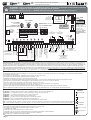 2
2
-
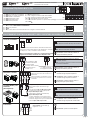 3
3
-
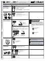 4
4
-
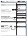 5
5
-
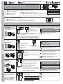 6
6
-
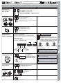 7
7
-
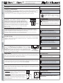 8
8
-
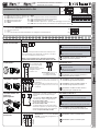 9
9
-
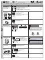 10
10
-
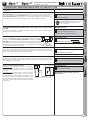 11
11
-
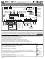 12
12
-
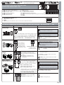 13
13
-
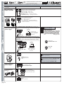 14
14
-
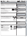 15
15
-
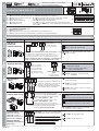 16
16
-
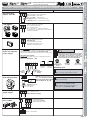 17
17
-
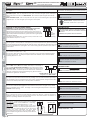 18
18
-
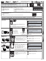 19
19
-
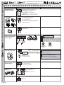 20
20
-
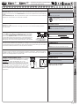 21
21
-
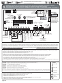 22
22
-
 23
23
-
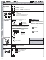 24
24
-
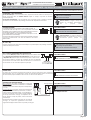 25
25
-
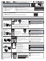 26
26
-
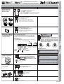 27
27
-
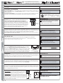 28
28
-
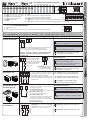 29
29
-
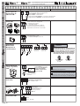 30
30
-
 31
31
-
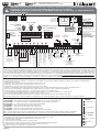 32
32
-
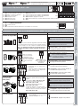 33
33
-
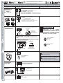 34
34
-
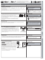 35
35
-
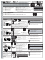 36
36
-
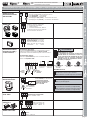 37
37
-
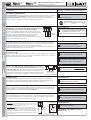 38
38
-
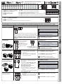 39
39
-
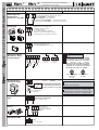 40
40
-
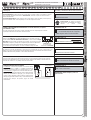 41
41
-
 42
42


dans d''autres langues
- italiano: Fadini elpro-x-xe
- español: Fadini elpro-x-xe
Documents connexes
-
Fadini elpro27hp230V Instructions Manual
-
-
-
-
-
-
-
-