
I254 Rev. D / MFP9720128
22 April 2013

1.0 Purpose..................................................................................... 3
2.0 General Requirements, Warnings and Limitations.................... 4-5
2.1 General Requirements
2.2 System Warnings and Limitations
3.0 System Diagram & Components, Assembly and Installation.... 5-10
3.1 Techline HLL System w/Cross-Arm Straps................................ 6-7
3.2 Techline Residential HLL System w/RA30-2 Roof Anchors.... 8-10
4.0 Training..................................................................................... 11
5.0 Inspection.................................................................................. 11-12
6.0 Fall Clearance........................................................................... 12-15
7.0 Care, Maintenance and Storage............................................... 15
Product Labels.......................................................................... 16-17
Inspection and Maintenance Log.............................................. 18
Warranty.................................................................................... 19
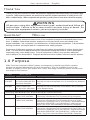
Table of Contents

User Instructions - English
3
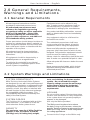
1.0 Purpose
Miller TechLine Horizontal Lifeline Systems are temporary horizontal rope lifeline systems
designed to provide fall protection for up to two workers. Kits are available for one or two
workers in lengths of 30 ft. (9m) and/or 60 ft. (18m); anchorage connector options include cross-
arm straps or roof anchors.
Questions? CALL
1.800.873.5242
It is crucial that the authorized person/user of this equipment read and understand these instruc-
tions. In addition, federal law requires employers to ensure that all users are trained in the
proper installation, use, inspection, and maintenance of fall protection equipment. Fall protection
training should be an integral part of a comprehensive safety program.
Proper use of fall arrest systems can save lives and reduce the potential of serious injuries from
a fall. The user must be aware that forces experienced during the arrest of a fall or prolonged
suspension may cause bodily injury. Consult a physician if there is any question about the
user’s ability to use this product. Pregnant women and minor children must not use this product.
Thank you for your purchase of Miller fall protection equipment manufactured by Honeywell Safety
Products. Miller brand products are produced to meet the highest standards of quality at our ISO
FHUWL¿HGIDFLOLW\0LOOHUHTXLSPHQWZLOOSURYLGH\RXZLWK\HDUVRIXVHZKHQFDUHGIRUSURSHUO\
Thank You
All persons using this equipment must read, understand and follow all
instructions. Failure to do so may result in serious injury or death. Do
not use this equipment unless you are properly trained.
WARNING
!
SKU Description Kit Contents
TechLine HLL Kits with Cross-Arm Straps
HLLR1/30FT
HLLR1/60FT Temporary Rope HLL System
for 1 worker; available with 30 ft.
(9m) or 60 ft. (18m) lifeline
11/16-in. (17.5mm) kernmantle-style rope lifeline / Lifeline adjuster / Two (2)
heavy-duty cross-arm anchorage straps / One (1) connecting O-ring / Waterproof
bucket
HLLR2/30FT
HLLR2/60FT Temporary Rope HLL System for
2 workers; available with
30 ft. (9m) or 60 ft. (18m) lifeline
11/16-in. (17.5mm) kernmantle-style rope lifeline / Lifeline adjuster / Two (2)
heavy-duty cross-arm anchorage straps / Shock absorber / Two (2) connecting
O-rings / Waterproof bucket
Add a “-Z7” before the “/” for 3600 lb. gate snap hooks.
TechLine Residential HLL Kits with RA30-2 Roof Anchors
HLLR0/RR60FT Temporary Rope HLL System for
2 workers; 60 ft. (18m) lifeline 11/16-in. (17.5mm) kernmantle-style rope lifeline / Lifeline adjuster / Two (2) RA30-
2 roof anchors / Shock absorber / Two (2) connecting O-rings / Storage bag
HLLR1/RR60FT Temporary Rope HLL System for
2 workers; 60 ft. (18m) lifeline 11/16-in. (17.5mm) kernmantle-style rope lifeline / Lifeline adjuster / Two (2) RA30-
2 roof anchors / Shock absorber / Two (2) connecting O-rings / One (1) Titan™
full-body harness (T4000/UAK) / One (1) 3 ft. (0.9m) Titan™ lanyard with SofStop®
shock absorber (T6111/3FTAF) / One (1) Miller MicroLoc™ trailing rope grab
(8173/U) / One (1) 50 ft. (15m) vertical lifeline (300C/50FTBL) / Storage bag
HLLR2/RR60FT Temporary Rope HLL System for
2 workers; 60 ft. (18m) lifeline 11/16-in. (17.5mm) kernmantle-style rope lifeline / Lifeline adjuster / Two (2) RA30-
2 roof anchors / Shock absorber / Two (2) connecting O-rings / Two (2) Titan™ full-
body harnesses (T4000/UAK) / Two (2) 3 ft. (0.9m) Titan™ lanyards with SofStop®
shock absorber (T6111/3FTAF) / Two (2) Miller MicroLoc™ trailing rope grabs
(8173/U) / Two (2) 50 ft. (15m) vertical lifelines (300C/50FTBL) / Storage bag

User Instructions - English
4
SYSTEM COMPATIBILTY
Miller TechLine Horizontal Lifeline Systems
are designed for use with Honeywell-approved
components. Substitution or replacement with
non-approved component combinations, sub-
systems, or both, may affect or interfere with
the safe function of each other and endanger
the compatibility within the system. This
incompatibility may affect the reliability and
safety of the total system.
SYSTEM FORCES
The TechLine HLL is equipped with an inline
shock absorber. In the event of a fall, the
shock absorber limits system forces.
CAPACITY
The maximum capacity of Miller TechLine
Systems is two (2) workers at 310 lbs
(140.6kg) each, including body weight,
Equipment must not be altered in any
way. Repairs must be performed only by
the manufacturer, or persons or entities
authorized in writing by the manufacturer.
Any product exhibiting deformities, unusual
wear, or deterioration must be immediately
discarded.
Any equipment subject to a fall must be
removed from service.
The authorized person/user shall have
a rescue plan and the means at hand to
implement it when using this equipment.
Never use fall protection equipment for
purposes other than those for which it was
designed. Fall protection equipment should
never be used for towing or hoisting.
Always check for obstructions below the work
area to make sure potential fall path is clear.
Allow adequate fall clearance below the work
surface.
Never remove product labels, which include
important warnings and information for the
authorized person/user.
2.2 System Warnings and Limitations
tools, and clothing, for the two-worker
system. Do not exceed this weight.
Capacity ratings assume the anchorage
or structure to which the horizontal
lifeline kit is installed meets the load
requirements.
LIFELINE
Do not use this system if the tensioner does
not lock onto the lifeline or if any component
in the system does not operate properly or
appears to be damaged.
Use only the lifeline provided.
The lifeline must be placed at or above
the back D-ring on the harness, unless the
VSHFL¿F7HFK/LQH6\VWHPLVDSSURYHGIRUXVH
below the D-ring, such as those designated
IRUURR¿QJDSSOLFDWLRQV
Connect to the O-rings on the lifeline only.
All warnings and instructions shall be
provided to authorized persons/users.
All authorized persons/users must
reference the regulations governing
occupational safety, as well as applicable
ANSI or CSA standards. Please refer
to product labeling for information on
VSHFL¿F26+$UHJXODWLRQVDQG$16,DQG
CSA standards met by product.
Proper precautions should always be taken to
remove any obstructions, debris, material, or
other recognized hazards from the work area
that could cause injuries or interfere with the
operation of the system.
All equipment must be inspected before
each use according to the manufacturer’s
instructions.
All equipment should be inspected by a
TXDOL¿HGSHUVRQRQDUHJXODUEDVLV
To minimize the potential for accidental
disengagement, a competent person must
ensure system compatibility.
2.0 General Requirements,
Warnings and Limitations
2.1 General Requirements

User Instructions - English
5
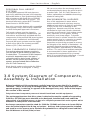
3.0 System Diagram of Components,
Assembly & Installation
Before installation of this equipment, carefully inspect to ensure that it is in useable
condition. Check for missing or damaged parts. Do not use if any component does not
operate properly, is missing, or appears to be damaged in any way. Refer to the inspec-
tion section of this manual.
2QO\WUDLQHGDQGFRPSHWHQWSHUVRQQHOVKRXOGLQVWDOODQGXVHWKLVHTXLSPHQW
The anchorage/structure that this system is attached to must be capable of supporting
5,000 lbs. (22.2 kN) per user attached; or be designed, installed and used, under the
VXSHUYLVLRQRIDTXDOL¿HGSHUVRQDVSDUWRIDFRPSOHWHSHUVRQDOIDOODUUHVWV\VWHPZKLFK
maintains a safety factor of at least two.
Anchorage connectors must be rated for 5,000 lbs (22.2kN) and chosen to locate lifeline
at or above the height of the D-ring on harness. Anchors and system must be installed
and used in such a manner as to minimize the potential for a swing fall hazard and limit
free fall distance to 6 feet (1.8m) or less.
PERSONAL FALL ARREST
SYSTEMS
A Honeywell-approved full-body harness
and shock-absorbing lanyard, self-retracting
lifeline/fall limiter or rope grab/vertical lifeline
with a maximum fall arrest force of 900 lbf
(4kN) must be used with this system. The
personal fall arrest system MUST limit fall
arrest forces to 900 lbf (4kN).
Use only connecting devices with compatible
locking snap hooks, auto-locking carabiners,
or other Honeywell-approved connectors.
Fall arrest systems must be rigged in
accordance to regulatory requirements. [All
instructions and warnings provided with the
components of the personal fall arrest system
must be read, understood, and followed.]
Personal fall arrest systems must be rigged
to limit a free fall to the shortest possible
distance [6 ft (1.8m) maximum].
FALL CLEARANCE & SWING FALL
Ensure that adequate clearance exists in
your fall path to avoid striking a lower level
or obstruction. The amount of fall clearance
required is dependent upon the type of
connecting device being used, number of
workers on the system, the length of the
V\VWHPDQGDVVRFLDWHGOLIHOLQHGHÀHFWLRQ
(see 6.0 Fall Clearance).
Work directly under or along side the lifeline
to avoid hazards of a swing fall. A swing
fall can occur when the anchorage point is
not located directly above the point at which
a worker falls. See 6.0 Fall Clearance for
further explanation and additional warnings
related to swing falls.
ENVIRONMENTAL HAZARDS
Use of this equipment in areas where
environmental hazards exist may require
additional precautions to limit the possibility
of injury to the user or damage to the
equipment. Hazards may include, but are
not limited to high heat, caustic chemicals,
corrosive environments, high-voltage power
lines, explosive or toxic gases, moving
machinery, and sharp edges. Polyester
should be used in certain chemical or acidic
environments. Use in a corrosive or caustic
environment dictates a more frequent
inspection and servicing program to ensure
the integrity of the device is maintained. All
synthetic material must be protected from
VODJKRWVSDUNVRSHQÀDPHVRURWKHUKHDW
sources. The use of heat resistant materials
is recommended in these applications. Do
not expose the equipment to any hazard
which it is not designed to withstand. Consult
the manufacturer in cases of doubt.which it
is not designed to withstand. Consult the
manufacturer in cases of doubt.

User Instructions - English
6
AA
BFGE
D
C
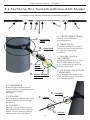
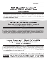
3.1 TechLine HLL System w/Cross-Arm Straps
(Complete system diagram shortened for illustration purposes)
E. CARABINER
Auto-locking carabiner used to
connect the end of the lifeline to an
approved anchorage
connector.
F. LIFELINE
5/8” (15.9mm) polyester rope used
to span between two anchorage
connectors.
G. O-RINGS
Used to connect worker’s shock-
absorbing lanyard, self-retracting
lifeline, or rope grab and vertical
lifeline to the horizontal lifeline.
A. CROSS-ARM STRAPS
Used to secure lifeline to
anchorage point.
B. SNAP HOOK
Self-locking snap hook used to
connect the end of the lifeline to
an approved anchorage
connector.
C. IN-LINE SHOCK
ABSORBER
Designed to limit forces to 2,500
lbs (11.2kN), which provides
a 2:1 safety factor for 5,000 lb
(22.2kN) anchorage.
D. LIFELINE ADJUSTER/
TENSIONER
Used to adjust the length of the
rope, indicate proper pre-tension
and maintain tension.
G - 25LQJV
E - Carabiner
F - Lifeline
B - Snap Hook
D - Lifeline Adjuster/
Tensioner
A - Cross-Arm
Straps
C - In-Line
Shock
Absorber

User Instructions - English
7
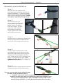
Step 1
Wrap a cross-arm strap around
each approved anchorage point for the
system installation. To prevent slippage,
wrap cross-arm strap around anchorage
point as many times as possible. D-ring
must pass completely through loop.
Step 2
Secure snap hook (on
shock absorber lifeline end)
and carabiner (on opposite
lifeline end) to D-rings on
cross-arm straps. Be sure
snap hook and carabiner
are properly connected--
closed and locked--and no
gate loading is present.
Step 4
Tension the line with wrench or bar
E\SXOOLQJ¿UPO\RQWKHIUHHHQGRIWKH
rope while at the same time turning the
tensioner nut in the direction of the ar-
row. Tighten nut (1-3/16”) until tensioner
begins to slip against the rope. Once
slippage occurs, DO NOT continue to
tighten the tensioner.
Step 3
Remove slack in system by releasing the
tension release lever and pull the free
end of the rope through the tensioner.
Step 5
Close the tension release lever to prevent
unintentional loosening of line tension.
Assembly and Installation
)RUXVHFRQQHFWRQO\WRRQHRIWKH2ULQJV
provided on the horizontal lifeline.
'2127FRQQHFWWRERWK2ULQJVZLWKRQHFRQQHFWLQJGHYLFH
'2127FRQQHFWPRUHWKDQRQHFRQQHFWLQJGHYLFHWRDVLQJOH2ULQJ
Use only connecting devices with compatible locking snap hooks,
auto-locking carabiners, or other Honeywell-approved connectors.

User Instructions - English
8
AA
BFG
E
D
C
G - 25LQJV
E - Carabiner
F - Lifeline
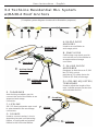
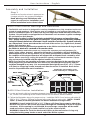
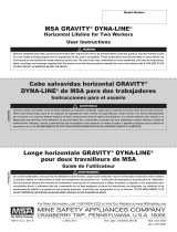
3.2 TechLine Residential HLL System
w/RA30-2 Roof Anchors
(Complete system diagram shortened for illustration purposes)
B - Snap Hook
D - Lifeline Adjuster/
Tensioner
A - RA30-2 Roof
Anchors
E. CARABINER
Auto-locking carabiner used to
connect the end of the lifeline to an
approved anchorage
connector.
F. LIFELINE
5/8” (15.9mm) polyester rope used
to span between two anchorage
connectors.
G. O-RINGS
Used to connect worker’s shock-
absorbing lanyard, self-retracting
lifeline, or rope grab and vertical
lifeline to the horizontal lifeline.
C - In-Line Shock
Absorber
A. RA30-2 ROOF
ANCHORS
Used to secure lifeline to
anchorage point.
B. SNAP HOOK
Self-locking snap hook used to
connect the end of the lifeline to
an approved anchorage
connector.
C. IN-LINE SHOCK
ABSORBER
Designed to limit forces to 2,500
lbs (11.2kN), which
provides a 2:1 safety factor for
5,000 lb (22.2kN) anchorage.
D. LIFELINE ADJUSTER/
TENSIONER
Used to adjust the length of the
rope, indicate proper pre-tension
and maintain tension.

User Instructions - English
9
Step 1
Install a roof anchor at each approved an-
chorage point for the system installation.
Read warnings and limitations with
regard to roof anchor installation, and
follow installation instructions below.
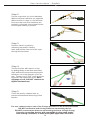
Assembly and Installation
RA30-2 Roof Anchor Warnings and Limitations
7KH5$URRIDQFKRULVGHVLJQHGIRUURRIWRSLQVWDOODWLRQVRQIXOO\VKHDWKHGURRIVFRP-
SULVHGRIZRRGPHPEHUV5RRIDQFKRUPD\EHLQVWDOOHGRQURRISHDNVRUÀDWURRIVDQG
must be installed at least 6 ft. (1.8m) from any roof edge when used with the Techline HLL
System. Do not install on unsupported roof structures such as eaves or gable overhangs.
Do not install on facia boards.
Roof anchor location is critical to minimize potential fall clearance and possible swing
falls. Always avoid a possible gable end swing fall. Locate anchors so that any potential
swing fall hazards have been eliminated. Never install the Techline HLL System vertically
on a sloped roof. Never work above the roof level of the anchor (i.e., higher level, dormer,
higher roof structure, etc.).
5RRIDQFKRUPXVWEHSRVLWLRQHGSHUSHQGLFXODUWRWKHOLIHOLQHVXFKWKDWWKH2ULQJWRZKLFK
the lifeline is attached is centered on the anchor chain.
%HIRUHLQVWDOODWLRQDQGEHIRUHHDFKXVHLQVSHFWWKHVWUXFWXUHDQGURRIPHPEHUVLH
studs, joists, rafters, trusses), where the roof anchor is installed or will be installed for
deteriorated wood, rot, decay, defects, or any other questionable conditions. Ensure that
the condition of the support structure will support the anticipated loads created by a fall
DUUHVW%HIRUHXVHRIDQ\URR¿QJIDOOSURWHFWLRQV\VWHPHQVXUHWKDWWKHDQFKRULVSURS-
erly and securely installed with the required number of fasteners.
RA30-2 roof anchors are reusable anchorage connectors designed to be repositioned as
work progresses, provided that the roof anchor has not seen fall arrest forces and has
not been damaged in any way. It is recommended that eight (8) new 5/16” x 2-½” (7.9mm
x 63.5mm) or longer lag screws be used each time the anchor is installed. Roof anchor
must be inspected before each installation.
RA30-2 Roof Anchor Installation
1. Locate and mark solid roof members/support structures (i.e., studs, joists, rafters, trusses,
etc.) under roof sheathing at the location where the roof anchor will be installed.
2. Follow the illustration above for proper set-up. Install the RA30-2 roof anchor with eight (8)
5/16” x 2-½” (7.9mm x 63.5mm) or longer lag screws (four on each side). NOTE: Predrill
13/64” (5.2mm) or smaller pilot holes for easier installation of lag screws.
WARNING: Use all eight (8) 5/16” x 2-½” (7.9mm x 63.5mm) lag screws to attach the
RA30-2 roof anchor. All screws must pass through the sheathing and into a support
structure. If this warning is not followed, the anchorage connection will be weak-
ened and serious injury or death could occur in the event of a fall.
WARNING: Attach the TechLine Horizontal Lifeline to the roof anchor O-ring only
using the locking snap hooks on each end of the lifeline system.
SHEATHING
LAG SCREWS
ROOF PEAK
TRUSS/
RAFTER Connect to
O-RING only!
Install
6 ft. (1.8m)
from Edge
Install HLL horizontally; never
install vertically on a sloped roof.

User Instructions - English
10
Step 2
Secure snap hook (on shock absorber
lifeline end) and carabiner (on opposite
lifeline end) to O-rings on roof anchors.
Be sure snap hook and carabiner are
properly connected--closed and locked--
and no gate loading is present.
Step 4
Tension the line with wrench or bar
E\SXOOLQJ¿UPO\RQWKHIUHHHQGRIWKH
rope while at the same time turning the
tensioner nut in the direction of the ar-
row. Tighten nut (1-3/16”) until tensioner
begins to slip against the rope. Once
slippage occurs, DO NOT continue to
tighten the tensioner.
Step 3
Remove slack in system by
releasing the tension release
lever and pull the free end of the rope
through the tensioner.
Step 5
Close the tension release lever to
prevent unintentional loosening of line
tension.
)RUXVHFRQQHFWRQO\WRRQHRIWKH2ULQJVSURYLGHGRQWKHKRUL]RQWDOOLIHOLQH
'2127FRQQHFWWRERWK2ULQJVZLWKRQHFRQQHFWLQJGHYLFH
'2127FRQQHFWPRUHWKDQRQHFRQQHFWLQJGHYLFHWRDVLQJOH2ULQJ
Use only connecting devices with compatible locking snap hooks,
auto-locking carabiners, or other Honeywell-approved connectors.

User Instructions - English
11
4.0 Training
5.0 Inspection
It is the responsibility of the user and the purchaser of this equipment to assure they are familiar
with these instructions and are trained in the proper use, installation, operation, maintenance
and limitations of this product. Training should be conducted periodically and without exposing
the trainee to a fall hazard.
Training is an integral part of our Total Solution in fall protection, since no fall protection equip-
ment – regardless of how effective – can save an employee who is not trained in its use. To
meet this crucial requirement, Miller Training provides the knowledge and skills necessary to
achieve a safe, more productive work environment. For more information on Miller Training,
contact a representative today: 800.873.5242.
Miller TechLine Horizontal Lifeline Systems must be visually inspected by the user before
each use and inspected by a Competent Person on a regular basis, at least annually.
Perform the following procedures if applicable to your system and its components:
GENERAL PRODUCT INSPECTION
REQUIRED FOR ALL SYSTEM COMPONENTS
Inspect system and its components for any of the following: bent, cracked, distorted, worn,
malfunctioning or damaged parts; rough or sharp edges; loose fasteners or missing parts/
components; corrosion; deterioration; signs that indicate the product has been subjected to
a fall arrest; or any other indications of damage/problems that may affect the integrity and
operation of the component/system. If in doubt, contact the manufacturer.
Anchorage Connectors
Cross-Arm Straps: When inspecting the webbing, be sure to inspect each section,
URWDWLQJDQGÀH[LQJWRUHYHDODQ\GDPDJHFXWVEURNHQVWUDQGV¿EHUVIUD\HGDUHDV
pulled stitches, burns, environmental or chemical damage (refer to Table 1), unusual
wearing patterns, or signs of deterioration. Inspect hardware for distortion, cracks, breaks,
corrosion, pitted surfaces, and rough or sharp edges.
Roof Anchors: In addition to the general inspection, carefully inspect rivets, studs
and fasteners to ensure that all are present, securely tightened or clinched, and are not
damaged in any way. Check O-ring and chain for any damage, cracks, distortion, rough or
sharp edges. Chain must not be twisted or have any kinks. Anchor side plates should be
ÀDWDQGIUHHRIFRUURVLRQ
Horizontal Lifeline
When inspecting lifelines, begin at one end and work to the opposite end. Slowly rotate the
lifeline so that the entire circumference is checked. Inspect lifeline for cuts, frays, burns,
EURNHQ¿EHUVDQGH[FHVVLYHZHDU$OVRLQVSHFWIRUVLJQVRIHQYLURQPHQWDORUFKHPLFDO
damage (refer to Table 1).
Snap Hooks/Thimbles: Inspect closely for hook and eye distortions, cracks, breaks,
corrosion, pitted surfaces, and rough or sharp edges. The gate (keeper) should seat
into the nose without binding and should not be distorted or obstructed. The gate spring
VKRXOGH[HUWVXI¿FLHQWIRUFHWR¿UPO\FORVHWKHJDWH:KHQWKHJDWHLVFORVHGWKHORFNLQJ
PHFKDQLVP0867SUHYHQWWKHJDWHIURPRSHQLQJ7KHWKLPEOHPXVWEH¿UPO\VHDWHGLQ
the eye of the splice, and the splice should have no loose or cut strands. The edges of the
thimble must be free of sharp edges, distortion, or cracks.
Tensioner: Check tensioner for damage, cracks, wear, corrosion or malfunctioning
components. Ensure that it is operating properly and only as intented by the manufacturer.

User Instructions - English
12
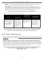
Refer to the Fall Clearance Diagram and to the following Fall Clearance Tables provided to obtain the
minimum Total Fall Clearance Required from the working surface or roof edge to the next lower level
or obstruction.
Important:%HVXUHWRUHIHUHQFHWKHFRUUHFWIDOOFOHDUDQFHWDEOHIRUWKHVSHFL¿FVRI\RXU7HFKOLQH
Horizontal Lifeline System and application. Fall clearance required depends on varying factors such
as the span length of the horizontal lifeline, the number of users on the system, and the connecting
device(s) being used. In addition, fall clearance requirements differ for the Techline HLL System with
Cross-Arm Straps and the Techline HLL System with RA30-2 Roof Anchors based on the installation
height of the system (above working surface vs. working surface level).
25LQJV O-rings must be present on the lifeline for attachment of the connecting device.
Check O-rings for any damage, cracks, distortion, rough or sharp edges.
Shock Absorber: The outer portion of the pack should be examined for burn holes and
tears. Stitching on areas where the pack is sewn to the webbing and hardware should be
examined for loose strands, rips, deterioration or other signs of activation. Pack-style shock
absorbers will break open to release the core contents when subjected to fall arrest forces. Any
signs of breakage, rips or tears should be noted as an indication of deployment.
For any missing, damaged or replacement parts call: 800.873.5242.
If inspection reveals a defect in condition or if components have
been subjected to fall arrest forces, remove the horizontal lifeline
system and all components from service immediately.
6.0 Fall Clearance
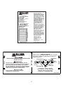
TABLE 1 - TYPES OF MATERIAL DAMAGE
HEAT CHEMICAL
MOLTEN
METAL OR
FLAME PAINTS AND
SOLVENTS
Paint which penetrates
and dries restricts
PRYHPHQWRI¿EHUV
Drying agents and
solvents in some
paints will appear as
chemical damage.
In excessive heat, rope/
webbing becomes brittle
and has a shriveled
brownish appearance.
Fibers will break when
ÀH[HG6KRXOGQRWEH
used above 180°F.
Change in color
usually appearing as
a brownish smear or
smudge. Transverse
cracks when rope/
webbing is bent over
a mandrel. Loss of
elasticity in rope/
webbing.
Rope/webbing strands
fuse together. Hard
shiny spots. Hard and
brittle feel.
If you have any questions about the fall clearance warnings and information provided in
this section, please contact Honeywell Technical Service immediately
at 800.873.5242 (press 4).

User Instructions - English
13
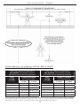
TECHLINE HLL SYSTEM w/ CROSS ARM STRAPS
FALL CLEARANCE TABLES
Total Fall Clearance Required for
one worker connected to system
with Miller shock-absorbing lanyard.
Span
Length
(in Feet)*
Length of Lanyard
(in Feet & Inches)
3 (0.9m) 6 (1.8m)
0-10 (0-3m) 14’-1” (4.29m) 17’-1” (5.18m)
11-20 (3.4-6.1m) 14’-8” (4.47m) 17’-8” (5.38m)
21-30 (6.4-9.1m) 15’-3” (4.65m) 18’-3” (5.56m)
31-40 (9.4-12.2m) 15’-10” (4.83m) 18’-10” (5.74m)
41-50 (12.5-15.2m) 16’-5” (5m) 19’-5” (5.92m)
51-60 (15.5-18.2m) 17’-1” (5.18m) 20’-1” (6.12m)
Total Fall Clearance Required for
two workers connected to system
with Miller shock-absorbing lanyards.
Span
Length
(in Feet)*
Length of Lanyard
(in Feet & Inches)
3 (0.9m) 6 (1.8m)
0-10 (0-3m) 14’-1” (4.29m) 17’-1” (5.18m)
11-20 (3.4-6.1m) 14’-9” (4.5m) 17’-9” (5.41m)
21-30 (6.4-9.1m) 15’-8” (4.78m) 18’-8” (5.69m)
31-40 (9.4-12.2m) 16’-8” (5.08m) 19’-8” (5.99m)
41-50 (12.5-15.2m) 17’-7” (5.36m) 20’-7” (6.27m)
51-60 (15.5-18.2m) 18’-7” (5.66m) 21’-7” (6.58m)
FALL CLEARANCE DIAGRAM
(For illustration purposes only; Techline HLL System with cross-arm straps shown)
FALL
CLEARANCE
DIAGRAM
(
For illustration purposes onl
y
; Techline HLL
Sy
stem with cross-arm straps shown
)
*Span Lengths are provided in feet (meters); for lengths that fall between the span length ranges provided, round up or down to
the nearest span length using standard rounding rules. (Ex.: For 30’-5”, use the span length of 31-40 feet to determine required
fall clearance. For 50’-2”, use the span length of 41-50 feet to determine required fall clearance.)

User Instructions - English
14
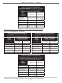
Total Fall Clearance Required for
one or two workers connected to system
with Miller self-retracting lifeline (SRL) or
Miller rope grab and vertical lifeline.
Span
Length
(in Feet)* 1 Worker 2 Workers
0-10 (0-3m) 14’-1” (4.29m) 14’-1” (4.29m)
11-20 (3.4-6.1m) 14’-8” (4.47m) 14’-9” (4.5m)
21-30 (6.4-9.1m) 15’-3” (4.65m) 15’-8” (4.78m)
31-40 (9.4-12.2m) 15’-10” (4.83m) 16’-7” (5.05m)
41-50 (12.5-15.2m) 16’-5” (5m) 17’-7” (5.36m)
51-60 (15.5-18.2m) 17’-1” (5.18m) 18’-7” (5.66m)
TECHLINE HLL SYSTEM w/ RA-30 ROOF ANCHORS
FALL CLEARANCE TABLES
Total Fall Clearance Required for
one worker connected to system
with Miller shock-absorbing lanyard.
Span
Length
(in Feet)*
Length of Lanyard
(in Feet & Inches)
3 (0.9m) 6 (1.8m)
0-10 (0-3m) 19’-1” (5.82m) 22’-1” (6.73m)
11-20 (3.4-6.1m) 19’-8” (5.99m) 22’-8” (6.91m)
21-30 (6.4-9.1m) 20’-3” (6.17m) 23’-3” (7.11m)
31-40 (9.4-12.2m) 20’-10” (6.35m) 23’-10” (7.26m)
41-50 (12.5-15.2m) 21’-5” (6.53m) 24’-5” (7.44m)
51-60 (15.5-18.2m) 22’-1” (6.73m) 25’-1” (7.65m)
Total Fall Clearance Required for
two workers connected to system
with Miller shock-absorbing lanyards.
Span
Length
(in Feet)*
Length of Lanyard
(in Feet & Inches)
3 (0.9m) 6 (1.8m)
0-10 (0-3m) 19’-1” (5.82m) 22’-1” (6.73m)
11-20 (3.4-6.1m) 19’-9” (6.02m) 22’-9” (6.93m)
21-30 (6.4-9.1m) 20’-8” (6.3m) 23’-8” (7.21m)
31-40 (9.4-12.2m) 21’-8” (6.6m) 24’-8” (7.52m)
41-50 (12.5-15.2m) 22’-7” (6.88m) 25’-7” (7.8m)
51-60 (15.5-18.2m) 23’-7” (7.19m) 26’-7” (8.1m)
Total Fall Clearance Required for
one or two workers connected to system
with Miller self-retracting lifeline (SRL) or
Miller rope grab and vertical lifeline.
Span
Length
(in Feet)* 1 Worker 2 Workers
0-10 (0-3m) 19’-1” (5.82m) 19’-1” (5.82m)
11-20 (3.4-6.1m) 19’-8” (5.99m) 19’-9” (6.02m)
21-30 (6.4-9.1m) 20’-3” (6.17m) 20’-8” (6.3m)
31-40 (9.4-12.2m) 20’-10” (6.35m) 21’-7” (6.58m)
41-50 (12.5-15.2m) 21’-5” (6.53m) 22’-7” (6.88m)
51-60 (15.5-18.2m) 22’-1” (6.73m) 23’-7” (7.19m)
*Span Lengths are provided in feet (meters); for lengths that fall between the span length ranges provided, round up or down to
the nearest span length using standard rounding rules. (Ex.: For 30’-5”, use the span length of 31-40 feet to determine required
fall clearance. For 50’-2”, use the span length of 41-50 feet to determine required fall clearance.)

User Instructions - English
15
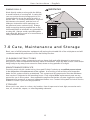
Basic care of all fall protection equipment will prolong the durable life of the unit/system and will
contribute toward the performance of its vital safety function.
CLEANING INSTRUCTIONS
Periodically clean system components using a damp cloth and mild detergent to remove any
dirt, paint, or other contaminants that may have accumulated. Wipe dry with a clean cloth and/or
hang freely to dry away from excessive heat, steam or long periods of sunlight.
MAINTENANCE/SERVICE
Servicing must only be carried out by Honeywell Safety Products RUDTXDOL¿HGSHUVRQWUDLQHG
in the inspection and replacement of the system. A record log of all servicing and inspection
dates for this system must be maintained. This system and all components must be withdrawn
from service if subjected to fall arresting forces. Only original Miller replacement parts are ap-
proved for use in this system. Non-repairable components that do not pass inspection must be
disposed of in a manner to prevent inadvertent further use. Contact Honeywell Technical Service
at 800.873.5242 if you have any questions.
STORAGE
When not in use, store in a clean, dry location, free of exposure to heat, light, excessive mois-
ture, oil, chemicals, vapors, or other degrading elements.
7.0 Care, Maintenance and Storage
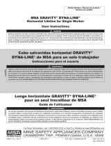
SWING FALL
SWING FALLS
Work directly under or along side the lifeline
to avoid hazards of a swing fall. A swing fall
can occur when the anchorage point is not
located directly above the point at which a
worker falls. In a swing fall situation, required
fall clearance increases, and the force of
hitting an obstruction while swinging can
be great and cause serious injury. Always
keep connecting device perpedicular to the
horizontal lifeline to minimize any potential for
a swing fall. Always avoid a possible gable
end swing fall. Never work in an area where a
swing fall hazard exists.
WARNING
!

16
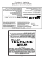
Product Labels
Étiquettes sur les Produits
Etiquetas de los Productos
If used for fall protection, a Miller shock-absorbing lanyard or self-retracting
lifeline must be used.
Inspect all components before each use.
Remove from service if any damage is detected.
Users must be trained before using this system.
A rescue plan should be developed prior to use.
Connectors and anchorage points must be compatible and able to
support 5,000 lbs. (22kN).
The lifeline must be placed at or above the back D-ring on the harness, unless
WKHVSHFL¿F7HFK/LQH6\VWHPLVDSSURYHGIRUXVHEHORZWKH'ULQJVXFKDV
WKRVHGHVLJQDWHGIRUURR¿QJDSSOLFDWLRQV1RPRUHWKDQDIWPIUHHIDOO
LVDOORZHGE\26+$
Do not allow lifeline to contact sharp or abrasive surfaces, sparks, or
temperatures above 180 degrees F (82 degrees C).
D

17
LB1291 REV. A
TRUSS
ROOF PEAK
TRUSS
WARNING
Manufacturer’s instructions supplied with this
product at the time of shipment must be followed:
FAILURE TO DO SO MAY RESULT IN SERIOUS
INJURY OR DEATH! Anchorage/support structure
must be capable of supporting a 5,000 lb. (22kN)
static load or provide a 2:1 safety factor.
BEFORE USING
Inspect before each use according to
manufacturer’s instructions.
SHEATHING
LAG SCREWS
ROOF PEAK
TRUSS/
RAFTER Connect to
O-RING only!
Compliance: OSHA 1926.502
Max. Capacity: 310 lbs. (140,6kg)
Material: Steel, Copper, Nylon
Questions? Call 800-873-5242
Heavy-Duty Multiple-Use Roof Anchor
Model: RA30-2
INSTALLATION
Attach anchor with eight (8) 5/16” x 2-1/2” or longer
lag screws. Position so that fasteners attach to a
support structure.
L930 REV. A
Honeywell Safety Products
Franklin, PA USA
800-873-5242
08/15/10

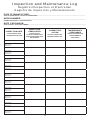
18
,163(&7,21'$7(
'$7('¶,163(&7,21
FECHA DE INSPECCIÓN
,163(&7,21
,7(06127('
P2,176127e6
/256'(/¶,163(&7,21
P81726'(,163(&&,Ï1
RELEVANTES
&255(&7,9(
$&7,21
A&7,21&255(&7,9(
M(','$&255(&7,9$
MAINTENANCE
3(5)250('
E175(7,(1())(&78e
M$17(1,0,(172
5($/,=$'2
Approved by:
Approuvé par:
Aprobado por:
Approved by:
Approuvé par:
Aprobado por:
Approved by:
Approuvé par:
Aprobado por:
Approved by:
Approuvé par:
Aprobado por:
Approved by:
Approuvé par:
Aprobado por:
Approved by:
Approuvé par:
Aprobado por:
Approved by:
Approuvé par:
Aprobado por:
Approved by:
Approuvé par:
Aprobado por:
Approved by:
Approuvé par:
Aprobado por:
Approved by:
Approuvé par:
Aprobado por:
'$7(2)0$18)$&785(_________________________________________________
'$7('()$%5,&$7,21)(&+$'()$%5,&$&,Ï1
02'(/180%(5_________________________________________________________
180e52'(02'Ê/(1Ò0'(02'(/2
DATE PURCHASED:______________________________________________________
'$7('¶$&+$7)(&+$'(&2035$
Inspection and Maintenance Log
Registre D'inspection et D'entretien
Registro de Inspección y Mantenimiento

19
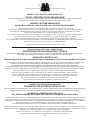
MILLER®)$//3527(&7,21352'8&76
727$/6$7,6)$&7,21$6685$1&(
At Honeywell Safety Products and its predecessors, we have been providing quality Miller brand
fall protection equipment to millions of workers worldwide since 1945.
LIMITED LIFETIME WARRANTY
BACKED BY OVER 65 YEARS IN THE FALL PROTECTION BUSINESS
We sincerely believe that our fall protection equipment is the best in the world.
Our products endure rigorous tests to ensure that the fall protection equipment you trust is manufactured
to the highest standards. Miller fall protection products are tested to withstand normal wear and tear,
but are not indestructible and can be damaged by misuse.
Our Limited Lifetime Warranty does not apply to normal wear and tear or abusive treatment of the product.
In the unlikely event that you should discover defects in either workmanship or materials,
under our Limited Lifetime Warranty, we will repair or replace the product at our expense.
If a replacement is necessary and your product is no longer available, a comparable product will be substituted.
Should a product issue surface, contact us at 800.873.5242.
0DQXIDFWXULQJVSHFL¿FDWLRQVDUHVXEMHFWWRFKDQJHZLWKRXWQRWLFH
352'8,760,//(5®)$//3527(&7,21
$6685$1&('(6$7,6)$&7,21727$/(
Honeywell Safety Products et ses prédécesseurs offrent les équipements antichute de marque Miller
de qualité à des millions de travailleurs dans le monde entier depuis 1945.
*$5$17,(/,0,7e(¬9,(
ASSURÉE GRÂCE À PLUS DE 65 ANS PASSÉS DANS LE DOMAINE DE LA PROTECTION CONTRE LES CHUTES
Nous croyons sincèrement que notre équipement de protection contre les chutes est le meilleur au monde. Nos
SURGXLWVVRQWVRXPLVjGHVWHVWVULJRXUHX[D¿QG¶DVVXUHUTXHOHVpTXLSHPHQWVGHSURWHFWLRQFRQWUH
OHVFKXWHVGDQVOHVTXHOVYRXVDYH]FRQ¿DQFHVRQWIDEULTXpVVHORQOHVQRUPHVOHVSOXVH[LJHDQWHV
/HVSURGXLWVGHSURWHFWLRQFRQWUHOHVFKXWHV0LOOHUVRQWVRXPLVjGHVHVVDLVSRXUYpUL¿HUTX¶LOVUpVLVWHQWjXQHXVXUH
normale; ils ne sont cependant pas indestructibles et peuvent s’endommager en cas de mauvaise utilisation. Notre
garantie limitée à vie ne s’applique pas à l’usure normale ou à un usage abusif du produit.
Dans le cas peu probable où vous découvririez des défauts, soit de fabrication, soit de matériau,
dans le cadre de notre garantie à vie, nous réparerons ou remplacerons le produit à nos frais.
En cas de remplacement, si votre produit n’est plus offert, vous recevrez un produit comparable.
En cas de problème sur un produit, nous contacter au 800-873-5242.
/HVFDUDFWpULVWLTXHVGHIDEULFDWLRQSHXYHQWrWUHPRGL¿pHVVDQVSUpDYLV
352'8&726$17,&$Ë'$60,//(5®
*$5$17Ë$'(6$7,6)$&&,Ï1727$/
En Honeywell Safety Products y sus predecesores, hemos estado brindando la calidad de la marca Miller en
equipos de protección de caída a millones de trabajadores alrededor del mundo desde 1945.
*$5$17Ë$/,0,7$'$'(3259,'$
NOS RESPALDAN MÁS DE 65 AÑOS EN LA FABRICACIÓN DE EQUIPO ANTICAÍDAS
Sinceramente creemos que su equipo de protección contra caídas es el mejor del mundo. Nuestros productos resisten
rigurosas pruebas para garantizar que el equipo de protección contra caídas en el que usted confía está fabricado de
conformidad con las normas más elevadas. Los productos anticaídas Miller son sometidos a pruebas para que resistan el
desgaste normal, pero no son indestructibles y su incorrecta utilización puede dañarlos.
Nuestra Garantía limitada de por vida no se aplica al desgaste normal ni al maltrato del producto.
En el poco probable caso de que usted descubriera defectos de mano de obra o materiales, por nuestra Garantía lim-
itada de por vida, repararemos o sustituiremos el producto por cuenta nuestra. Si un reemplazo es necesario y nuestro
producto ya no está disponible, se lo sustituiremos por otro comparable.
En caso de que surja un problema con el producto, contáctenos al 800.873.5242.
/DVHVSHFL¿FDFLRQHVGHIDEULFDFLyQHVWiQVXMHWDVDPRGL¿FDFLRQHVVLQSUHYLRDYLVR

Honeywell Safety Products
P.O. Box 271, 1345 15th Street
Franklin, PA 16323 USA
Toll Free: 800.873.5242
Fax: 800.892.4078
Download this manual at: www.millerfallprotection.com
Téléchargez ce manuel à l’adresse: www.millerfallprotection.com
Puede bajar por Internet este manual en: www.millerfallprotection.com
-
 1
1
-
 2
2
-
 3
3
-
 4
4
-
 5
5
-
 6
6
-
 7
7
-
 8
8
-
 9
9
-
 10
10
-
 11
11
-
 12
12
-
 13
13
-
 14
14
-
 15
15
-
 16
16
-
 17
17
-
 18
18
-
 19
19
-
 20
20


dans d''autres langues
- English: Miller HLLR Series User manual
Autres documents
-
Honeywell 26350 Manuel utilisateur
-
 Dyna-Line Gravity® Temporary Horizontal Lifelines Le manuel du propriétaire
-
3M 7611907 Mode d'emploi
-
3M DBI-SALA® Roof Top Anchor 2100138, 1 EA Mode d'emploi
-
-
-
 Dyna-Line Gravity® Temporary Horizontal Lifelines Le manuel du propriétaire
-
 Dyna-Line Gravity® Temporary Horizontal Lifelines Le manuel du propriétaire
-
-


