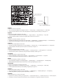
Hitachi RAS-(4-6)H(V)NC1E Manuel utilisateur
- Catégorie
- Climatiseurs split-system
- Taper
- Manuel utilisateur
Ce manuel convient également à

UTOPIA IVX STANDARD Series
RAS-(4-6)H(V)NC1E
INSTRUCTION MANUAL
MANUAL DE INSTRUCCIONES
BEDIENUNGSANLEITUNG
MANUEL D’UTILISATION
MANUALE DI ISTRUZIONI
MANUAL DE INSTRUÇÕES
BRUGSANVISNING
INSTALLATIEHANDLEIDING
INSTALLATIONSHANDBOK
ΕΓΧΕΙΡΊΔΙΟ ΟΔΗΓΙΏΝ


English
Specications in this manual are subject to change without notice in order that HITACHI may bring the latest innovations
to their customers.
Whilst every effort is made to ensure that all specications are correct, printing errors are beyond Hitachi’s control;
Hitachi cannot be held responsible for these errors.
Español
Las especicaciones de este manual están sujetas a cambios sin previo aviso a n de que HITACHI pueda ofrecer las
últimas innovaciones a sus clientes.
A pesar de que se hacen todos los esfuerzos posibles para asegurarse de que las especicaciones sean correctas, los
errores de impresión están fuera del control de HITACHI, a quien no se hará responsable de ellos.
Deutsch
Bei den technischen Angaben in diesem Handbuch sind Änderungen vorbehalten, damit HITACHI seinen Kunden die
jeweils neuesten Innovationen präsentieren kann.
Sämtliche Anstrengungen wurden unternommen, um sicherzustellen, dass alle technischen Informationen ohne Fehler
veröffentlicht worden sind. Für Druckfehler kann HITACHI jedoch keine Verantwortung übernehmen, da sie außerhalb
ihrer Kontrolle liegen.
Français
Les caractéristiques publiées dans ce manuel peuvent être modiées sans préavis, HITACHI souhaitant pouvoir toujours
offrir à ses clients les dernières innovations.
Bien que tous les efforts sont faits pour assurer l’exactitude des caractéristiques, les erreurs d’impression sont hors du
contrôle de HITACHI qui ne pourrait en être tenu responsable.
Italiano
Le speciche di questo manuale sono soggette a modica senza preavviso afnché HITACHI possa offrire ai propri
clienti le ultime novità.
Sebbene sia stata posta la massima cura nel garantire la correttezza dei dati, HITACHI non è responsabile per eventuali
errori di stampa che esulano dal proprio controllo.
Português
As especicações apresentadas neste manual estão sujeitas a alterações sem aviso prévio, de modo a que a HITACHI
possa oferecer aos seus clientes, da forma mais expedita possível, as inovações mais recentes.
Apesar de serem feitos todos os esforços para assegurar que todas as especicações apresentadas são correctas,
quaisquer erros de impressão estão fora do controlo da HITACHI, que não pode ser responsabilizada por estes erros
eventuais.
Dansk
Specikationerne i denne vejledning kan ændres uden varsel, for at HITACHI kan bringe de nyeste innovationer ud til
kunderne.
På trods af alle anstrengelser for at sikre at alle specikationerne er korrekte, har Hitachi ikke kontrol over trykfejl, og
Hitachi kan ikke holdes ansvarlig herfor.
Nederlands
De specicaties in deze handleiding kunnen worden gewijzigd zonder verdere kennisgeving zodat HITACHI zijn klanten
kan voorzien van de nieuwste innovaties.
Iedere poging wordt ondernomen om te zorgen dat alle specicaties juist zijn. Voorkomende drukfouten kunnen echter
niet door Hitachi worden gecontroleerd, waardoor Hitachi niet aansprakelijk kan worden gesteld voor deze fouten.
Svenska
Specikationerna i den här handboken kan ändras utan föregående meddelande för att HITACHI ska kunna leverera de
senaste innovationerna till kunderna.
Vi på Hitachi gör allt vi kan för att se till att alla specikationer stämmer, men vi har ingen kontroll över tryckfel och kan
därför inte hållas ansvariga för den typen av fel.
Eλλhnika
Οι προδιαγραφές του εγχειριδίου μπορούν να αλλάξουν χωρίς προειδοποίηση, προκειμένου η HITACHI να παρέχει τις
τελευταίες καινοτομίες στους πελάτες της.
Αν και έχει γίνει κάθε προσπάθεια προκειμένου να εξασφαλιστεί ότι οι προδιαγραφές είναι σωστές, η Hitachi δεν μπορεί
να ελέγξει τα τυπογραφικά λάθη και, ως εκ τούτου, δεν φέρει καμία ευθύνη για αυτά τα λάθη.

! CAUTION
This product shall not be mixed with general house waste at the end of its life and it shall be retired according to the appro-
priated local or national regulations in a environmentally correct way.
Due to the refrigerant, oil and other components contained in Air Conditioner, its dismantling must be done by a professio-
nal installer according to the applicable regulations. Contact to the corresponding authorities for more information.
! PRECAUCIÓN
Éste producto no se debe eliminar con la basura doméstica al nal de su vida útil y se debe desechar de manera respetuosa con el
medio ambiente de acuerdo con los reglamentos locales o nacionales aplicables.
Debido al refrigerante, el aceite y otros componentes contenidos en el sistema de aire acondicionado, su desmontaje debe realizarlo un
instalador profesional de acuerdo con la normativa aplicable. Para obtener más información, póngase en contacto con las autoridades
competentes.
! VORSICHT
Dass Ihr Produkt am Ende seiner Betriebsdauer nicht in den allgemeinen Hausmüll geworfen werden darf, sondern entsprechend den
geltenden örtlichen und nationalen Bestimmungen auf umweltfreundliche Weise entsorgt werden muss.
Aufgrund des Kältemittels, des Öls und anderer in der Klimaanlage enthaltener Komponenten muss die Demontage von einem
Fachmann entsprechend den geltenden Vorschriften durchgeführt werden. Für weitere Informationen setzen Sie sich bitte mit den
entsprechenden Behörden in Verbindung.
! ADVERTISSEMENT
Ne doit pas être mélangé aux ordures ménagères ordinaires à la n de sa vie utile et qu’il doit être éliminé conformément à la réglemen-
tation locale ou nationale, dans le plus strict respect de l’environnement.
En raison du frigorigène, de l’huile et des autres composants que le climatiseur contient, son démontage doit être réalisé par un installa-
teur professionnel conformément aux réglementations en vigueur.
! AVVERTENZE
Indicazioni per il corretto smaltimento del prodotto ai sensi della Direttiva Europea 2002/96/EC e Dlgs 25 luglio 2005 n.151
Il simbolo del cassonetto barrato riportato sull’ apparecchiatura indica che il prodotto alla ne della propria vita utile deve essere raccolto
separatamente dagli altri riuti.
L’utente dovrà, pertanto, conferire l’apparecchiatura giunta a ne vita agli idonei centri di raccolta differenziata dei riuti elettronici ed
elettrotecnici, oppure riconsegnarla al rivenditore al momento dell’ acquisto di una nuova apparecchiatura di tipo equivalente.
L’adeguata raccolta differenziata delle apparecchiature dismesse, per il loro avvio al riciclaggio, al trattamento ed allo smaltimento
ambientalmente compatibile, contribuisce ad evitare possibili effetti negativi sull’ ambiente e sulla salute e favorisce il riciclo dei materiali
di cui è composta l’ apparecchiatura. Non tentate di smontare il sistema o l’unità da soli poichè ciò potrebbe causare effetti dannosi sulla
vostra salute o sull’ ambiente. Vogliate contattare l’ installatore, il rivenditore, o le autorità locali per ulteriori informazioni.
Lo smaltimento abusivo del prodotto da parte dell’utente può comportare l’applicazione delle sanzioni amministrative di cui all’articolo 50
e seguenti del D.Lgs. n. 22/1997.
! CUIDADO
O seu produto não deve ser misturado com os desperdícios domésticos de carácter geral no nal da sua duração e que deve ser elimi-
nado de acordo com os regulamentos locais ou nacionais adequados de uma forma correcta para o meio ambiente.
Devido ao refrigerante, ao óleo e a outros componentes contidos no Ar condicionado, a desmontagem deve ser realizada por um instala-
dor prossional de acordo com os regulamentos aplicáveis. Contacte as autoridades correspondentes para obter mais informações.
! ADVASEL!
At produktet ikke må smides ud sammen med almindeligt husholdningsaffald, men skal bortskaffes i overensstemmelse med de
gældende lokale eller nationale regler på en miljømæssig korrekt måde.
Da klimaanlægget indeholder kølemiddel, olie samt andre komponenter, skal afmontering foretages af en fagmand i overenss-
temmelse med de gældende bestemmelser.
Kontakt de pågældende myndigheder for at få yderligere oplysninger.
! VOORZICHTIG
Dit houdt in dat uw product niet wordt gemengd met gewoon huisvuil wanneer u het weg doet en dat het wordt gescheiden op een
milieuvriendelijke manier volgens de geldige plaatselijke en landelijke reguleringen.
Vanwege het koelmiddel, de olie en andere onderdelen in de airconditioner moet het apparaat volgens de geldige regulering door een
professionele installateur uit elkaar gehaald worden. Neem contact op met de betreffende overheidsdienst voor meer informatie.
! FÖRSIKTIGHET
Det innebär att produkten inte ska slängas tillsammans med vanligt hushållsavfall utan kasseras på ett miljövänligt sätt i enlighet med
gällande lokal eller nationell lagstiftning.
Luftkonditioneringsaggregatet innehåller kylmedium, olja och andra komponenter, vilket gör att det måste demonteras av en fackman i
enlighet med tillämpliga regelverk.
Ta kontakt med ansvarig myndighet om du vill ha mer information.
! ΠΡΟΣΟΧΗ
Σημαίνει ότι το προϊόν δεν θα πρέπει να αναμιχθεί με τα διάφορα οικιακά απορρίμματα στο τέλος του κύκλου ζωής του και θα πρέπει να
αποσυρθεί σύμφωνα με τους κατάλληλους τοπικούς ή εθνικούς κανονισμούς και με τρόπο φιλικό προς το περιβάλλον.
Λόγω του ψυκτικού, του λαδιού και άλλων στοιχείων που περιέχονται στο κλιματιστικό, η αποσυναρμολόγησή του πρέπει να γίνει από
επαγγελματία τεχνικό και σύμφωνα με τους ισχύοντες κανονισμούς.
Για περισσότερες λεπτομέρειες, επικοινωνήστε με τις αντίστοιχες αρχές.

English
Following Regulation EU No. 517/2014 on Certain Fluorinated Greenhouse gases, it is mandatory to ll in the label attached to the unit with the total amount
of refrigerant charged on the installation.
Do not vent R410A into the atmosphere: R410A are uorinated greenhouse gases covered by the Kyoto protocol global warming potential (GWP) R410A: =
2088.
Tn of CO2 equivalent of uorinated greenhouse gases contained is calculated by indicated GWP * Total Charge (in kg) indicated in the product label and
divided by 1000.
Español
De acuerdo con el reglamento UE Nº 517/2014 sobre determinados gases uorados de efecto invernadero, es obligatorio rellenar la etiqueta suministrada
con la unidad con la cantidad total de refrigerante con que se ha cargado la instalación.
No descargue el R410A en la atmósfera: R410A son gases uorados cubiertos por el protocolo de Kyoto con un potencial de calentamiento global (GWP):
= 2088.
Las Tn de CO2 equivalente de gases uorados de efecto invernadero contenidos se calcula por el PCA indicado * Carga Total (en kg) indicada en la etiqueta
del producto y dividida por 1000.
Deutsch
Folgende Verordnung EG Nr. 517/2014 Bestimmte uorierte Treibhausgase, auf dem Schild, das sich am Gerät bendet, muss die Gesamtkältemittelmenge
verzeichnet sein, die bei der Installation eingefüll wird.
Lassen sie R410A nicht in die luft entweichen: R410A sind uorierte treibhausgase, die durch das Kyoto-protokoll erfasst sind. Sie besitzen folgendes treib-
hauspotential (GWP) R410A: = 2088.
Die Menge an CO2-Äquivalent uorierte Treibhausgase enthalten (in Tn) wird von GWP * die auf dem Produktetikett angegebenen Gesamtfüllmenge (in kg)
und durch 1000 geteilt berechnet.
Français
En fonction de la Réglementation CE Nº 517/2014 concernant certains gaz à effet de serre uorés, il est obligatoire de remplir l'étiquette attachée à l'unité en
indiquant la quantité de uide frigorigène qui a été chargée à l'installation.
Ne laissez pas le R410A se répandre dans l'atmosphère: le R410A sont des gaz à effet de serre uorés, couverts par le protocole de Kyoto avec un potentiel
de rechauffement global (PRG) R410A: = 2088.
Les Tn d’équivalent-CO2 de gaz à effet de serre uorés contenus est calculé par le PRG * Charge Totale (en kg) indiquée dans l’étiquette du produit et divisé
par 1,000.
Italiano
In base alla Normativa EC Nº 517/2014 su determinati gas uorurati ad effetto serra, è obbligatorio compilare l'etichetta che si trova sull'unità inserendo la
quantità totale di refrigerante caricato nell'installazione.
Non scaricare R410A nell'atmosfera: R410A sono gas uorurati ad effetto serra che in base al protocollo di Kyoto presentano un potenziale riscaldamento
globale (GWP) R410A: = 2088.
Le Tn di CO2 equivalente di gas uorurati ad effetto serra contenuti si calcola dal GWP indicato * Carica Totale (in kg) indicato nella etichetta del prodotto e
diviso per 1000.
Português
Em conformidade com a Regulamentação da UE Nº 517/2014 sobre determinados gases uorados com efeito de estufa, é obrigatório preencher a etiqueta
axada na unidade com a quantidade total de refrigerante carregada na instalação.
Não ventilar R410A para a atmosfera: o R410A são gases uorados com efeito de estufa abrangidos pelo potencial de aquecimiento global (GWP) do pro-
tocolo de Quioto: = 2088.
Tn de CO2 equivalente de gases uorados com efeito de estufa é calculado pelo GWP indicado * Carga Total (em kg) indicado no rótulo de produto e dividido
por 1000.
Dansk
Henhold til Rådets forordning (EF) nr. 517/2014 om visse uorholdige drivhusgasser, skal installationens samlede mængde kølevæske fremgå at den etiket,
der er klæbet fast på enheden.
Slip ikke R410A ud i atmosfæren: R410A er uorholdige drivhus-gasser, der er omfattet af Kyoto-protokollens globale opvarmningspotentiale (GWP) R410A:
= 2088.
Tn af CO2-ækvivalent af uorholdige drivhusgasser er beregnet ved angivet GWP * Samlet Charge (i kg) er angivet i produktets etiket og divideret med 1000.
Nederlands
Conform richtlijn EC Nº 517/2014 voor bepaalde uorbroeikasgassen, dient u de tabel in te vullen op de unit met het totale koelmiddelvolume in de installatie.
Laat geen R410A ontsnappen in de atmosfeer: R410A zijn uorbroeikasgassen die vallen onder het protocol van Kyoto inzake klimaatverandering global
warming potential (GWP) R410A: = 2088.
Tn van CO2-equivalent van uorbroeikasgassen wordt berekend door het aangegeven GWP * Totale Hoeveelheid (in kg) aangegeven in het product label
en gedeeld door 1000.
Svenska
Enligt reglering EC Nº 517/2014 om vissa uorhaltiga växthusgaser, måste etiketten som sitter på enheten fyllas i med sammanlagd mängd kylmedium som
fyllts på under installationen.
Släpp inte ur R410A i atmosfären: R410A är uorhaltiga växthus-gaser som omfattas av Kyotoprotokollet om global uppvärmnings-potential (GWP) R410A:
= 2088.
Tn av CO2-ekvivalenter uorhaltiga växthusgaser beräknas genom indikeras GWP * Total Påfyllning (i kg) som anges i produktetiketten och divideras med
1000.
Eλλhnika
Σύμφωνα με τον Κανονισμό 517/2014/ΕΚ για για ορισμένα φθοριούχα αέρια θερμοκηπίου, είναι υποχρεωτική η συμπλήρωση της επισήμανσης που
επισυνάπτεται στη μονάδα με το συνολικό ποσό ψυκτικού που εισήχθη κατά την εγκατάσταση.
Μην απελευθερωνετε R410A στην ατμοσφαιρα. Τα R410A ειναι φθοριουχα αερια του θερμοκηπιου που εμπιπτουν στο πρωτοκολλο του κυοτο δυναμικο
θερμανσησ του πλανητη (GWP) R410A/R407C: = 2088
Tn ισοδύναμου CO2 φθοριούχων αερίων θερμοκηπίου που περιέχονται υπολογίζεται από υποδεικνύεται GWP * Συνολική πλήρωση (σε kg) που αναφέρεται
στην ετικέτα του προϊόντος και χωρίζονται από το 1000.

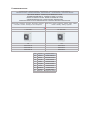
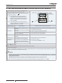
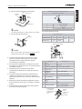
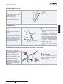
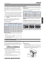
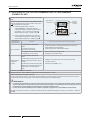
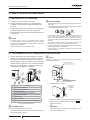
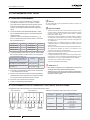
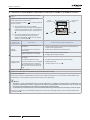
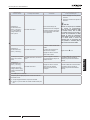
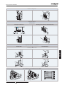
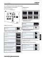
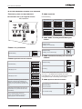
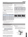
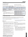
English
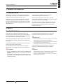
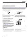
Instructions to ll in the “F-Gas Label”:
1.- Fill in the Label with indelible ink the refrigerant amounts: - Factory Charge, - Additional Charge & - Total Charge.
2.- Stick the Protection Plastic Film on the F-Gas Label (delivered in a plastic bag with the Manual). To see Figure nº 2.
Español
Instrucciones para rellenar la etiqueta “F-Gas Label”:
1.- Anote las cantidades en la etiqueta con tinta indeleble: - Carga de Fábrica, - Carga Adicional y - Carga Total.
2.- Coloque el adhesivo plástico de protección (entregado adjunto al Manual). Ver Figura nº 2.
Deutsch
Anleitung zum Ausfüllen des Etiketts “F-Gas Label”:
1.- Schreiben Sie die Mengen mit wischfester Tinte auf das Etikett: - Werksbefüllung, - Zusätzliche Befüllung & - Gesamtfüllmenge.
2.- Bringen Sie den Schutzaufkleb an (zusammen mit dem Handbuch geliefert). Siehe Abbildung Nr. 2.
Français
Instructions pour remplir l’Étiquette “F-Gas Label”:
1.- Annotez les quantités sur l’Étiquette avec de l’encre indélébile: - Charge en usine, - Charge supplémentaire et - Charge totale.
2.- Placez le plastique autocollant de protection (remis avec le Manual). Voir Figure nº 2.
Italiano
Istruzioni per compilare l’Etichetta “F-Gas Label”:
1.- Annotare le quantità sull’etichetta con inchiostro indelebile: - Quantità già caricata, - Carica aggiuntiva e - Carica totale.
2.- Collocare l’adesivo plastico di protezione (consegnato assieme al Manuale). Vedere Figura n. 2.
Português
Instruções para preencher a etiqueta “F-Gas Label”:
1.- Anote as quantidades na etiqueta com tinta indelével: - Carga de fábrica, - Carga adicional e - Carga total.
2.- Coloque o adesivo plástico de protecção (fornecido com o Manual). Ver Figura nº 2.
Dansk
Instruktioner til udfyldning af etiketten “F-Gas Label”:
1.- Angiv mængderne på etiketten med uudsletteligt blæk: - Fabrikspåfyldning, - Ekstrapåfyldning & - Samletpåfyldning.
2.- Sæt det beskyttende klæbemærke (der leveres sammen med brugervejledningen) på. Se g. 2.
Nederlands
Instructies voor het invullen van het label “F-Gas Label”:
1.- Noteer de hoeveelheden met onuitwisbare inkt op het label: - Fabrieksvulling, - Extra vulling & - Totale vulling.
2.- Plaats de plastic beschermband (met de handleiding meegeleverd). Zie Figuur nr. 2.
Svenska
Instruktioner för påfyllning, etiketten “F-Gas Label”:
1.- Anteckna kvantiteterna på etiketten med permanent bläck: - Fabrikspåfyllning, - Ytterligare påfyllning & - Total påfyllning.
2.- Klistra på skyddslmen i plast (nns i pärmen till handboken). Se bild nr. 2.
Eλλhnika
Τρόπος συμπλήρωσης της ετικέτας “F-Gas Label”:
1.- Σημειώστε στην ετικέτα τις ποσότητες με ανεξίτηλο μελάνι: - Εργοστασιακή πλήρωση, - Πρόσθετη πλήρωση & - Συνολική πλήρωση.
2.- Τοποθετήστε το πλαστικό, προστατευτικό αυτοκόλλητο (που έχει παραδοθεί με το Εγχειρίδιο). Ανατρέξτε στην εικόνα 2
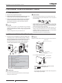
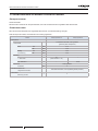
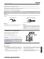
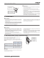
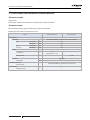
Figure 1. F-Gas Label with Protection Plastic Film Figure 2. Protection Plastic Film
Protection Plastic Film
Adhesive Surface
Peel-off Paper

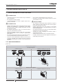
MODELS CODIFICATION
Important note: Please, check, according to the model name, which is your air con-
ditioner type, how it is abbreviated and referred to in this instruction manual. This
Installation and Operation Manual is only related to Indoor Units FSN(H)(2/3/4)(E)(i)
(k)(M) combined with Outdoor Units RAS-(4-6)H(V)NC1E.
CODIFICACIÓN DE MODELOS
Nota importante: compruebe, de acuerdo con el nombre del modelo, el tipo de sistema
de aire acondicionado del que dispone, su abreviatura y su referencia en el presente
manual de instrucciones. Este Manual de instalación y funcionamiento sólo está rela-
cionado con unidades interiores FSN(H)(2/3/4)(E)(i)(k)(M) combinadas con unidades
externas RAS-(4-6)H(V)NC1E.
MODELLCODES
Wichtiger Hinweis: Bitte stellen Sie anhand der Modellbezeichnung den Klimaanla-
gentyp und das entsprechende, in diesem Technischen Handbuch verwendete Kürzel
fest. Dieses Installations- und Betriebshandbuch bezieht sich nur auf FSN(H)(2/3/4)(E)
(i)(k)(M)-Innengeräte in Kombination mit RAS-(4-6)H(V)NC1E.
CODIFICATION DES MODÈLES
Note importante : Veuillez déterminer, d’après le nom du modèle, quel est votre
type de climatiseur et quelle est son abréviation et référence dans le présent manuel
d’instruction. Ce manuel d’installation et de fonctionnement ne concernent que les uni-
tés intérieures FSN(H)(2/3/4)(E)(i)(k)(M) combinées à des groupes extérieurs RAS-(4-
6)H(V)NC1E.
CODIFICAZIONE DEI MODELLI
Nota importante: in base al nome del modello, vericare il tipo di climatizzatore in posses-
so nonché il tipo di abbreviazione e di riferimento utilizzati in questo manuale di istruzioni.
Questo manuale di installazione e di funzionamento fa riferimento alla sola combinazione
di unità interne FSN(H)(2/3/4)(E)(i)(k)(M) e unità esterne RAS-(4-6)H(V)NC1E.
CODIFICAÇÃO DE MODELOS
Nota Importante: por favor, verique, de acordo com o nome do modelo, qual é o seu tipo
de ar condicionado, e como este é abreviado e mencionado neste manual de instruções.
Este manual de instalação e de funcionamento só está relacionado com a unidade interior
FSN(H)(2/3/4)(E)(i)(k)(M) combinada com as unidades exteriores RAS-(4-6)H(V)NC1E.
MODELKODIFICERING
Vigtig information: Kontroller modelnavnet på dit klimaanlæg for at se, hvilken type
klimaanlæg du har, hvordan det forkortes, og hvordan der henvises til det i denne ve-
jledning. Denne bruger- og monteringsvejledning gælder kun FSN(H)(2/3/4)(E)(i)(k)
(M)-indendørsenheder kombineret med RAS-(4-6)H(V)NC1E.
CODERING VAN DE MODELLEN
Belangrijke opmerking: Controleer aan de hand van de modelnaam welk type aircondi-
tioner u heeft, hoe de naam wordt afgekort en hoe ernaar wordt verwezen in deze instruc-
tie-handleiding. Deze Installatie- en bedieningshandleiding heeft alleen betrekking op
binnenunits FSN(H)(2/3/4)(E)(i)(k)(M) gecombineerd met buitenunits RAS-(4-6)H(V)
NC1E.
MODELLER
Viktigt! Kontrollera med modellnamnet vilken typ av luftkonditionering du har, hur den
förkortas och hur den anges i den här handboken. Denna handbok för installation och
användning gäller endast för inomhusenheter FSN(H)(2/3/4)(E)(i)(k)(M) kombinerade
med utomhusenheter RAS-(4-6)H(V)NC1E.
ΚΩΔΙΚΟΠΟΙΗΣΗ ΜΟΝΤΕΛΩΝ
Σημαντική σημείωση: Ελέγξτε, σύμφωνα με το όνομα μοντέλου, τον τύπο του δικού σας
κλιματιστικού και με ποια σύντμηση δηλώνεται και αναφέρεται σε αυτό το εγχειρίδιο. Αυτό
το εγχειρίδιο εγκατάστασης και λειτουργίας αφορά μόνο τις Εσωτερικές Μονάδες
FSN(H)(2/3/4)(E)(i)(k)(M) σε συνδυασμό με Εξωτερικές Μονάδες RAS-(4-6)H(V)NC1E.

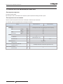
IVX Standard series
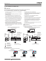
OUTDOOR UNIT · UNIDAD EXTERIOR · AUßENEINHEIT · UNITÉ EXTÉRIEURE · UNITÀ ESTERNA ·
UNIDADE EXTERIOR · UDENDRS AGGREGAT · BUITENTOESTEL · UTOMHUSENHET · ΕΞΩΤΕΡΙΚΗ ΜΟΝΑΔΑ
HEAT PUMP MODELS - MODELOS CON BOMBA DE CALOR
WÄRMEPUMPENMODELLE - MODÈLES POMPE À CHALEUR
MODELLI POMPA DI CALORE - MODELOS BOMBA DE CALOR
VARMEPUMPEMODELLER - MODELLEN MET WARMTEPOMP
MODELLER ENDAST FÖR KYLNINGSFUNKTION - ΜΟΝΤΕΛΑ ΜΕ ΑΝΤΛΙΑ ΘΕΡΜΟΤΗΤΑΣ
Single Phase - Monofásico - Einphasig - Monophasé - Monofase -
Monofásico - Enfaset - Eenfasig - En fas - Μονοφασικά
Three Phase - Trifásico - Dreiphasig - Triphasé -Trifase - Trifásico -
Trefaset - Driefasig - Trefasig - Tριφασικά
1~ 230V 50Hz 3N~ 400V 50Hz
Unit Unit
RAS-4HVNC1E RAS-4HNC1E
RAS-5HVNC1E RAS-5HNC1E
RAS-6HVNC1E RAS-6HNC1E
EN English Original version
ES Español Versión traducida
DE Deutsch Übersetzte Version
FR Français Version traduite
IT Italiano Versione tradotta
PT Português Versão traduzidal
DA Dansk Oversat version
NL Nederlands Vertaalde versie
SV Svenska Översatt version
EL Ελληνικα Μεταφρασμένη έκδοση

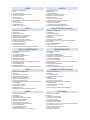
INDEX
1 GENERAL INFORMATION
2 SAFETY
3 IMPORTANT NOTICE
4 TRANSPORTATION AND HANDLING
5 BEFORE OPERATION
6 NAME OF PARTS
7 UNITS INSTALLATION
8 REFRIGERANT PIPING & REFRIGERANT CHARGE
9 DRAIN PIPING
10 ELECTRIC WIRING
11 COMMMISSIONING
12 MAIN SAFETY DEVICE
ÍNDICE
1 INFORMACIÓN GENERAL
2 SEGURIDAD
3 AVISO IMPORTANTE
4 TRANSPORTE Y MANIPULACIÓN
5 ANTES DEL FUNCIONAMIENTO
6 NOMBRE DE LAS PIEZAS
7 INSTALACIÓN DE LAS UNIDADES
8 TUBERÍA Y CARGA DE REFRIGERANTE
9 TUBERÍA DE DESAGÜE
10 CABLEADO ELÉCTRICO
11 PUESTA EN MARCHA
12 PRINCIPALES DISPOSITIVOS DE SEGURIDAD
INHALTSVERZEICHNIS
1 ALLGEMEINE INFORMATIONEN
2 SICHERHEIT
3 WICHTIGER HINWEIS
4 TRANSPORT UND BEDIENUNG
5 VOR DEM BETRIEB
6 TEILEBEZEICHNUNG
7 GERÄTEINSTALLATION
8 KÄLTEMITTELLEITUNG UND KÄLTEMITTELMENGE
9 ABFLUSSLEITUNGEN
10 KABELANSCHLUSS
11 INBETRIEBNAHME
12 GRUNDLEGENDE SICHERHEITSVORRICHTUNGEN
INDEX
1 INFORMATIONS GÉNÉRALES
2 SÉCURITÉ
3 REMARQUES IMPORTANTES
4 TRANSPORT ET MANIPULATION
5 AVANT LE FONCTIONNEMENT
6 NOMENCLATURE DES PIÈCES
7 INSTALLATION DES UNITÉS
8 TUYAUTERIE FRIGORIFIQUE ET CHARGE DU FLUIDE
FRIGORIGÈNE
9 TUYAU D'ÉVACUATION
10 CÂBLAGE ÉLECTRIQUE
11 MISE EN SERVICE
12 PRINCIPAUX DISPOSITIFS DE SÉCURITÉ
INDICE
1 INFORMAZIONI GENERALI
2 SICUREZZA
3 NOTA IMPORTANTE
4 TRASPORTO E MOVIMENTAZIONE
5 PRIMA DEL FUNZIONAMENTO
6 NOME DEI COMPONENTI
7 INSTALLAZIONE DELLE UNITÀ
8 LINEA E CARICA DI REFRIGERANTE
9 LINEA DI DRENAGGIO
10 COLLEGAMENTI ELETTRICI
11 MESSA IN ESERCIZIO
12 PRINCIPALI DISPOSITIVI DI SICUREZZA
ÍNDICE
1 INFORMAÇÃO GERAL
2 SEGURANÇA
3 NOTA IMPORTANTE
4 TRANSPORTE E MANUSEAMENTO
5 ANTES DE UTILIZAR A UNIDADE
6 NOME DAS PEÇAS
7 INSTALAÇÃO DAS UNIDADES
8 TUBAGEM E CARGA DE REFRIGERANTE
9 TUBAGEM DE DESCARGA
10 LIGAÇÕES ELÉTRICAS
11 COLOCAÇÃO EM FUNCIONAMENTO
12 DISPOSITIVO DE SEGURANÇA PRINCIPAL
INDHOLDSFORTEGNELSE
1 GENEREL INFORMATION
2 SIKKERHED
3 VIGTIG ANMÆRKNING
4 TRANSPORT OG HÅNDTERING
5 FØR DRIFT
6 NAVN PÅ DELE
7 INSTALLATION AF ENHEDER
8 KØLERØRSYSTEM OG PÅFYLDNING AF KØLEMIDDEL
9 AFLØBSRØR
10 ELECTRISKE LEDNINGER
11 IDRIFTSÆTTELSE
12 PRIMÆRE SIKKERHEDSANORDNINGER
INHOUDSOPGAVE
1 ALGEMENE INFORMATIE
2 VEILIGHEID
3 BELANGRIJKE MEDEDELING
4 TRANSPORT EN BEHANDELING
5 VOORDAT U HET SYSTEEM IN GEBRUIK NEEMT
6 NAMEN VAN ONDERDELEN
7 DE UNITS INSTALLEREN
8 KOELMIDDELLEIDINGEN & HOEVEELHEID KOELMIDDEL
9 AFVOERLEIDING
10 ELEKTRISCHE BEDRADING
11 INBEDRIJFSTELLING
12 BELANGRIJKSTE VEILIGHEIDSVOORZIENINGEN
INNEHALLSFÖRTECKNING
1 ALLMÄN INFORMATION
2 SÄKERHET
3 VIKTIG ANMÄRKNING
4 TRANSPORT OCH HANTERING
5 FÖRE DRIFT
6 DELARNAS NAMN
7 INSTALLATION AV ENHETER
8 KYLRÖR OCH PÅFYLLNING AV KYLMEDIUM
9 DRÄNERINGSRÖR
10 ELEKTRISKA ANSLUTNINGAR
11 DRIFTSÄTTNING
12 HUVUDSAKLIGA SÄKERHETSANORDNINGAR
ΕΥΡΕΤΗΡΙΟ
1 ΓΕΝΙΚΕΣ ΠΛΗΡΟΦΟΡΙΕΣ
2 ΑΦΑΛΕΙΑ
3 ΣΗΜΑΝΤΙΚΗ ΠΑΡΑΤΗΡΗΣΗ
4 ΜΕΤΑΦΟΡΑ ΚΑΙ ΧΕΙΡΙΣΜΟΣ
5 ΠΡΙΝ ΤΗ ΛΕΙΤΟΥΡΓΙΑ
6 ΟΝΟΜΑΤΑ ΕΞΑΡΤΗΜΑΤΩΝ
7 ΕΓΚΑΤΑΣΤΑΣΗ ΜΟΝΑΔΩΝ
8 ΣΩΛΗΝΩΣΕΙΣ ΨΥΚΤΙΚΟΥ & ΠΛΗΡΩΣΗ ΜΕ ΨΥΚΤΙΚΟ ΜΕΣΟ
9 ΣΩΛΗΝΩΣΕΙΣ ΑΠΟΧΕΤΕΥΣΗΣ
10 ΗΛΕΚΤΡΙΚΕΣ ΚΑΛΩΔΙΩΣΕΙΣ
11 ΕΝΑΡΞΗ ΛΕΙΤΟΥΡΓΙΑΣ
12 ΣΥΣΚΕΥΕΣ ΑΣΦΑΛΕΙΑΣ


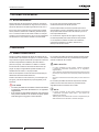
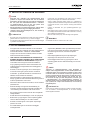
ENGLISH
1 GENERAL INFORMATION
1.1 GENERAL NOTES
No part of this publication may be reproduced, copied, led
or transmitted in any shape or form without the permission of
HITACHI Air Conditioning Products Europe, S.A.U.
Within the policy of continuous improvement of its products,
HITACHI Air Conditioning Products Europe, S.A.U. reserves
the right to make changes at any time without prior notication
and without being compelled to introducing them into products
subsequently sold.
This document may therefore have been subject to
amendments during the life of the product.
HITACHI makes every effort to offer correct, up-to-date
documentation. Despite this, printing errors cannot be controlled
by HITACHI and are not its responsibility.
As a result, some of the images or data used to illustrate this
document may not refer to specic models. No claims will be
accepted based on the data, illustrations and descriptions
included in this manual.
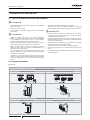
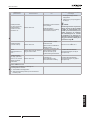
2 SAFETY
2.1 APPLIED SYMBOLS
During normal air conditioning system design work or unit
installation, greater attention must be paid in certain situations
requiring particular care in order to avoid injuries an damage to
the unit, the installation or the building or property.
Situations that jeopardise the safety of those in the surrounding
area or that put the unit itself a risk will be clearly indicated in
this manual.
To indicate these situations, a series of special symbols will be
used to clearly identify these situations.
Pay close attention to these symbols and to the messages
following them, as your safety and that of others depends on it.
! DANGER
• The text following this symbol contains information and
instructions relating directly to your safety and physical
wellbeing.
• Nottakingtheseinstructionsintoaccountcouldleadtoserious,
very serious or even fatal injuries to you and others in the
proximitiesoftheunit.
In the text following the danger symbol you can also nd
information on safe procedures during unit installation.
! CAUTION
• Thetextfollowingthissymbolcontainsinformationandinstructions
relatingdirectlytoyoursafetyandphysicalwellbeing.
• Nottakingtheseinstructionsintoaccountcouldleadtominorinjuries
toyouandothersintheproximitiesoftheunit.
• Nottakingtheseinstructionsintoaccountcouldleadtounitdamage.
In the text following the caution symbol you can also nd
information on safe procedures during unit installation.
? NOTE
• Thetextfollowingthissymbolcontainsinformationorinstructionsthat
maybeofuseorthatrequireamorethoroughexplanation.
• Instructions regarding inspections to be made on unit parts or
systemsmayalsobeincluded.
GENERAL INFORMATION
PMML0395B rev.0 - 11/2015
1

2.2 ADDITIONAL INFORMATION ABOUT SAFETY
! DANGER
• Do not pour water into the indoor or outdoor unit. These
products are equipped with electrical parts. Ifwater contacts
withelectricalcomponentsthenitwillcauseaseriouselectrical
shock.
• Do not touch or adjust safety devices inside the indoor or
outdoorunits.Ifthesedevicesaretouchedoradjusted,itmay
causeaseriousaccident.
• Donotopentheservicecoveroraccesstheindoororoutdoor
unitswithoutdisconnectingthemainpowersupply.
• IncaseofreTurnOFFthemainswitch,putoutthereatonce
andcontactyourservicecontractor.
! CAUTION
• Do notuse any sprays such asinsecticide, lacquer, hair sprayor
otherammablegaseswithinapproximatelyone(1)meterfromthe
system.
• If circuit breaker or fuse is often activated, stop the system and
contactyourservicecontractor.
• Do not make service or inspections tasks by yourself. This works
mustbeperformedbyqualiedserviceperson.
• Donotputanystrangematerial(sticks,etc...)intotheairinletand
outlet.Theseunitshavehighspeedrotatingfansanditisdangerous
thatanyobjecttouchesthem.
• Refrigerant leakage can cause difculty with breathing due to
insufcientair.
• This appliance must be used only by adult and capable people,
having receivedthe technicalinformation or instructions to handle
properlyandsafelythisappliance.
• Childrenshouldbesupervisedtoensurethattheydonotplaywith
theappliance.
? NOTE
Itisrecommendedtoventilatetheroomevery3or4hours.
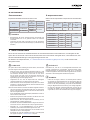
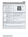
3 IMPORTANT NOTICE
• The supplementary information about the purchased
products is supplied in a CD-ROM, which can be found
bundled with the outdoor unit. In case that the CD-ROM is
missing or it is not readable, please contact your Hitachi
dealer or distributor.
• PLEASE READ THE MANUAL AND THE FILES ON
THE CD-ROM CAREFULLY BEFORE STARTING WORK
ON THE INSTALLATION OF THE AIR CONDITIONING
SYSTEM. Failure to observe the instructions for installation,
use and operation described in this documentation may
result in operating failure including potentially serious faults,
or even the destruction of the air conditioning system
• Verify, in accordance with the manuals which appear in the
outdoor and indoor units, that all the information required for
the correct installation of the system is included. If this is not
the case, contact your distributor.
• HITACHI pursues a policy of continuing improvement
in design and performance of products. The right is therefore
reserved to vary specications without notice.
• HITACHI cannot anticipate every possible circumstance that
might involve a potential hazard.
• This air conditioner has been designed for standard air
conditioning for human beings. For use in other applications,
please contact your HITACHI dealer or service contractor.
• No part of this manual may be reproduced without written
permission.
• If you have any questions, contact your service contractor of
HITACHI.
• This manual gives a common description and information
for this air conditioner which you operate as well as for other
models.
• Check and make sure that the explanations of each part of
this manual correspond to your air conditioner model.
• Refer to the models codication to conrm the main
characteristics of your system.
• Signal words (NOTE, DANGER and CAUTION) are used
to identify levels of hazard seriousness. Denitions for
identifying hazard levels are provided below with their
respective signal words.
• These operations modes are controlled by the remote
control switch.
• This manual should be considered as a permanent part of
the air conditioner. This manual gives a common description
and information for this air conditioner which you operate as
well as for other models.
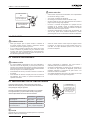
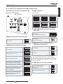
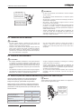
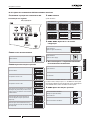
! DANGER
PressureVesselandSafetyDevice:Thisairconditionerisequipped
with a high pressure vessel under PED (Pressure Equipment
Directive). The pressure vessel has been designed and tested
before shipment according to PED. Also, in order to prevent the
systemfromanabnormalpressure,ahighpressureswitch,which
needs no eld adjustment, is utilized in the refrigeration system.
Therefore,thisairconditionerisprotectedfromabnormalpressures.
However,ifabnormallyhighpressureisappliedtotherefrigeration
cycleincludingthehighpressurevessel(s),itwillresultinserious
injuryordeathduetoexplosionofthepressurevessel.Donotapply
a pressure higher than the following pressure to the system, by
modifyingorchangingthehighpressureswitch.
! CAUTION
This unit is designed for commercial and light industrial application.
If installed in house hold appliance, it could cause electromagnetic
interference.
IMPORTANT NOTICE
PMML0395B rev.0 - 11/2015
2

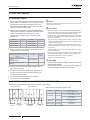
ENGLISH
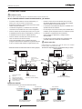
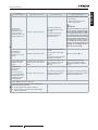
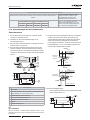
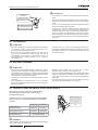
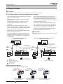
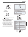
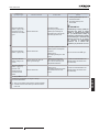
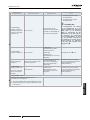
Start-up and Operation: Checktoensurethatallthestopvalvesarefullyopenedandnoobstacleexistsattheinlet/outletsides
beforestart-upandduringtheoperation.
Maintenance:Periodicallycheckthehighpressuresidepressure.Ifthepressureishigherthanthemaximumallowablepressure,
stopthesystemandcleantheheatexchangerorremovethecause.
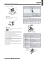
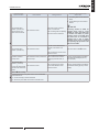
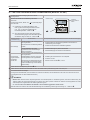
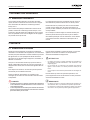
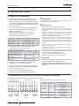
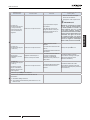
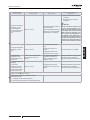
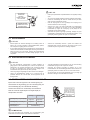
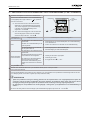
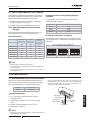
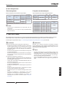
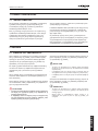
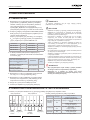
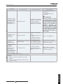
Maximum Allowable Pressure and High Pressure Cut-out Value:
Refrigerant Maximum Allowable Pressure (MPa) High Pressure Switch Cut-out Value (MPa)
R410A 4.15 4.00 ~ 4.10
? NOTE
ThelabelforthevesselunderPEDareattachedonthehighpressurevessel.Thepressurevesselcapacityandvesselcategoryareindicatedonthe
vessel.
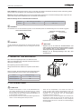
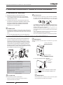
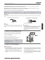
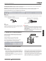
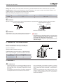
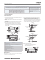
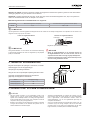
Location of High Pressure Switch
Compressor
? NOTE
Thehighpressureswitchisindicatedontheelectricalwiringdiagramin
theoutdoorunitasPSHconnectedtoprintedcircuitboard(PCB1)inthe
outdoorunit.
Structure of High Pressure Switch
Contact Point Pressure Detected
Connected to the electrical wire
! DANGER
• Donot changethehigh-pressureswitchlocallyorchange the
highpressurecut-outsetvaluelocally.Ifchanged,itwillcause
seriousinjuryordeathduetoexplosion.
• Donotattempttoturnservicevalverodbeyonditsstop.
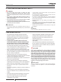
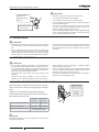
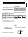
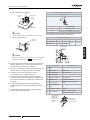
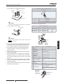
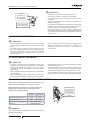
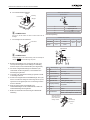
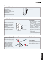
4 TRANSPORTATION AND HANDLING
When hanging the unit, ensure a balance of the unit, check
safety and lift it up smoothly
Do not remove any packing materials.
Hang the unit under packing condition with two ropes.
For safety reasons ensure that the outdoor unit is lifted smoothly
and does not lean
Model Gross Weight (kg)
RAS-4H(V)NC1E 92
RAS(5-6)H(V)NC1E 102
5 BEFORE OPERATION
! CAUTION
• Supply electrical power to the system for approximately 12 hours
before start-up or a long shutdown. Do not start the system
immediatelyafterpowersupply,itmaycausea compressor failure
becausethecompressorisnotheatedwell.
• Whenthesystemisstartedafterashutdownlongerthatapproximately
3months,itisrecommended to check thesystembyyourservice
contractor.
• TurnOFFthemainswitchwhenthesystemistobestoppedforalong
periodoftime:IfthemainswitchisnotturnedOFF,electricitywillbe
used,becausetheoilheaterisalwaysenergisedduringcompressor
stopping.
• Makesure thattheoutdoorunitisnot coveredwithsnoworice.If
covered,removeitbyusing hot water (approximately50°C).Ifthe
watertemperatureishigherthat50°C,itwillcausedamagetoplastic
parts.
TRANSPORTATION AND HANDLING
PMML0395B rev.0 - 11/2015
3

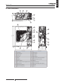
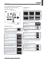
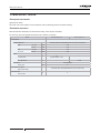
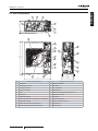
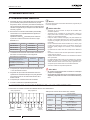
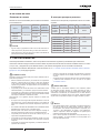
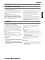
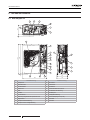
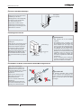
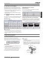
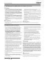
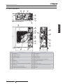
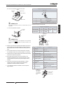
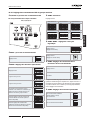
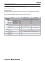
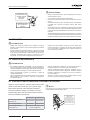
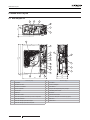
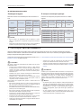
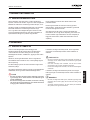
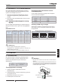
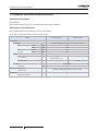
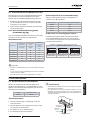
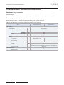
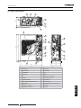
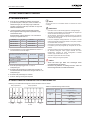
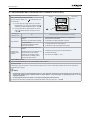
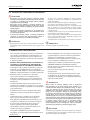
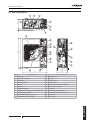
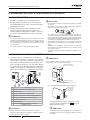
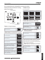
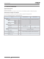
6 NAME OF PARTS
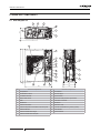
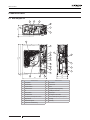
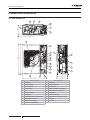
6.1 RAS-4H(V)NC1E
410
32
1108
1140
37048
440950
3
1
24
5
5
6
7
8
9
10
11
12
13
14
15
16
17
12
1819
19
20
21
21
Nº Part Name Nº Part Name
1 Compressor 12 Accumulator
2 Heat exchanger 13 Check Joint
3 Propeller fan 14 Electrical box
4 Fan motor 15 High pressure switch for protection
5 Strainer 16 Pressure switch for control
6 Distributor 17 Silencer
7 Reversing valve 18 Crankcase heater
8 Micro-computer control expansion valve 19 Vibration absorbing rubber (4 pcs.)
9 Solenoid valve 20 Air outlet
10 Stop valve for gas line 21 Air inlet
11 Stop valve for liquid line
NAME OF PARTS
PMML0395B rev.0 - 11/2015
4

ENGLISH
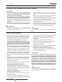
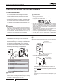
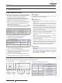
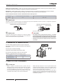
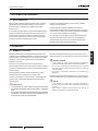
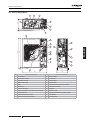
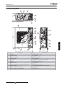
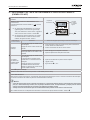
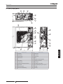
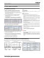
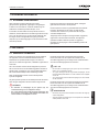
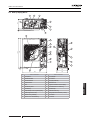
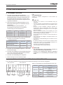
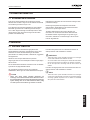
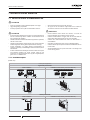
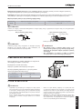
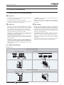
6.2 RAS-(5-6)H(V)NC1E
410
3
4
37048
22
22 2
7
9
1108
1140
32
950
21
15
14
8
5
13
440
6
1
10
11
5
18
12
17
16
19
20
Nº Part Name Nº Part Name
1 Compressor 12 Check valve
2 Heat exchanger 13 Accumulator
3 Propeller fan 14 Check joint
4 Fan motor 15 Electrical box
5 Strainer 16 High pressure switch for protection
6 Distributor 17 Pressure switch for control
7 Reversing Valve 18 Silencer
8 Micro-computer control expansion valve 19 Crankcase heater
9 Solenoid valve 20 Vibration absorbing rubber (4pcs.)
10 Stop valve for gas line 21 Air outlet
11 Stop valve for liquid line 22 Air inlet
NAME OF PARTS
PMML0395B rev.0 - 11/2015
5

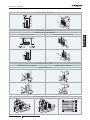
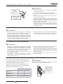
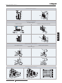
7 UNITS INSTALLATION
7.1 OUTDOOR UNITS INSTALLATION
! CAUTION
• Transporttheproductsasclosetotheinstallationlocationaspractical
beforeunpacking.
• Donotputanymaterialontheproducts.
• Applyfourliftingwiresontotheoutdoor,whenliftingitbycrane
! CAUTION
• Install the outdoor unit with sufcient clearance around it for
operation and maintenance as shown in the next gures.
Installtheoutdoorunitwheregoodventilationisavailable
• Donotinstalltheoutdoorunitwhereisahighlevelofoilmist,saltyair
orsulphurousatmosphere.
• Installtheoutdoorunitasfaraspractical(beingatleast3 meters)
fromelectromagneticwaveradiator(suchasmedicalequipment).
• Forcleaning,usenoninammableandnontoxiccleaningliquid.Use
ofinammableagentmaycauseexplosionorre.
• Workwithsufcientventilation,forworkinginanenclosedspacemay
causeoxygendeciency.Toxicgasmaybeproducedwhencleaning
agentisheatedtohightemperatureby,e.g.,beingexposedtore.
• Cleaningliquidshallbecollectedaftercleaning.
• Payattentionnottoclampcableswhenattachingtheservicecoverto
avoidelectricshockorre.
! CAUTION
• Keepclearancebetweentheunitsofmorethan100mm,andavoid
obstaclesthatmayhamperairintake,wheninstallingmorethanone
unitstogether.
• Installtheoutdoorunitintheshadeornotexposedtodirectsunshine
ordirectradiationfromhightemperatureheatsource.
• Donot installthe Outdoor Unitin aspace where a seasonal wind
directlyblowstotheOutdoorfan.
• Check to ensure that the foundation is at, level and sufciently
strong.
• Installtheunitinarestrictedareanotaccessiblebythegeneralpublic
• Aluminiumnshaveverysharpedges.Payattention to the ns to
avoidinjury.
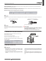
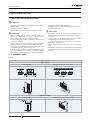
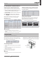
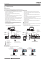
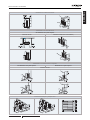
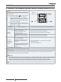
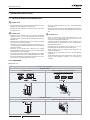
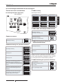
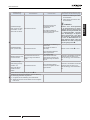
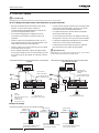
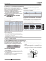
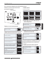
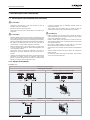
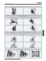
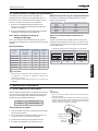
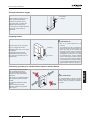
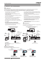
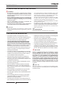
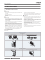
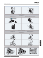
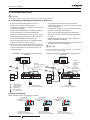
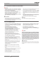
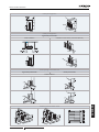
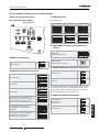
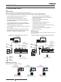
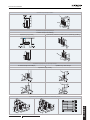
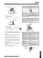
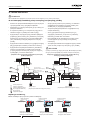
7.1.1 Installation space
(Unit: mm)
Blocked in Inlet Side
Upper Side Open
Single Installation Multiple Installation (Two units or more)
*
*
Front Side
Front
Side
Front Side
Front Side
Upper Side Blocked
Single Installation Multiple Installation (Two units or more)
UNITS INSTALLATION
PMML0395B rev.0 - 11/2015
6

ENGLISH
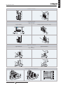
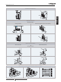
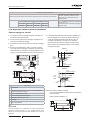
Blocked in Inlet Side
Outlet Side Blocked
Upper Side Open
Single Installation Multiple Installation (Two units or more)
Right and Left Blocked
Upper Side Open Upper Side Blocked
Single Installation
Multi-Row and Multiple Installations
UNITS INSTALLATION
PMML0395B rev.0 - 11/2015
7

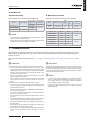
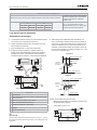
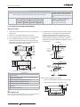
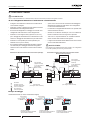
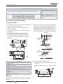
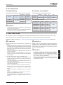
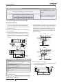
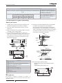
Multi-Row and Multiple Installations
Mount the airow guide and provide sufcient space on both right and left sides
When using airow guide (AG-335A,
optional), check that the discharged air is not
short-circuited to the air inlet side
A B
0 < L ≤ 1/2H 1/2H < L≤ H 0 < L ≤ 1/2H 1/2H < L≤ H
Min. 600 Min. 1400 Min. 300 Min. 350
When L > H use a base for outdoor unit to
make L ≤ H.
Close the base not to allow the outlet air
bypassed.
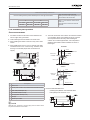
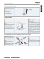
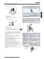
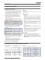
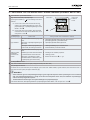
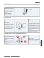
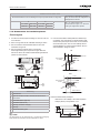
7.1.2 Installation place provision
Concrete Foundation
1 Foundation could be on at and is recommended be 100-
300 mm higher than ground level.
2 Install a drainage around foundation for smooth drain
3 When installing the outdoor unit x the unit by anchor bolts
of M10.
4 When installing the unit on a roof or a veranda, drain water
sometimes turns to ice on a cold morning. Therefore, avoid
draining in an area that people often use because it is
slippery.
* Space for downward piping space
Nº Description
Outdoor Unit
Cut this portion of bolt If not, it’s difcult to remove Service Cover
Mortar Hole (Ø100xDepth 150)
Anchor Bolt M10 (Ø12.5 Hole)
Drainage (Wide 100xDepth 150)
Drainage
Vibration-proof rubber
? NOTE
Whenthemark*dimensionissecured,pipingworkfrombottomsideis
easywithoutinterferenceoffoundation.
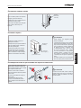
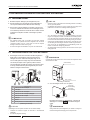
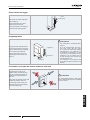
5 The whole of the base of the outdoor unit should be installed
on a foundation. When using vibration-proof mat, it should
also be positioned the same way. When installing the
outdoor unit on a eld supplied frame, use metal plates to
adjust the frame width for stable installation as shown in
below gure.
70 mm
Base width of outdoor unit
Outdoor unit
is unstable
Frame
60mm
Frame width (Field supplied)
INCORRECT
CORRECT
Outdoor unit
is stable
70 mm
Base width of outdoor unit
Frame
100mm or more
Metal plate
Recommended Metal Plate Size
- (Field-Supplied) Material: Hot-Rolled Mild Steel
- Plate (SPHC) Plate Thickness: 4.5 T
UNITS INSTALLATION
PMML0395B rev.0 - 11/2015
8

ENGLISH
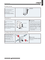
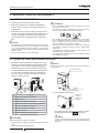
Fix Unit to the wall
Fix the Unit onto the wall as the gure
indicates. (eld supplied stay)
Ensure the foundation so that avoid the
deforming and noise.
In case of prevention from vibration
transfer to the building, use rubber Mat.
Rubber Material
(Field Supplied)
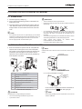
Suspended unit
Suspend the unit as the drawing
indicates.
Ensure that wall can resist the Outdoor
unit weight indicated in specication label
plate.
It is recommended to select each foot
support to bear the full weight of the unit
(in order to consider stress fatigue applied
when unit is working too).
Wall bracket (*)
Anchor Bolts (*)
(*) Field supplied
! CAUTION
• Payattentiontothefollowingforinstallation:
• Installation shall ensure that outdoor unit
will not incline, vibrate,make noise or fall
downbyablastofwindorinanearthquake.
Calculate quake-resistance strength to
ensure that installation is strong enough
againstfalling.Fixtheunitwithwires(eld
supplied) when installing in a location
without walls or windbreak and likely
exposedtoablastofwind.
• Touseavibration-proofmat,xfourplaces
tothefrontandback.
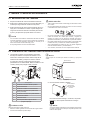
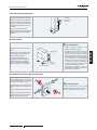
Installing location where the unit will be exposed to strong wind
Follow the instructions below to install
on the rooftop or a location without
surrounding buildings, where strong wind
is expected against the product.
Choose a location where the outlet
or inlet side of the product will not be
exposed to strong wind.
When the outlet is exposed to strong
wind:
Direct strong wind may cause lack of air
ow and adversely affect to the operation.
! CAUTION
Excessivestrongwindagainsttheoutdoorunit
outletmaycauseinverserotationanddamage
thefanandmotor.
UNITS INSTALLATION
PMML0395B rev.0 - 11/2015
9

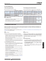
8 REFRIGERANT PIPING & REFRIGERANT CHARGE
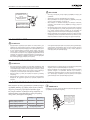
8.1 PIPING MATERIALS
1 Prepare locally-supplied copper pipes.
2 Select the piping size with the correct thickness and correct
material which can have sufcient pressure strength.
3 Select clean copper pipes. Make sure there is no dust and
moisture inside. Blow the inside of the pipes with oxygen
free nitrogen to remove any dust and foreign materials
before connecting pipes.
? NOTE
• A system with nomoisture or oilcontamination will give maximum
performance and lifecycle compared to that of a poorly prepared
system.Takeparticularcaretoensureallcopperpipingiscleanand
dryinternally.
• Thereisnorefrigerantinthecycleoftheindoorunit.
! CAUTION
• Captheendofthepipewhenpipeistobeinsertedthroughahole.
• Donotputpipesonthegrounddirectlywithoutacaporvinyltapeat
theendofthepipe
• Ifpipinginstallationisnotcompleteduntilnextdayoroveralonger
period of time, braze off the ends of the piping and charge with
oxygenfreenitrogenthroughaSchradervalvetypeaccessttingto
preventmoistureandparticlecontamination.
• Do not use insulation material that contains NH3 because it can
damagecooperpipematerialandcanbeasourceoffutureleakage.
• Completely insulate both refrigerant gas piping and liquid piping
betweentheindoorunit(s)andtheoutdoorunit.
• Ifnotinsulated,dewwillocuronthepipingsurface
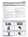
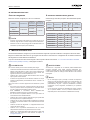
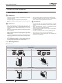
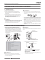
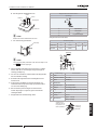
8.2 PIPING CONNECTION FOR OUTDOOR UNIT
1 The pipes can be connected from 4 directions. Make holes
in the piping cover or cabinet for taking out pipes. Take the
piping cover away from the unit, and make holes by cutting
along the guideline at the rear of the cover or punching
with a driver. Remove the burr with a cutter, and place a
insulation (eld supplied) to protect cables and pipes.
Nº Description
Rear side piping work
Pipe Cover
Right side piping work
Bottom side piping work (Knock out hole)
Front side piping work
Piping work
Stop Valve
Removing Direction for Service Cover
(picture as example)
! CAUTION
Notestoopen/closetheservicecover:
• Removethescrewsfollowingtheinstructionstotheabovegure.
• Slowlypressdownthecover.
? NOTE
Holdthecoverwithahandtoremovescrewsasthecovermayfalldown.
Service cover
Clasp (3 places)
(pictureasexample)
a. For the front and side piping
Front piping hole
Side piping hole
To use racking or conduit tubes, check the size and
remove part following the slit.
? NOTE
Placeinsulation(eldsupplied)toprotectcablesandpipesfrom
beingdamagedbyplateedges.
REFRIGERANT PIPING & REFRIGERANT CHARGE
PMML0395B rev.0 - 11/2015
10
La page est en cours de chargement...
La page est en cours de chargement...
La page est en cours de chargement...
La page est en cours de chargement...
La page est en cours de chargement...
La page est en cours de chargement...
La page est en cours de chargement...
La page est en cours de chargement...
La page est en cours de chargement...
La page est en cours de chargement...
La page est en cours de chargement...
La page est en cours de chargement...
La page est en cours de chargement...
La page est en cours de chargement...
La page est en cours de chargement...
La page est en cours de chargement...
La page est en cours de chargement...
La page est en cours de chargement...
La page est en cours de chargement...
La page est en cours de chargement...
La page est en cours de chargement...
La page est en cours de chargement...
La page est en cours de chargement...
La page est en cours de chargement...
La page est en cours de chargement...
La page est en cours de chargement...
La page est en cours de chargement...
La page est en cours de chargement...
La page est en cours de chargement...
La page est en cours de chargement...
La page est en cours de chargement...
La page est en cours de chargement...
La page est en cours de chargement...
La page est en cours de chargement...
La page est en cours de chargement...
La page est en cours de chargement...
La page est en cours de chargement...
La page est en cours de chargement...
La page est en cours de chargement...
La page est en cours de chargement...
La page est en cours de chargement...
La page est en cours de chargement...
La page est en cours de chargement...
La page est en cours de chargement...
La page est en cours de chargement...
La page est en cours de chargement...
La page est en cours de chargement...
La page est en cours de chargement...
La page est en cours de chargement...
La page est en cours de chargement...
La page est en cours de chargement...
La page est en cours de chargement...
La page est en cours de chargement...
La page est en cours de chargement...
La page est en cours de chargement...
La page est en cours de chargement...
La page est en cours de chargement...
La page est en cours de chargement...
La page est en cours de chargement...
La page est en cours de chargement...
La page est en cours de chargement...
La page est en cours de chargement...
La page est en cours de chargement...
La page est en cours de chargement...
La page est en cours de chargement...
La page est en cours de chargement...
La page est en cours de chargement...
La page est en cours de chargement...
La page est en cours de chargement...
La page est en cours de chargement...
La page est en cours de chargement...
La page est en cours de chargement...
La page est en cours de chargement...
La page est en cours de chargement...
La page est en cours de chargement...
La page est en cours de chargement...
La page est en cours de chargement...
La page est en cours de chargement...
La page est en cours de chargement...
La page est en cours de chargement...
La page est en cours de chargement...
La page est en cours de chargement...
La page est en cours de chargement...
La page est en cours de chargement...
La page est en cours de chargement...
La page est en cours de chargement...
La page est en cours de chargement...
La page est en cours de chargement...
La page est en cours de chargement...
La page est en cours de chargement...
La page est en cours de chargement...
La page est en cours de chargement...
La page est en cours de chargement...
La page est en cours de chargement...
La page est en cours de chargement...
La page est en cours de chargement...
La page est en cours de chargement...
La page est en cours de chargement...
La page est en cours de chargement...
La page est en cours de chargement...
La page est en cours de chargement...
La page est en cours de chargement...
La page est en cours de chargement...
La page est en cours de chargement...
La page est en cours de chargement...
La page est en cours de chargement...
La page est en cours de chargement...
La page est en cours de chargement...
La page est en cours de chargement...
La page est en cours de chargement...
La page est en cours de chargement...
La page est en cours de chargement...
La page est en cours de chargement...
La page est en cours de chargement...
La page est en cours de chargement...
La page est en cours de chargement...
La page est en cours de chargement...
La page est en cours de chargement...
La page est en cours de chargement...
La page est en cours de chargement...
La page est en cours de chargement...
La page est en cours de chargement...
La page est en cours de chargement...
La page est en cours de chargement...
La page est en cours de chargement...
La page est en cours de chargement...
La page est en cours de chargement...
La page est en cours de chargement...
La page est en cours de chargement...
La page est en cours de chargement...
La page est en cours de chargement...
La page est en cours de chargement...
La page est en cours de chargement...
La page est en cours de chargement...
La page est en cours de chargement...
La page est en cours de chargement...
La page est en cours de chargement...
La page est en cours de chargement...
La page est en cours de chargement...
La page est en cours de chargement...
La page est en cours de chargement...
La page est en cours de chargement...
La page est en cours de chargement...
La page est en cours de chargement...
La page est en cours de chargement...
La page est en cours de chargement...
La page est en cours de chargement...
La page est en cours de chargement...
La page est en cours de chargement...
La page est en cours de chargement...
La page est en cours de chargement...
La page est en cours de chargement...
La page est en cours de chargement...
La page est en cours de chargement...
La page est en cours de chargement...
La page est en cours de chargement...
La page est en cours de chargement...
La page est en cours de chargement...
La page est en cours de chargement...
La page est en cours de chargement...
La page est en cours de chargement...
La page est en cours de chargement...
La page est en cours de chargement...
La page est en cours de chargement...
La page est en cours de chargement...
La page est en cours de chargement...
La page est en cours de chargement...
La page est en cours de chargement...
La page est en cours de chargement...
La page est en cours de chargement...
La page est en cours de chargement...
La page est en cours de chargement...
La page est en cours de chargement...
La page est en cours de chargement...
La page est en cours de chargement...
La page est en cours de chargement...
La page est en cours de chargement...
La page est en cours de chargement...
La page est en cours de chargement...
La page est en cours de chargement...
La page est en cours de chargement...
La page est en cours de chargement...
La page est en cours de chargement...
La page est en cours de chargement...
La page est en cours de chargement...
La page est en cours de chargement...
La page est en cours de chargement...
La page est en cours de chargement...
La page est en cours de chargement...
La page est en cours de chargement...
La page est en cours de chargement...
La page est en cours de chargement...
-
 1
1
-
 2
2
-
 3
3
-
 4
4
-
 5
5
-
 6
6
-
 7
7
-
 8
8
-
 9
9
-
 10
10
-
 11
11
-
 12
12
-
 13
13
-
 14
14
-
 15
15
-
 16
16
-
 17
17
-
 18
18
-
 19
19
-
 20
20
-
 21
21
-
 22
22
-
 23
23
-
 24
24
-
 25
25
-
 26
26
-
 27
27
-
 28
28
-
 29
29
-
 30
30
-
 31
31
-
 32
32
-
 33
33
-
 34
34
-
 35
35
-
 36
36
-
 37
37
-
 38
38
-
 39
39
-
 40
40
-
 41
41
-
 42
42
-
 43
43
-
 44
44
-
 45
45
-
 46
46
-
 47
47
-
 48
48
-
 49
49
-
 50
50
-
 51
51
-
 52
52
-
 53
53
-
 54
54
-
 55
55
-
 56
56
-
 57
57
-
 58
58
-
 59
59
-
 60
60
-
 61
61
-
 62
62
-
 63
63
-
 64
64
-
 65
65
-
 66
66
-
 67
67
-
 68
68
-
 69
69
-
 70
70
-
 71
71
-
 72
72
-
 73
73
-
 74
74
-
 75
75
-
 76
76
-
 77
77
-
 78
78
-
 79
79
-
 80
80
-
 81
81
-
 82
82
-
 83
83
-
 84
84
-
 85
85
-
 86
86
-
 87
87
-
 88
88
-
 89
89
-
 90
90
-
 91
91
-
 92
92
-
 93
93
-
 94
94
-
 95
95
-
 96
96
-
 97
97
-
 98
98
-
 99
99
-
 100
100
-
 101
101
-
 102
102
-
 103
103
-
 104
104
-
 105
105
-
 106
106
-
 107
107
-
 108
108
-
 109
109
-
 110
110
-
 111
111
-
 112
112
-
 113
113
-
 114
114
-
 115
115
-
 116
116
-
 117
117
-
 118
118
-
 119
119
-
 120
120
-
 121
121
-
 122
122
-
 123
123
-
 124
124
-
 125
125
-
 126
126
-
 127
127
-
 128
128
-
 129
129
-
 130
130
-
 131
131
-
 132
132
-
 133
133
-
 134
134
-
 135
135
-
 136
136
-
 137
137
-
 138
138
-
 139
139
-
 140
140
-
 141
141
-
 142
142
-
 143
143
-
 144
144
-
 145
145
-
 146
146
-
 147
147
-
 148
148
-
 149
149
-
 150
150
-
 151
151
-
 152
152
-
 153
153
-
 154
154
-
 155
155
-
 156
156
-
 157
157
-
 158
158
-
 159
159
-
 160
160
-
 161
161
-
 162
162
-
 163
163
-
 164
164
-
 165
165
-
 166
166
-
 167
167
-
 168
168
-
 169
169
-
 170
170
-
 171
171
-
 172
172
-
 173
173
-
 174
174
-
 175
175
-
 176
176
-
 177
177
-
 178
178
-
 179
179
-
 180
180
-
 181
181
-
 182
182
-
 183
183
-
 184
184
-
 185
185
-
 186
186
-
 187
187
-
 188
188
-
 189
189
-
 190
190
-
 191
191
-
 192
192
-
 193
193
-
 194
194
-
 195
195
-
 196
196
-
 197
197
-
 198
198
-
 199
199
-
 200
200
-
 201
201
-
 202
202
-
 203
203
-
 204
204
-
 205
205
-
 206
206
-
 207
207
-
 208
208
-
 209
209
-
 210
210
-
 211
211
-
 212
212


Hitachi RAS-(4-6)H(V)NC1E Manuel utilisateur
- Catégorie
- Climatiseurs split-system
- Taper
- Manuel utilisateur
- Ce manuel convient également à
dans d''autres langues
- italiano: Hitachi RAS-(4-6)H(V)NC1E Manuale utente
- English: Hitachi RAS-(4-6)H(V)NC1E User manual
- español: Hitachi RAS-(4-6)H(V)NC1E Manual de usuario
- Deutsch: Hitachi RAS-(4-6)H(V)NC1E Benutzerhandbuch
- Nederlands: Hitachi RAS-(4-6)H(V)NC1E Handleiding
- português: Hitachi RAS-(4-6)H(V)NC1E Manual do usuário
- dansk: Hitachi RAS-(4-6)H(V)NC1E Brugermanual
- svenska: Hitachi RAS-(4-6)H(V)NC1E Användarmanual
Documents connexes
-
Hitachi RAS-12FSNM Manuel utilisateur
-
Hitachi UTOPIA IVX PREMIUM Series Mode d'emploi
-
-
-
-
-
-
-
-
Autres documents
-
Clatronic CL 3671 Manuel utilisateur
-
 Olimpia Splendid Sherpa AQUADUE S2 Manuale d'installazione
-
Airwell DUO 18 Manuel utilisateur
-
-
Dometic B3200 Mode d'emploi
-
Panasonic U10MES2E8 Mode d'emploi
-
QLIMA S(C) 33xx Guide d'installation
-
Fujitsu ROG72LRLA Guide d'installation
-
 Beninca SA02E Le manuel du propriétaire
-
Aereco VBP Guide d'installation

