ESAB Spool Gun Manuel utilisateur
- Catégorie
- Système de soudage
- Taper
- Manuel utilisateur

Issue Date: January, 2012
Manual No: 89210002Revision: B
ART# A-11080
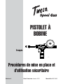
Safety and Operating
Instructions
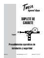
SPOOL GUN
English
Français
Español

WE APPRECIATE YOUR BUSINESS!
Congratulations on your new Tweco
®
product. We are proud to have you
as our customer and will strive to provide you with the best service and
reliability in the industry. This product is backed by our extensive warranty
and world-wide service network. To locate your nearest distributor or service
agency call 800-426-1888, or visit us on the web at www.tweco.com.
This Manual has been designed to instruct you on the correct installation
and use of your Tweco
®
product. Your satisfaction with this product and its
safe operation is our ultimate concern. Therefore, please take the time to
read the entire manual, especially the Safety Precautions. They will help you
to avoid potential hazards that may exist when working with this product.
YOU ARE IN GOOD COMPANY!
The Brand of Choice for Contractors and Fabricators
Worldwide.
Tweco
®
is a Global Brand of Arc Welding Products for Thermadyne
Industries Inc. We manufacture and supply to major welding industry
sectors worldwide including; Manufacturing, Construction, Mining,
Automotive, Aerospace, Engineering, Rural and DIY/Hobbyist.
We distinguish ourselves from our competition through market-leading,
dependable products that have stood the test of time. We pride ourselves
on technical innovation, competitive prices, excellent delivery, superior
customer service and technical support, together with excellence in sales
and marketing expertise.
Above all, we are committed to develop technologically advanced products
to achieve a safer working environment within the welding industry.

i
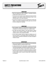
WARNINGS
Read and understand this entire Manual and your employer’s safety practices before
installing, operating, or servicing the equipment. While the information contained in
this Manual represents the Manufacturer’s judgment, the Manufacturer assumes no
liability for its use.
Tweco Spool Gun; SG200TA-25-3545
Set-up and Safe Operating Procedures
Instruction Guide Number 89210002
Published by:
Thermadyne
®
Industries, Inc.
2800 Airport Rd.
Denton, TX. 76208
(940) 566-2000
www.thermadyne.com
U.S. Customer Care: (800) 426-1888
International Customer Care: (940) 381-1212
Copyright © 2011, 2012 Thermadyne Industries, Inc. All rights reserved.
Reproduction of this work, in whole or in part, without written permission of the publisher is prohibited.
The publisher does not assume and hereby disclaims any liability to any party for any loss or damage caused by any
error or omission in this Manual, whether such error results from negligence, accident, or any other cause.
Publication Date: January 2012
Record the following information for Warranty purposes:
Where Purchased:
Purchase Date:
Equipment Serial #:

ii
Table of Contents
SECTION 1: SAFETY PRECAUTIONS ....................................................................... 1-1
SECTION 2: MODEL SPECIFICATIONS .................................................................... 2-4
SECTION 3: INSTALLATION AND OPERATION ........................................................ 3-5
3.01 Connecting the spool gun ................................................. 3-5
3.02 Adjusting wire feed pressure and speed ........................... 3-6
3.03 Installing the wire spool ................................................... 3-6
3.04 Wire feed speed calibration .............................................. 3-8
SECTION 4: CARE AND MAINTENANCE ................................................................ 4-13
4.01 Changing the contact tip ................................................. 4-13
4.02 Changing the wire conduit ..............................................4-14
4.03 Changing the drive rolls .................................................4-15
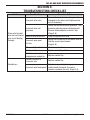
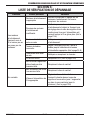
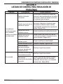
SECTION 5: TROUBLESHOOTING CHECK LIST ...................................................... 5-17
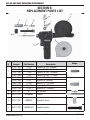
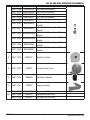
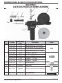
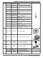
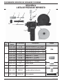
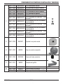
SECTION 6: REPLACEMENT PARTS LIST .............................................................. 6-18
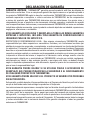
STATEMENT OF WARRANTY ................................................................................. 6-20

SET-UP AND SAFE OPERATING PROCEDURES
1-1
89210002
Safety Precautions
SECTION 1:
SAFETY PRECAUTIONS
WARNING
SERIOUS INJURY OR DEATH may result if welding and cutting equipment is not properly
installed, used, and maintained. Misuse of this equipment and other unsafe practices
can be hazardous. The operator, supervisor, and helper must read and understand the
following safety warnings and instructions before installing or using any welding or cutting
equipment, and be aware of the dangers of the welding or cutting process. Training
and proper supervision are important for a safe work place. Keep these instructions for
future use. Additional recommended safety and operating information is referenced in
each section.
ELECTRIC SHOCK CAN CAUSE INJURY OR DEATH
Install and maintain equipment in accordance with the National Electrical Code (NFPA
70) and local codes. Do not service or repair equipment with power on. Do not operate
equipment with protective insulators or covers removed. Service or repair to equipment
must be done by qualifi ed and/or trained personnel only.
Do not contact electrically live parts. Always wear dry welding gloves that are in good condition.
Aluminized, protective clothing can become part of the electrical path. Keep oxygen cylinders, chains,
wires, ropes, cranes, and hoists away from any part of the electrical path. All ground connections must
be checked periodically to determine if they are mechanically strong, and electrically adequate for the
required current. When engaged in AC welding/cutting under wet conditions or where perspiration is a
factor, the use of automatic controls for reducing the no load voltage is recommended to reduce shock
hazards. Accidental contact must be prevented when using open circuit voltage exceeding 80 volts AC,
or 100 volts DC by adequate insulation or other means. When welding is to be suspended for any length
of time, such as during lunch or overnight, all electrode holders and electrodes should be removed from
the electrode holder and the power supply should be turned OFF to prevent accidental contact. Keep
MIG-Guns, electrode holders, TIG torches, Plasma torches, and electrodes away from moisture and
water. See safety and operating references 1, 2, and 8.
SMOKE, FUMES, AND GASES CAN BE DANGEROUS TO YOUR HEALTH
Ventilation must be adequate to remove smoke, fumes, and gases during operation to
protect operators and others in the area. Vapors of chlorinated solvents can form the
toxic gas “Phosgene” when exposed to ultraviolet radiation from an electric arc. All
solvents, degreasers, and potential sources of these vapors must be removed from the
operating area. Use air-supplied respirators if ventilation is not adequate to remove all
fumes and gases. Oxygen supports, and vigorously accelerates fi re and should never be used for
ventilation. See safety and operating references 1, 2, 3, and 4.

1-2
SET-UP AND SAFE OPERATING PROCEDURES
89210002Safety Precautions
ARC RAYS, HOT SLAG, AND SPARKS CAN INJURE EYES AND BURN SKIN
Welding and cutting processes produce extreme localized heat and strong ultraviolet
rays. Never attempt to weld/cut without a federally compliant welding helmet with the
proper lens. A number 12 to 14 shade fi lter lens provides the best protection against
arc radiation. When in a confi ned area, prevent the refl ected arc rays from entering
around the helmet. Approved shielding curtains and appropriate goggles should be used
to provide protection to others in the surrounding area. Skin should be protected from arc rays, heat,
and molten metal. Always wear protective gloves and clothing. All pockets should be closed and cuffs
sewn shut. Leather aprons, sleeves, leggings, etc. should be worn for out-of-position welding and cutting,
or for heavy operations using large electrodes. Hightop work shoes provide adequate protection from
foot burns. For added protection, use leather spats. Flammable hair preparations should not be used
when welding/cutting. Wear ear plugs to protect ears from sparks. Where work permits, the operator
should be enclosed in an individual booth painted with a low refl ective material such as zinc oxide. See
safety and operating references 1, 2, and 3.
WELDING SPARKS CAN CAUSE FIRES AND EXPLOSIONS
Combustibles reached by the arc, fl ame, fl ying sparks, hot slag, and heated materials
can cause fi re and explosions. Remove combustibles from the work area and/or provide
a fi re watch. Avoid oily or greasy clothing as a spark may ignite them. Have a fi re
extinguisher nearby, and know how to use it. If welding/cutting is to be done on a metal
wall, partition, ceiling, or roof, precautions must be taken to prevent ignition of nearby
combustibles on the other side. Do not weld/cut containers that have held combustibles.
All hollow spaces, cavities, and containers should be vented prior to welding/cutting to permit the escape
of air or gases. Purging with inert gas is recommended. Never use oxygen in a welding torch. Use only
inert gases or inert gas mixes as required by the process. Use of combustible compressed gases can
cause explosions resulting in personal injury or death. Arcing against any compressed gas cylinder can
cause cylinder damage or explosion. See safety and operating references 1, 2, 5, 7, and 8.
NOISE CAN DAMAGE HEARING
Noise from the air carbon-arc process can damage your hearing. Wear protective hearing
devices to ensure protection when noise levels exceed OHSA standards. Adequate hearing
protection devices must be worn by operators and surrounding personnel to ensure personal
protection against noise. See safety and operating references 1, 2, and 6.
WARNING
This product contains chemicals, including lead, or otherwise produces chemicals
known to the State of California to cause cancer, birth defects and other reproductive
harm. Wash hands after handling.
(California Health & Safety Code § 25249.5 et seq.)

SET-UP AND SAFE OPERATING PROCEDURES
1-3
89210002
SAFETY AND OPERATING REFERENCES
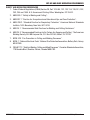
1. Code of Federal Regulations (OSHA) Section 29, Part 1910.95, 132, 133, 134, 139, 251, 252,
253, 254 and 1000. U.S. Government Printing Offi ce, Washington, DC 20402.
2. ANSI Z49.1 “Safety in Welding and Cutting”.
3. ANSI Z87.1 “Practice for Occupational and Educational Eye and Face Protection”.
4. ANSI Z88.2. “Standard Practice for Respiratory Protection”. American National Standards
Institute, 1430 Broadway, New York, NY 10018.
5. AWS F4.1. “Recommended Safe Practices for Welding and Cutting Containers”.
6. AWS C5.3. “Recommended Practices for Air Carbon-Arc Gouging and Cutting”. The American
Welding Society, 550 NW Lejeune Rd., P.O. Box 351040, Miami, FL 33135.
7. NFPA 51B. “Fire Prevention in Cutting and Welding Processes”.
8. NFPA-7. “National Electrical Code”. National Fire Protection Association, Battery Park, Quincy,
MA 02269.
9. CSA W117.2. “Safety in Welding, Cutting and Allied Processes”. Canadian Standards Association,
178 Rexdale Blvd., Rexdale, Ontario, Canada M9W 1R3.
Safety Precautions

2-4
SET-UP AND SAFE OPERATING PROCEDURES
89210002
SECTION 2:
MODEL SPECIFICATIONS
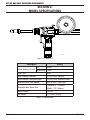
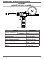
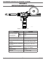
ART# A-11080
Figure 2-1: Spool Gun
Description Rating
Rated Welding Current
C0
2
200A
Mixed Gas 160A
Duty Cycle 60%
Wire Diameter (Normal) 0.023-0.045 (Normal)
Wire Diameter (Stainless Steel) 0.023-0.030 (Stainless Steel)
Maximum Wire Feed Speed 630 in./min. (16m./min.)
Maximum Wire Spool Size
Diameter: 4” (100mm)
Width: 1.75” (45mm)
Motor Voltage 24V DC
Net Weight 12.79 lbs. (5.8kg)
Table 2-2: Specifi cations
Model Specifi cations

SET-UP AND SAFE OPERATING PROCEDURES
3-5
89210002
SECTION 3:
INSTALLATION AND OPERATION
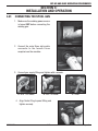
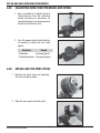
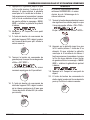
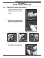
3.01 CONNECTING THE SPOOL GUN
1. Make sure the welding power source
is turned OFF before connecting the
welding gun.
2. Connect the male Dinse style cable
connector to the female Dinse
receptacle on the machine.
3. Connect gas supply fi tting and tighten with a wrench.
3A. Inlet - USA model 3B. Inlet - UK model 3C. Outlet
4. Align Control Plug to panel fi tting and
tighten securely.
Installation and Operation

3-6
SET-UP AND SAFE OPERATING PROCEDURES
89210002
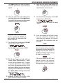
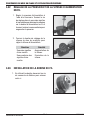
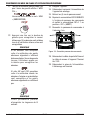
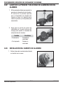
3.02 ADJUSTING WIRE FEED PRESSURE AND SPEED
1. Use a screwdriver to adjust the wire
feed pressure. Turn the adjusting
screw clockwise to decrease, or
counterclockwise to increase pressure
on the wire feed drive rolls.
2. Turn the speed control knob (bottom
of handle) to adjust the wire feed
speed.
Direction Result
Clockwise Increase Speed
Counterclockwise Decrease Speed
3.03 INSTALLING THE WIRE SPOOL
1. Remove the spool cover by loosening
the cover screw by hand.
2. Slide the wire spool onto the shaft.
Installation and Operation

SET-UP AND SAFE OPERATING PROCEDURES
3-7
89210002
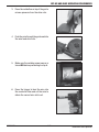
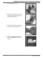
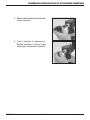
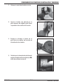
3. Press the red button on top of the gun to
release pressure from the drive rolls.
4. Push the wire through the guide and into
the wire feed drive rolls.
5. Make sure the welding power source is
turned ON before proceeding to step 6.
6. Press the trigger to feed the wire into
the conductor tube and cut the wire to
obtain the correct wire stick-out.
Installation and Operation

3-8
SET-UP AND SAFE OPERATING PROCEDURES
89210002
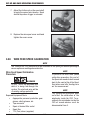
7. Adjust the friction nut on the spool shaft
to apply the correct wire tension. Spool
should stop when trigger is released.
8. Replace the wire spool cover and hand
tighten the cover screw.
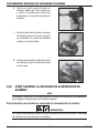
3.04 WIRE FEED SPEED CALIBRATION
NOTE
The Thermal Arc 252i machine must be calibrated to the spool gun before operating to
ensure optimum welding characteristics.
Wire Feed Speed Calibration
Procedure
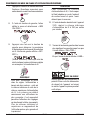
WARNING
DO NOT TOUCH the electrode wire
while it is being fed through the
system. The electrode wire will be
at welding voltage potential.
Required Equipment/Tools:
• Appropriate personal protective gear:
gloves, safety glasses, etc.
• Tape measure
• Spool of desired fi ller metal
• Spool Gun
• T15 (Torx) driver (supplied)
NOTE
To perform the wire feed speed
calibration procedure the end of
the Spool wire needs to be trimmed
back to the contact tip of the Spool
Gun before and after feeding wire
out for measurement.
NOTE
This calibration procedure does
not affect the calibration of the
wirefeeder inside the 252i. To re-
calibrate the wirefeeder inside the
252i all remote devices must be
disconnected from it.
Installation and Operation

SET-UP AND SAFE OPERATING PROCEDURES
3-9
89210002
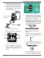
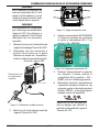
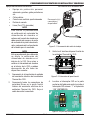
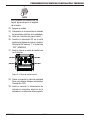
1. Disconnect the input power to the
Thermal Arc 252i welding power supply.
2. Disconnect all Dinse polarity connectors
on the lower front of the Thermal Arc
252i power supply. Leave the control
cable connected.
Disconnect Polarity
Connection(s)
+
-
Front View 252i
Art # A-11081
Figure 3-1: Disconnect Work Lead
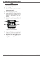
3. Remove (4) front panel screws on the
Thermal Arc 252i.
Art # A-10406
Figure 3-2: Front Panel Removal
4. Locate the SERVICE DIP switch on the
back of the control board and set the
number “1” DIP switch to the “ON”
position.
12
ON
Figure 3-3: Setting DIP Switch
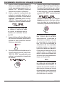
5. Temporarily place the board back in
the unit. The DIP switch will need to be
returned to the “OFF” position when the
calibration process is complete.
6. Re-connect the input power to the
welding power supply and turn it ON. The
left and right displays should show “ERR
30” which means the normal welding
output has been prevented.
NOTE
From this point forward unless
noted all adjustments will be made
using the controls on the Thermal
Arc 252i.
7. Enter Advanced Features Mode by
pressing & releasing Advanced Features
Button.
Advanced
Features
8. Using the left knob, scroll through the
menu list to fi nd and select “WFS CAL
PROC”.
WIRESPEED
A
Left Knob
9. Press and release the left knob to
enter the Wire Feed Speed Calibration
Installation and Operation

3-10
SET-UP AND SAFE OPERATING PROCEDURES
89210002
Procedure. At this point, the left display
will show “SET / SPD1”,
(Low speed value) and the right display
will show the Factory set low speed wire
feed calibration value.
WIRESPEED
A
Left Knob
NOTE
The power supply requires two
values to properly calibrate wire
feed speed. A low feed speed
value and a high feed speed value.
Default speeds span the most
typical jobs. You may choose
alternates that better represent
your work. The closer an upper
or lower speed is to an actual
procedure, the better the accuracy.
NOTE
To perform the wire feed speed
calibration procedure the end of
the Spool wire needs to be trimmed
back to the contact tip of the Spool
Gun before and after feeding wire
out for measurement.
10. Using the right knob on the 252i, adjust
wire feed speed value in the right
display to read 250 for the lower wire
feed speed calibration speed (in units/
minute).
ARC CONTROL
V
Right Knob
11. Turn the left knob clockwise until the left
display shows “PULL / TRIG”.
And the right display shows “LOWR”.
WIRESPEED
A
Left Knob
WARNING
Ensure that all Dinse polarity
connections have been removed
from the front of the unit or live fi ller
metal wire will be present during
this part of the procedure.
12. Pull the gun trigger and hold until wire
feeding stops (Approximately 1 meter
of wire will be spooled out). If trigger
is released before wire stops feeding
on its own, the procedure needs to be
started over. When the wire has stopped
spooling and the left display is showing
the “MEAS / WIRE” message, release the
Spool Gun trigger.
13. Measure its length. Cut off wire at the
same location as when it started.
14. Using the right control knob on the 252i,
adjust the value in the right display to
match the value that was just measured.
ARC CONTROL
V
Right Knob
15. Turn the left control knob until the left
display shows “SET SPD2”.
Installation and Operation

SET-UP AND SAFE OPERATING PROCEDURES
3-11
89210002
The right display will show the default
nominal upper wire feed calibration
speed.
WIRESPEED
A
Left Knob
16. Using the right knob on the 252i, adjust
wire feed speed value in the right display
to read 600 for the upper wire feed speed
calibration speed (in units/minute).
ARC CONTROL
V
Right Knob
NOTE
The speed which is selected should
also be significantly ABOVE the
value used for the lower wire feed
speed calibration.
17. Turn the left knob clockwise until the left
display shows “PULL / TRIG”.
And the right display shows “UPPR”.
WIRESPEED
A
Left Knob
18. Pull the gun trigger and hold until wire
feeding stops (Approximately 1 meter
of wire will be spooled out) If trigger
is released before wire stops feeding
on its own, the procedure needs to be
started over. When the wire has stopped
spooling and the left display is showing
the “MEAS / WIRE” message, release the
Spool Gun trigger.
19. Measure its length. Cut off wire at the
same location as when it started.
20. Using the right control knob, adjust the
value in the right display to match the
value that was just measured.
ARC CONTROL
V
Right Knob
21. Turn the left knob clockwise until the left
display shows “WFS / CAL”.
The right display will show the word
“SAVE”.
WIRESPEED
A
Left Knob
22. Press and release the left knob to save
the new calibration settings. If the
calibration data passes the internal
data checks, the calibration data will
be saved.
NOTE
If the new calibration values pass
internal checks and are accepted,
the operator will briefl y observe the
fl ashing decimal points pattern in
the left hand display when pressing
the knob to save the data.
If the new values do NOT pass
internal checks, the original/
previous data is retained and the
fl ashing decimal point is not shown.
WIRESPEED
A
Left Knob
Installation and Operation

3-12
SET-UP AND SAFE OPERATING PROCEDURES
89210002Installation and Operation
NOTE
This will save the values that were
entered for the length of wire.
23. Turn unit OFF.
24. Disconnect the input power to the
welding power supply.
25. Remove (4) front panel screws.
26. Locate the SERVICE DIP switch on the
back of the control board and set the
number “1” DIP switch to the “OFF”
position.
27. Reinstall the control panel with all (4)
screws.
Art # A-10406
Figure 3-4: Front Control Panel
28. Re-connect the Dinse polarity cable and
the Work Lead to the Thermal Arc 252i.
29. Re-connect the input power to the
welding power supply. Calibration is
complete.

SET-UP AND SAFE OPERATING PROCEDURES
4-13
89210002
SECTION 4:
CARE AND MAINTENANCE
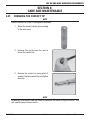
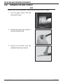
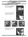
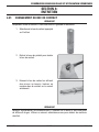
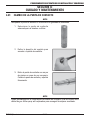
4.01 CHANGING THE CONTACT TIP
NOTE
Replace contact tip if hole is enlarged or deformed.
1. Select the correct contact tip according
to the wire used.
2. Remove the nozzle from the gun to
reveal the contact tip.
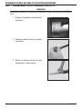
3. Remove the contact tip using pliers if
needed. Replace contact tip and tighten
securely.
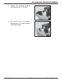
NOTE
Periodically clean spatter from the inside of the nozzle and holes of the gas diffuser. Use
anti-spatter spray for best results.
Care and Maintenance

4-14
SET-UP AND SAFE OPERATING PROCEDURES
89210002
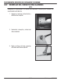
4.02 CHANGING THE WIRE CONDUIT
NOTE
Replace liner if hole is obstructed. Make sure the end of the liner is smooth.
1. Turn the power source OFF and
disconnect the gun.
2. Unscrew the nozzle and remove it
from the conductor tube.
3. Remove the diffuser from the
conductor tube using a wrench.
Care and Maintenance

SET-UP AND SAFE OPERATING PROCEDURES
4-15
89210002
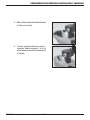
4. Remove the conductor tube by
unscrewing the nut at the base.
5. Pull the liner out and replace.
Repeat steps 1-4 in reverse order to
reassemble the gun.
Care and Maintenance

4-16
SET-UP AND SAFE OPERATING PROCEDURES
89210002
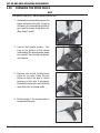
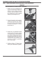
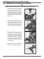
4.03 CHANGING THE DRIVE ROLLS
NOTE
Turn power supply OFF before replacing drive rolls.
1. Remove the screws which secure the
upper and lower drive rolls. It may be
necessary to remove drive roll side of
gun case to change lower drive roll.
(See steps 2 and 3).
2. Loosen four handle screws. Turn
ring on the bottom of the handle
(surrounding the speed control knob)
one-quarter turn counter-clockwise,
and remove.
3. Remove one screw holding each
drive roll in place. Press the red
button on top of the gun to relieve
pressure on the rolls if necessary.
Remove the drive rolls, and install the
new drive rolls in reverse order.
4. Perform steps 1-3 in reverse order to
reassemble the gun
Care and Maintenance
La page est en cours de chargement...
La page est en cours de chargement...
La page est en cours de chargement...
La page est en cours de chargement...
La page est en cours de chargement...
La page est en cours de chargement...
La page est en cours de chargement...
La page est en cours de chargement...
La page est en cours de chargement...
La page est en cours de chargement...
La page est en cours de chargement...
La page est en cours de chargement...
La page est en cours de chargement...
La page est en cours de chargement...
La page est en cours de chargement...
La page est en cours de chargement...
La page est en cours de chargement...
La page est en cours de chargement...
La page est en cours de chargement...
La page est en cours de chargement...
La page est en cours de chargement...
La page est en cours de chargement...
La page est en cours de chargement...
La page est en cours de chargement...
La page est en cours de chargement...
La page est en cours de chargement...
La page est en cours de chargement...
La page est en cours de chargement...
La page est en cours de chargement...
La page est en cours de chargement...
La page est en cours de chargement...
La page est en cours de chargement...
La page est en cours de chargement...
La page est en cours de chargement...
La page est en cours de chargement...
La page est en cours de chargement...
La page est en cours de chargement...
La page est en cours de chargement...
La page est en cours de chargement...
La page est en cours de chargement...
La page est en cours de chargement...
La page est en cours de chargement...
La page est en cours de chargement...
La page est en cours de chargement...
La page est en cours de chargement...
La page est en cours de chargement...
La page est en cours de chargement...
La page est en cours de chargement...
La page est en cours de chargement...
La page est en cours de chargement...
La page est en cours de chargement...
La page est en cours de chargement...
La page est en cours de chargement...
La page est en cours de chargement...
La page est en cours de chargement...
La page est en cours de chargement...
-
 1
1
-
 2
2
-
 3
3
-
 4
4
-
 5
5
-
 6
6
-
 7
7
-
 8
8
-
 9
9
-
 10
10
-
 11
11
-
 12
12
-
 13
13
-
 14
14
-
 15
15
-
 16
16
-
 17
17
-
 18
18
-
 19
19
-
 20
20
-
 21
21
-
 22
22
-
 23
23
-
 24
24
-
 25
25
-
 26
26
-
 27
27
-
 28
28
-
 29
29
-
 30
30
-
 31
31
-
 32
32
-
 33
33
-
 34
34
-
 35
35
-
 36
36
-
 37
37
-
 38
38
-
 39
39
-
 40
40
-
 41
41
-
 42
42
-
 43
43
-
 44
44
-
 45
45
-
 46
46
-
 47
47
-
 48
48
-
 49
49
-
 50
50
-
 51
51
-
 52
52
-
 53
53
-
 54
54
-
 55
55
-
 56
56
-
 57
57
-
 58
58
-
 59
59
-
 60
60
-
 61
61
-
 62
62
-
 63
63
-
 64
64
-
 65
65
-
 66
66
-
 67
67
-
 68
68
-
 69
69
-
 70
70
-
 71
71
-
 72
72
-
 73
73
-
 74
74
-
 75
75
-
 76
76


ESAB Spool Gun Manuel utilisateur
- Catégorie
- Système de soudage
- Taper
- Manuel utilisateur
dans d''autres langues
- English: ESAB Spool Gun User manual
- español: ESAB Spool Gun Manual de usuario
Documents connexes
-
 Tweco Spool Gun Spool Gun Manuel utilisateur
-
 Tweco Welding and Cutting Operations Manuel utilisateur
-
 Tweco Tweco Spool Gun Manuel utilisateur
-
 Tweco Air-Cooled 350 AMP 450 AMP Water-Cooled 400 AMP 500 AMP PulseMaster™ Mig Gun Manuel utilisateur
-
ESAB FABRICATOR252i Manuel utilisateur
-
 Tweco ULTRAFEED® VAF-4 Wirefeeder Manuel utilisateur
-
 Tweco ULTRAFEED® VAF-4HD Wirefeeder Manuel utilisateur
-
ESAB FABRICATOR® 141i 3-IN-1 Multi Process Welding Systems Manuel utilisateur
-
 Tweco FABRICATOR® 141i 3-IN-1 Multi Process Welding Systems Manuel utilisateur
-