
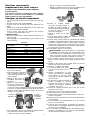
• Remove the collar (#395203).
• Remove the spring by turning it slightly as it is pulled off.
• Remove the retainer band (#603561) from the spring retainer
(#395204).
6. Remove the spring retainer
(white plastic ring, #395204) by
spreading it enough to clear the
body of the engine and pulling it off.
7. Remove the bulkhead (#395215).
8. At this point, all the o-rings identified
in the exploded view are exposed on
the tool.
9. Remove all o-rings and the cylinder seal (#390140) as identi-
fied in the Parts Drawing and in the o-ring identifier Table 1.
Replace all o-rings, coating each one with a layer of supplied
grease to insure proper seating when reinstalled. No grease is
needed on the check seal.
10. Reassemble the engine in reverse order.
CAUTION: The o-ring in the poly bag (#606640) must only be
used in the location indicated on the Parts Drawing. The use
of any other o-ring in this position could result in excessive
wear over the life of the tool and potential inadvertent firing.
11. Before installing engine into the housing, make sure bumper
(#395213) is properly seated in the bottom of the frame.
12. Insert engine assembly into frame and push down as far as
possible.
13. Replace piston o-ring (#608611)
on driver blade/piston assembly.
Insert driver blade/piston assembly
into cylinder.
14. Liberally apply supplied grease to the inner and outer exhaust
o-rings before assembling the top cap to the engine frame.
15. With a gentle turning motion, assemble
top cap onto engine and frame. The
cap should slide easily. If not, remove
cap and reassemble.
16. Push downward to fully seat cap of
frame.
17. Replace and tighten top cap screws.
18. Tighten screws snugly to prevent leaks.
19. Ensure trigger and contact trip are working smoothly.
20. Set pressure on compressor or air line at 80 psi.
21. Pointing tool in safe direction, connect tool to air supply. Tool
must not leak air.
22. Check for proper operation of tool. If tool continues to leak air
or if problems persist, take nailer to a D
EWALT service center.
23. If warning labels are missing or damaged, request free replace-
ments from a D
EWALT service center.
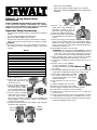
D518001 - O-ring Replacement
Instructions
DEWALT FRAMING NAILERS MODELS D51823 AND D51845
If you should have difficulty understanding the following
instructions contact a D
EWALT service center or an authorized
D
EWALT service person, or call 1-800-4-DEWALT.
Important Safety Instructions
• Read and understand tool instruction manual before attempting
repairs.
• Use only genuine D
EWALT replacement parts.
• Always wear ANSI compliant eye protection.
• Disconnect air from tool and remove all nails before servicing.
• Always point tool in safe direction when reconnecting air supply.
CAUTION:
• Do not allow dirt, dust or other foreign materials to enter the tool.
• Be careful not to scratch or damage the o-rings or any internal
surfaces.
1. Disconnect air supply and
remove nails from tool.
2. Remove the 4 top cap screws
using a 5mm Allen wrench and
remove the top cap.
3. Pull out engine assembly and
piston/driver blade assembly.
If necessary, pry the cylinder
out of housing using the han-
dle of a hammer or other tool.
4. Place the engine assembly
upside down on work surface
so that the spring is toward
the top. Use one hand to compress the collar (#395203) and
Spring (#603413) so that the lower cylinder o-ring (#390146
w/ 1 blue dot) is exposed.
5. With the free hand, remove the lower cylinder o-ring and gently
release the collar and spring.
COLLAR
SPRING
LOWER
CYLINDER
O-RING
O-RING DESC. # IN KIT PART # IDENTIFIER
Inner Exhaust 1 390164 White Dot
Inner Cylinder 1 606640 In poly bag
Outer Exhaust 1 390160 Orange Dot
Outer Cylinder 1 612096 White O-ring
Outer Bulkhead 2 390156 Green Dot
Lower Cylinder 1 390146 Blue Dot
OTHER INCLUDED PARTS
Retainer Band 1 603561
Cylinder Seal 1 390140
Check Seal 1 390159
Grease Tube 2 606112
Piston O-ring 1 608611
TABLE 1

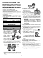
• Enlever le ressort en le tournant légèrement.
• Dégager la bande de retenue (no de pièce 603561) de la
coupelle d’appui du ressort (no de pièce 395204).
6. Enlever la coupelle d’appui
du ressort (la bague blanche en
plastique, no de pièce 395204) en
écartant suffisamment pour dégager
le corps du moteur; tirer sur ce
dernier pour le dégager.
7. Enlever la cloison (no de pièce
395215).
8. Tous les joints toriques montrés dans l’illustration en éclaté
devraient maintenant être exposés.
9. Enlevez toutes les joints torques et le Scellement du cylindre
(# 390140) comme identifié dans les pièces dessinant et dans
le tableau 1. Remplacez toutes les joints torques, enduisant
chacun d'une couche de graisse fournie pour assurer l'alloca-
tion des places appropriée une fois réinstallé. Aucune graisse
n'est nécessaire sur le joint de contrôle.
10. Réassembler le moteur en sens inverse.
MISE EN GARDE : le joint torique dans le sac en plastique
(no 606640) ne doit être utilisé qu’à l’endroit indiqué sur le
schéma des pièces. L’utilisation de tout autre joint torique
dans cette position pourrait causer l’usure excessive de
l’outil et entraîner la décharge accidentelle de ce dernier.
11. Avant d’installer le moteur dans le boîtier, s’assurer que la
butée (no de pièce 395213) est bien enfoncée dans le bâti de
l’outil.
12. Replacer le bloc moteur dans le bâtide l’outil et le pousser
jusqu’au fond, aussi loin que possible.
13. Remettre l’ensemble piston/lame
(no de pièce 608611) de l’enfon-
ceur, puis insérer celui-ci dans le
cylindre.
14. Graisser abondamment les joints
toriques des déflecteurs d’échappe-
ment intérieur et extérieur avant
d’assembler le capuchon supérieur au
carter du moteur.
15. En effectuant un léger mouvement de
rotation, assembler le capuchon
supérieur sur le moteur et le carter. Le
capuchon devrait glisser facilement. Sinon, le retirer et
l’assembler de nouveau.
16. Pousser le capuchon fermement vers le bas afin de bien
l’enclencher sur le carter.
17. Replacer et serrer les vis du capuchon supérieur.
18. Serrer fermement les vis pour prévenir les fuites.
19. S’assurer que la gâchette et le déclencheur par contact fonc-
tionnent correctement.
20. Régler la pression du compresseur ou du circuit d’alimentation
en air à 80 lb/po
2
.
21. Raccorder l’outil au circuit d’alimentation en air, en s’assurant
qu’il n’y a aucune fuite d’air.
22. S’assurer que l’outil fonctionne correctement. En présence
d’une fuite d’air ou d’un problème quelconque, apporter l’outil à
un centre de service D
EWALT.
23. En cas de perte ou d’endommagement des étiquettes d’aver-
tissement, communiquer avec un centre de service D
EWALT
afin d’en obtenir de nouvelles sans frais.
2
Directives concernant le
remplacement des joints toriques
CLOUEURS POUR CHARPENTES DEWALT MODÈLES
D51823 ET D51845
Si les directives suivantes ne semblent pas claires, communi-
quer avec un centre de service D
EWALT ou un technicien
D
EWALT qualifié, ou appel 1-800-4-DEWALT.
Consignes de sécurité importantes
• Lire et comprendre le manuel avant d’entreprendre des répa-
rations.
• N’utiliser que des pièces d’origine D
EWALT.
• Toujours porter des lunettes de protection approuvées par
ANSI.
• Débrancher l’outil du circuit d’alimentation en air et retirer tous
les clous avant d’effectuer l’entretien.
• Toujours pointer l’outil dans une direction sûre lorsqu’on
raccorde le circuit d’alimentation en air.
MISE EN GARDE :
• Ne laisser aucune saleté ou matière étrangère pénétrer à l’in-
térieur de l’outil.
• Éviter d’égratigner ou d’endommager les joints toriques et les
surfaces internes.
1. S’assurer que le boyau d’air
est débranché de l’outil. Retirer
tous les clous de l’outil.
2. Enlever les quatre vis qui retien-
nent le capuchon supérieur au
moyen d’une clé Allen de 5 mm;
retirer ce dernier.
3. Dégager le bloc moteur et
l’ensemble piston/lame de
l’enfonceur.
4. Déposer le bloc moteur à
l’envers sur la surface de tra-
vail de manière à orienter le
ressort vers le haut. Comprimer le collier (no de pièce 395203)
et le ressort (no de pièce 603413) d’une main afin de mettre à
découvert le joint torique du cylindre inférieur (no de pièce
390146, avec un point bleu).
5. Avec l’autre main, retirer le joint torique du cylindre inférieur,
puis relâcher doucement le collier et le ressort.
• Retirer le collier (no de pièce 395203).
COLLIER
RESSORT
JOINT
TORIQUE DU
CYLINDRE
INFÉRIEUR
Description des Quant. No de Identificateur
joints toriques pièce
Déflecteur d’échappement 1 390164 Point blanc
intérieur
Cylindre intérieur 1 606640 Dans le sac en plastique
Cloisons extérieures 1 390160 Point orange
Cylindre extérieur 1 612096 Joints torques blanc
Cloisons extérieures 2 390156 Point vert
Cylindre inférieur 1 1390146 Point bleu
Autres pièces fournies
Band de retenue 1 603561
Scellement du cylindre 1 390140
Scellement de contrôle 1 390159
Tubes de graissage 2 606112
Joints torques de piston 1 608611
TABLEAU 1
La page est en cours de chargement...

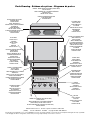
BULKHEAD
PART# 395215
CLOISON
NO DE PIÈCE
395215
TABIQUE
PARTE# 395215
SPRING RETAINER
PART #395204
COUPELLE D’APPUI
DU RESSORT
NO DE PIÈCE 395204
RETÉN DE RESORTE
PARTE#395204
SPRING
PART# 603413
RESSORT
NO DE PIÈCE 603413
RESORTE
PARTE# 603413
OUTER CYLINDER O-RING
(WHITE O-RING)
PART# 612096
JOINT TORIQUE DU
CYLINDRE EXTÉRIEUR
(JOINT TORIQUE BLANC)
NO DE PIÈCE 612096
O-RING EXTERIOR DE
CILINDRO
(O-RING BLANCO)
PARTE# 612096
RETAINER BAND
PART# 603561
BANDE DE RETENUE
NO DE PIÈCE 603561
BANDA DE RETÉN
PARTE# 603561
INNER CYLINDER O-RING
(IN POLYBAG)
PART# 606640
JOINT TORIQUE DU CYLINDRE
INTÉRIEUR
(DANS LE SAC EN PLASTIQUE)
NO DE PIÈCE 606640
O-RING INTERIOR DE CILINDRO
(EN SACO PLÁSTICO)
PARTE# 606640
OUTER EXHAUST O-RING
(ORANGE DOT)
PART# 390160
JOINT TORIQUE DU
DÉFLECTEUR D’ÉCHAPPEMENT
EXTÉRIEUR
(POINT ORANGE)
NO DE PIÈCE 390160
O-RING EXTERIOR DE ESCAPE
(PUNTO NARANJA)
PARTE#390160
COLLAR
PART# 395203
COLLIER
NO DE PIÈCE 395203
COLLARÕN
PARTE# 395203
LOWER CYLINDER O-RING (BLUE DOT)
PART# 390146
JOINT TORIQUE DU CYLINDRE INFÉRIEUR
(POINT BLEU) NO DE PIÈCE 390146
O-RING INFERIOR DE CILINDRO (PUNTO AZUL)
PARTE# 390146
OUTER BULKHEAD O-RINGS
(GREEN DOT)
PART# 390156
JOINTS TORIQUES DE LA
CLOISON EXTÉRIEURE
(POINT VERT)
NO DE PIÈCE 390156
O-RINGS EXTERIORES
DE TABIQUE
(PUNTO VERDE)
PARTE# 390156
INSIDE - INNER EXHAUST O-RING (WHITE DOT)
PART# 390164
JOINT TORIQUE DU CYLINDRE INTÉRIEUR
(POINT BLANC)
NO DE PIÈCE 390164
O-RING INTERIOR DE ESCAPE
(PUNTO BLANCO)
PARTE#390164
CHECK SEAL
PART# 390159
SCELLEMENT DE
CONTRÔLE
NO DE PIÈCE 390159
EMPAQUE DE CHECK
PARTE# 390159
CYLINDER SEAL
PART# 390140
SCELLEMENT DU
CYLINDRE
NO DE PIÈCE 390140
EMPAQUE DE
CILINDRO
PARTE# 390140
Parts Drawing - Schéma des pièces - Diagrama de partes
DEWALT Industrial Tool Co., 701 East Joppa Road, Baltimore, MD 21286
(JUN06) Form No. 606118-02 D518001 Copyright © 2002, 2006 DEWALT
The following are trademarks for one or more DEWALT power tools: the yellow and black color scheme; the “D” shaped air intake grill; the array of pyramids
on the handgrip; the kit box configuration; and the array of lozenge-shaped humps on the surface of the tool.
-
 1
1
-
 2
2
-
 3
3
-
 4
4


dans d''autres langues
- English: DeWalt D518001 User manual
- español: DeWalt D518001 Manual de usuario
Documents connexes
-
DeWalt D510005 Manuel utilisateur
-
-
-
-
-
-
-
-
-