
i
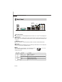
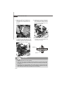
MS-7514 (v2.X) Mainboard
G52-75141XB
P45 Neo3 V2/
P43 Neo3 V2 Series
La page est en cours de chargement...
La page est en cours de chargement...
La page est en cours de chargement...
La page est en cours de chargement...
La page est en cours de chargement...
La page est en cours de chargement...
La page est en cours de chargement...

ix
Français.....................................................................................................................Fr-1
Spécifications.....................................................................................................Fr-2
Guide rapide des composants..........................................................................Fr-4
Processeur : CPU...............................................................................................Fr-5
Mémoire...............................................................................................................Fr-9
Connecteur d’alimentation...............................................................................Fr-11
Panneau arrière................................................................................................Fr-12
Connecteurs.....................................................................................................Fr-14
Cavalier.............................................................................................................Fr-21
Boutons.............................................................................................................Fr-22
Interrupteur.......................................................................................................Fr-23
Slots...................................................................................................................Fr-24
Indicateurs de statuts de LED.........................................................................Fr-25
Réglages BIOS..................................................................................................Fr-26
Information de Logiciel.....................................................................................Fr-35
Русский ....................................................................................................................Ru-1
Характеристики ...............................................................................................Ru-2
Руководство по размещению компонентов ..............................................Ru-4
CPU (Центральный процессор).....................................................................Ru-5
Память ..............................................................................................................Ru-9
Разъем питания .............................................................................................Ru-11
Задняя панель ...............................................................................................Ru-12
Разъемы ..........................................................................................................Ru-14
Перемычки......................................................................................................Ru-21
Кнопки .............................................................................................................Ru-22
Переключатели ..............................................................................................Ru-23
Слоты ...............................................................................................................Ru-24
Световые индикаторы .................................................................................Ru-25
Настройка BIOS..............................................................................................Ru-26
Сведения о программном обеспечении ...................................................Ru-35

En-1
English
P45 Neo3 V2/
P43 Neo3 V2 Series
User’s Guide
English
La page est en cours de chargement...
La page est en cours de chargement...

En-4
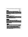
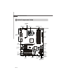
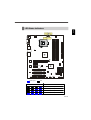
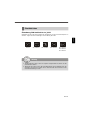
MS-7514 Mainboard
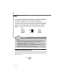
ON
123
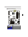
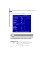
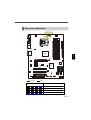
Quick Components Guide
CPU, En-5
DDR2 DIMMs,
En-9
JPWR1,
En-11
SATA,
En-15
JUSB1~3,
En-20
J1394_1,
En-17
FDD1,
En-14
JCD1,
En-18
JTPM1,
En-19
JAUD1,
En-19
PCI,
En-24
Back Panel,
En-12
PWR1, En-11
JCI1, En-16
JFP2, JFP1
En-18
SYSFAN1,
En-16
SYSFAN2,
En-16
CPUFAN1, En-16
IDE1,
En-14
JSP1,
En-17
PCIE,
En-24
JBAT1,
En-21
OC_SW1,
En-23
RESET1,
En-22
POWER1,
En-22
CLR_CMOS1,
En-22
La page est en cours de chargement...
La page est en cours de chargement...
La page est en cours de chargement...
La page est en cours de chargement...
La page est en cours de chargement...
La page est en cours de chargement...

En-11
English
Power Supply
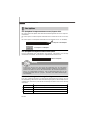
PIN SIGNAL
13 +3.3V
14 -12V
15 GND
16 PS-ON#
17 GND
18 GND
19 GND
20 Res
21 +5V
22 +5V
23 +5V
24 GND
PIN SIGNAL
1 +3.3V
2 +3.3V
3 GND
4 +5V
5 GND
6 +5V
7 GND
8 PWR OK
9 5VSB
10 +12V
11 +12V
12 +3.3V
Pin Definition
pin 12
pin 13
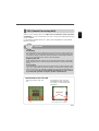
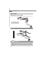
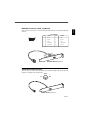
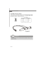
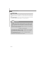
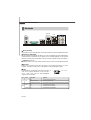
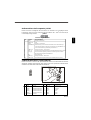
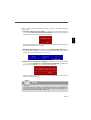
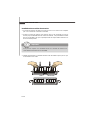
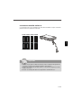
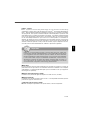
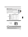
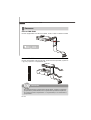
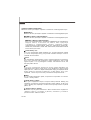
ATX 24-Pin Power Connector: JPWR1
This connector allows you to connect an ATX 24-pin power supply.
To connect the ATX 24-pin power supply, make sure the plug of the
power supply is inserted in the proper orientation and the pins are
aligned. Then push down the power supply firmly into the connector.
You may use the 20-pin ATX power supply as you like. If you’d like
to use the 20-pin ATX power supply, please plug your power sup-
ply along with pin 1 & pin 13 (refer to the image at the right hand).
ATX 4-pin Power Connector: PWR1
This power connector is used to provide power to the CPU.
1
JPWR1
12
24
13
PIN SIGNAL
1 GND
2 GND
3 12V
4 12V
Pin Definition
PWR1
Important
1. Make sure that all the connectors are connected to proper ATX power sup-
plies to ensure stable operation of the mainboard.
2. Power supply of 400 watts (and above) is highly recommended for system
stability.
13
4
2
La page est en cours de chargement...
La page est en cours de chargement...
La page est en cours de chargement...
La page est en cours de chargement...
La page est en cours de chargement...

En-17
English
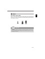
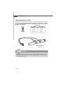
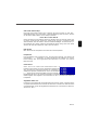
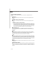
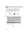
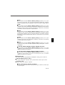
IEEE1394 Connector: J1394_1 (optional)
This connector allows you to connect the IEEE1394 device via an optional IEEE1394
bracket.
S/PDIF Bracket (optional)
S/PDIF-Out Connector: JSP1
This connector is used to connect S/PDIF (Sony & Philips Digital Interconnect Format)
interface for digital audio transmission.
JSP1
VCC
SPDIF
GND
J1394_1
1
2
9
10
Pin Definition
PIN SIGNAL PIN SIGNAL
1 TPA+ 2 TPA-
3 Ground 4 Ground
5 TPB+ 6 TPB-
7 Cable power 8 Cable power
9 Key (no pin) 10 Ground
IEEE1394 Bracket (optional)

En-18
MS-7514 Mainboard
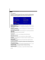
PIN SIGNAL DESCRIPTION
1 HD_LED + Hard disk LED pull-up
2 FP PWR/SLP MSG LED pull-up
3 HD_LED - Hard disk active LED
4 FP PWR/SLP MSG LED pull-up
5 RST_SW - Reset Switch low reference pull-down to GND
6 PWR_SW + Power Switch high reference pull-up
7 RST_SW + Reset Switch high reference pull-up
8 PWR_SW - Power Switch low reference pull-down to GND
9 RSVD_DNU Reserved. Do not use.
JFP1 Pin Definition
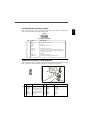
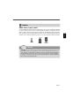
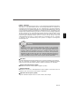
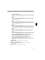
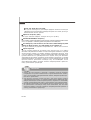
Front Panel Connectors: JFP1, JFP2
These connectors are for electrical connection to the front panel switches and LEDs.
The JFP1 is compliant with Intel
®
Front Panel I/O Connectivity Design Guide.
PIN SIGNAL DESCRIPTION
1 GND Ground
2 SPK- Speaker-
3 SLED Suspend LED
4 BUZ+ Buzzer+
5 PLED Power LED
6 BUZ- Buzzer-
7 NC No connection
8 SPK+ Speaker+
JFP2 Pin Definition
1
2
9
10
JFP1
HDD
LED
Reset
Switch
Power
LED
Power
Switch
+
+
+
- -
-
7
8
Power
LED
Speaker
1
2
JFP2
-
-
+
+
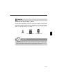
CD-In Connector: JCD1
This connector is provided for external audio input.
JCD1
GND
R
L

En-19
English
Front Panel Audio Connector: JAUD1
This connector allows you to connect the front panel audio and is compliant with
Intel
®
Front Panel I/O Connectivity Design Guide.
TPM Module Connector: JTPM1 (optinoal)
This connector connects to a TPM (Trusted Platform Module) module (optional). Please
refer to the TPM security platform manual for more details and usages.
Pin Signal Description Pin Signal Description
1 LCLK LPC clock 2 3V_STB 3V standby power
3 LRST# LPC reset 4 VCC3 3.3V power
5 LAD0 LPC address & data pin0 6 SIRQ Serial IRQ
7 LAD1 LPC address & data pin1 8 VCC5 5V power
9 LAD2 LPC address & data pin2 10 KEY No pin
11 LAD3 LPC address & data pin3 12 GND Ground
13 LFRAME# LPC Frame 14 GND Ground
PIN SIGNAL DESCRIPTION
1 MIC_L Microphone - Left channel
2 GND Ground
3 MIC_R Microphone - Right channel
4 NC
5 LINE out_R Analog Port - Right channel
6 MIC_JD Jack detection return from front panel microphone JACK1
7 Front_JD Jack detection sense line from the High Definition Audio CODEC
jack detection resistor network
8 NC No control
9 LINE out_L Analog Port - Left channel
10 LINEout_JD Jack detection return from front panel JACK2
21
1413
HD Audio Pin Definition
JAUD1
1
2
9
10
La page est en cours de chargement...
La page est en cours de chargement...
La page est en cours de chargement...

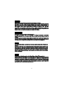
En-23
English
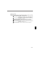
Switch
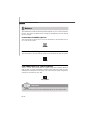
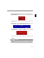
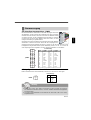
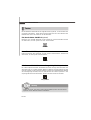
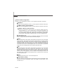
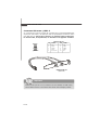
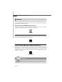
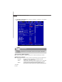
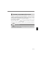
Hardware Overclock FSB Switch: OC_SW1
You can overclock the FSB to increase the processor frequency by changing the
switch OC_SW1. Follow the instructions below to set the FSB.
ON
123
ON
123
ON
123
ON
123
ON
123
Default
200->266 MHz 200->333 MHz 200->400 MHz
266->400 MHz
333->400 MHz
266->333 MHz
Important
1. Make sure that you power off the system before changing the switch.
2. Overclocking may cause instability or crash during boot, then please set
the switch to default setting.
La page est en cours de chargement...

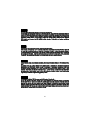
En-25
English
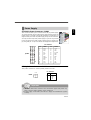
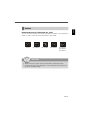
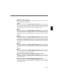
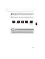
LED Status Indicators
Blue Light Off
LED4 LED3 LED2 LED1 Mode
CPU is in 1 phase power mode.
CPU is in 2 phase power mode.
CPU is in 3 phase power mode.
CPU is in 4 phase power mode.
LED4
LED2
LED3 LED1
ON
123
La page est en cours de chargement...
La page est en cours de chargement...
La page est en cours de chargement...
La page est en cours de chargement...
La page est en cours de chargement...
La page est en cours de chargement...
La page est en cours de chargement...
La page est en cours de chargement...
La page est en cours de chargement...
La page est en cours de chargement...

De-1
Deutsch
P45 Neo3 V2 /
P43 Neo3 V2 Serie
Benutzerhandbuch
Deutsch
La page est en cours de chargement...
La page est en cours de chargement...

De-4
MS-7514 Mainboard
ON
123
Komponenten-Übersicht
CPU, De-5
DDR2 DIMMs,
De-9
JPWR1,
De-11
SATA,
De-15
JUSB1~3,
De-20
J1394_1,
De-17
FDD1,
De-14
JCD1,
De-18
JTPM1,
De-19
JAUD1,
De-19
PCI,
De-24
Back Panel,
De-12
PWR1, De-11
JCI1, De-16
JFP2, JFP1
De-18
SYSFAN1,
De-16
SYSFAN2,
De-16
CPUFAN1, De-16
IDE1,
De-14
JSP1,
De-17
PCIE,
De-24
JBAT1,
De-21
OC_SW1,
De-23
RESET1,
De-22
POWER1,
De-22
CLR_CMOS1,
De-22
La page est en cours de chargement...
La page est en cours de chargement...
La page est en cours de chargement...
La page est en cours de chargement...
La page est en cours de chargement...
La page est en cours de chargement...
La page est en cours de chargement...
La page est en cours de chargement...
La page est en cours de chargement...
La page est en cours de chargement...
La page est en cours de chargement...
La page est en cours de chargement...
La page est en cours de chargement...

De-18
MS-7514 Mainboard
Frontpanel Anschlüsse: JFP1, JFP2
Diese Anschlüsse sind für das Frontpanel. Sie dienen zum Anschluss der Schalter
und LEDs des Frontpanels. JFP1 erfüllt die Anforderungen des “Intel Front Panel I/O
Connectivity Design Guide“.
POL SIGNAL BESCHREIBUNG
1 GND Ground
2 SPK- Speaker-
3 SLED Suspend LED
4 BUZ+ Buzzer+
5 PLED Power LED
6 BUZ- Buzzer-
7 NC No connection
8 SPK+ Speaker+
JFP2 Polzuweisung
1
2
9
10
JFP1
HDD
LED
Reset
Switch
Power
LED
Power
Switch
+
+
+
- -
-
7
8
Power
LED
Speaker
1
2
JFP2
-
-
+
+
CD-Eingang: JCD1
Dieser Anschluss wird für externen Audioeingang zur Verfügung gestellt.
JCD1
GND
R
L
POL SIGNAL BESCHREIBUNG
1 HD_LED + Festplatten-LED-Pullup
2 FP PWR/SLP Meldungs-LED-Pullup
3 HD_LED - Festplattenaktivitäts-LED
4 FP PWR/SLP Meldungs-LED-Pullup
5 RST_SW - Rü ckstellschalter-Pulldown auf Erde mit kleinem Bezugswert
6 PWR_SW + Stromschalter-Pullup mit großem Bezugswert
7 RST_SW + Rückstellschalter-Pullup mit großem Bezugswert
8 PWR_SW - Stromschalter-Pulldown auf Erde mit kleinem Bezugswert
9 RSVD_DNU Reserviert. Nicht benutzen.
JFP1 Polzuweisung
La page est en cours de chargement...
La page est en cours de chargement...
La page est en cours de chargement...
La page est en cours de chargement...

De-23
Deutsch
Steckbrücken
Übertaktung FSB Steckbrücke: OC_SW1
Übertaken Sie den FSB durch ändern der Steckbrücke, um die Prozessorfrequenz zu
erhöhen. Folgen Sie den Anleitungen zur Einstellung des FSB.
ON
123
ON
123
ON
123
ON
123
ON
123
Default
200->266 MHz 200->333 MHz 200->400 MHz
266->400 MHz
333->400 MHz
266->333 MHz
Wichtig
1. Stellen bitte Sie sicher, dass das System ausgeschaltet ist, bevor Sie die
Steckbrücke ändern.
2. Während des Starts kann die HW-Übertaktung die Instabilitat oder der
Abstürze verursachen. Stellen Sie in diesem Falle den Schalter auf die
Standardeinstellung zurück.
La page est en cours de chargement...

De-25
Deutsch
LED Statusdikatoren
hellblau Aus
LED4 LED3 LED2 LED1 Mode
CPU ist in Strommodus 1.
CPU ist in Strommodus 2.
CPU ist in Strommodus 3.
CPU ist in Strommodus 4.
LED4
LED2
LED3 LED1
ON
123
La page est en cours de chargement...
La page est en cours de chargement...
La page est en cours de chargement...
La page est en cours de chargement...
La page est en cours de chargement...
La page est en cours de chargement...
La page est en cours de chargement...
La page est en cours de chargement...
La page est en cours de chargement...
La page est en cours de chargement...

Fr-1
Français
P45 Neo3 V2/
P43 Neo3 V2 Séries
Guide d’utilisation
Français

Fr-2
Carte mère MS-7514
Spécifications
Processeurs Supportés
- Processeurs Intel
®
Core 2 Extreme, Core 2 Quad, Core 2 Duo,
Pentium Dual-Core et Celeron Dual-Core dans le paquet LGA775
- Intel
®
prochaine gégération 45 nm Multi-core CPU
*(Pour plus d’informations sur le CPU, veuillez visiter
http://global.msi.com.tw/index.php?func=cpuform)
FSB Supporté
- 1600*(OC)/ 1333/ 1066/ 800 MHz
Chipset
- North Bridge : Chipset Intel
®
P45/ P43
- South Bridge : Chipset Intel
®
ICH10/ ICH10R
Mémoire supportée
- 4 DDR2 DIMMs supportent DDR2 1066**(OC)/ 800/ 667 SDRAM
(240pin / 1.8V / 16GB Max)
**(Pour plus d’informations sur les composants compatibles,
veuillez visiter http://global.msi.com.tw/index.php?
func=testreport)
LAN
- Supporte PCIE LAN 10/100/1000 Fast Ethernet par Realtek 8111C
Audio
- Puce intégrée par Realtek
®
ALC888
- 8-canaux audio flexibles avec détection de jack
- Compatible avec les spécifications d’Azalia 1.0
- Compatible avec les spécifications de Microsoft Vista Premium
IDE
- 1 port IDE par JMicron JMB363
- Supporte le mode Ultra DMA 66/100/133
- Supporte les modes d’opération PIO, Bus Master
SATA
- 6 ports SATAII par ICH10/ ICH10R (SATA1~6)
- 2 ports SATAII par JMicron JMB363 (SATA7~8)
- Supporte le stockage et un taux de transfert jusqu’à 3 Gb/s
RAID
- SATA1~6 supportent le mode RAID 0/ 1/ 5/ 10/ JBOD par ICH10R
- SATA7 et SATA8 supportent le mode RAID 0/ RAID1/ JBOD par
JMicron JMB363
1394 (optionnel)
- Supporte 1394 par JMicron JMB381

Fr-3
Français
Disquette
- 1 port disquette
- Supporte 1 FDD avec 360KB, 720KB, 1.2MB, 1.44MB et 2.88MB
Connecteurs
Panneau arrière
- 1 port souris PS/2
- 1 port claiver PS/2
- 1 port sérial
- 6 ports USB 2.0
- 1 jack LAN
- 6 jacks audio flexibles
- 1 port 1394 (optionnel)
Connecteurs / boutons intégrés
- 3 connecteurs USB 2.0
- 1 connecteur 1394 (optionnel)
- 1 connecteur châssis intrusion
- 1 connecteur S/PDIF-out
- 1 connecteur CD-in
- 1 connecteur audio avant
- 1 connecteur Module TPM (optionnel)
- 1 interrupteur du FSB d’overclocking du Matériel
- 1 bouton de réinitialisation (optionnel)
- 1 bouton d’alimentation (optionnel)
- 1 bouton d’effacement CMOS (optionnel)
TPM (optionnel)
- Supporte TPM
Slots
- 1 slot PCI Express x16, supporte jusqu’à la vitesse de PCI Express
2.0 x16
- 2 slots PCI Express x1
- 3 slots PCI, supportent l’interface bus PCI 3.3V/ 5V
Dimension
- ATX (30.5cm X 24.5cm)
Montage
- 9 trous de montage

Fr-4
Carte mère MS-7514
ON
123
Guide rapide des composants
CPU, Fr-5
DDR2 DIMMs,
Fr-9
JPWR1,
Fr-11
SATA,
Fr-15
JUSB1~3,
Fr-20
J1394_1,
Fr-17
FDD1,
Fr-14
JCD1,
Fr-18
JTPM1,
Fr-19
JAUD1,
Fr-19
PCI,
Fr-24
Back Panel,
Fr-12
PWR1, Fr-11
JCI1, Fr-16
JFP2, JFP1
Fr-18
SYSFAN1,
Fr-16
SYSFAN2,
Fr-16
CPUFAN1, Fr-16
IDE1,
Fr-14
JSP1,
Fr-17
PCIE,
Fr-24
JBAT1,
Fr-21
OC_SW1,
Fr-23
RESET1,
Fr-22
POWER1,
Fr-22
CLR_CMOS1,
Fr-22

Fr-5
Français
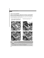
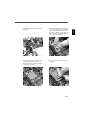
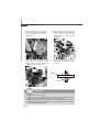
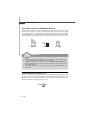
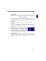
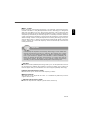
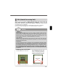
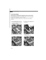
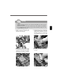
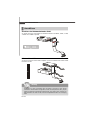
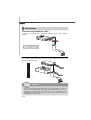
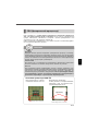
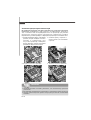
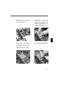
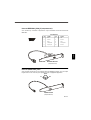
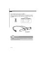
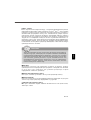
Processeur : CPU
Quand vous installez le CPU, veuillez vous assurer que l’unité centrale est
équipée d’un ventilateur de refroidissement attaché sur le dessus pour
éviter la surchauffe. Si vous n’en avez pas, contactez votre revendeur pour en
acheter et installez les avant d’allumer votre ordinateur.
Pour plus d’informations sur le CPU, veuillez visiter http://global.msi.com.tw/index.
php?func=cpuform
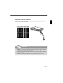
Introduction du LGA 775 CPU
La surface du LGA 775 CPU.
N’oubliez pas d’appliquer une
couche d’enduit thermique pour
améliorer la dissipation de la
chaleur.
La face de la galette à
contacts du LGA 775 CPU.
Important
Surchauffe
La surchauffe endommage sérieusement l’unité centrale et le système.
Assurez-vous toujours que le ventilateur de refroidissement fonctionne
correctement pour protéger l’unité centrale contre la surchauffe. Assurez-
vous d’appliquer une couche d’enduit thermique (ou film thermique) entre
l’unité centrale et le dissipateur thermique pour améliorer la dissipation de
la chaleur.
Remplacement de l’unité centrale
Lorsque vous remplacez l’unité centrale, commencez toujours par couper
l’alimentation électrique de l’ATX ou par débrancher le cordon d’alimentation
de la prise mise à la terre pour garantir la sécurité de l’unité centrale.
Overclocking
Cette carte mère supporte l’overclocking. Néanmoins, veuillez vous assurer
que vos composants soient capables de tolérer ces configurations anormales,
lors d’overclocking. Tout envie d’opérer au dessus des spécifications du
produit n’est pas recommandé. Nous ne garantissons pas les dommages
et risques causés par les opérations insuffisantes ou au dessus des
spécifications du produit.
Le triangle jaune est l ’indicateur du Pin 1.Le triangle jaune est l ’indicateur du Pin 1.
Clé d’alignement
Clé d’ alignement
La page est en cours de chargement...
La page est en cours de chargement...
La page est en cours de chargement...
La page est en cours de chargement...
La page est en cours de chargement...
La page est en cours de chargement...
La page est en cours de chargement...
La page est en cours de chargement...
La page est en cours de chargement...
La page est en cours de chargement...
La page est en cours de chargement...
La page est en cours de chargement...
La page est en cours de chargement...
La page est en cours de chargement...
La page est en cours de chargement...
La page est en cours de chargement...
La page est en cours de chargement...
La page est en cours de chargement...
La page est en cours de chargement...
La page est en cours de chargement...
La page est en cours de chargement...
La page est en cours de chargement...
La page est en cours de chargement...
La page est en cours de chargement...
La page est en cours de chargement...
La page est en cours de chargement...
La page est en cours de chargement...
La page est en cours de chargement...
La page est en cours de chargement...
La page est en cours de chargement...
La page est en cours de chargement...
La page est en cours de chargement...
La page est en cours de chargement...
La page est en cours de chargement...
La page est en cours de chargement...
La page est en cours de chargement...
La page est en cours de chargement...
La page est en cours de chargement...
La page est en cours de chargement...
La page est en cours de chargement...
La page est en cours de chargement...
La page est en cours de chargement...
La page est en cours de chargement...
La page est en cours de chargement...
La page est en cours de chargement...
La page est en cours de chargement...
La page est en cours de chargement...
La page est en cours de chargement...
La page est en cours de chargement...
La page est en cours de chargement...
La page est en cours de chargement...
La page est en cours de chargement...
La page est en cours de chargement...
La page est en cours de chargement...
La page est en cours de chargement...
La page est en cours de chargement...
La page est en cours de chargement...
La page est en cours de chargement...
La page est en cours de chargement...
La page est en cours de chargement...
La page est en cours de chargement...
La page est en cours de chargement...
La page est en cours de chargement...
La page est en cours de chargement...
La page est en cours de chargement...
-
 1
1
-
 2
2
-
 3
3
-
 4
4
-
 5
5
-
 6
6
-
 7
7
-
 8
8
-
 9
9
-
 10
10
-
 11
11
-
 12
12
-
 13
13
-
 14
14
-
 15
15
-
 16
16
-
 17
17
-
 18
18
-
 19
19
-
 20
20
-
 21
21
-
 22
22
-
 23
23
-
 24
24
-
 25
25
-
 26
26
-
 27
27
-
 28
28
-
 29
29
-
 30
30
-
 31
31
-
 32
32
-
 33
33
-
 34
34
-
 35
35
-
 36
36
-
 37
37
-
 38
38
-
 39
39
-
 40
40
-
 41
41
-
 42
42
-
 43
43
-
 44
44
-
 45
45
-
 46
46
-
 47
47
-
 48
48
-
 49
49
-
 50
50
-
 51
51
-
 52
52
-
 53
53
-
 54
54
-
 55
55
-
 56
56
-
 57
57
-
 58
58
-
 59
59
-
 60
60
-
 61
61
-
 62
62
-
 63
63
-
 64
64
-
 65
65
-
 66
66
-
 67
67
-
 68
68
-
 69
69
-
 70
70
-
 71
71
-
 72
72
-
 73
73
-
 74
74
-
 75
75
-
 76
76
-
 77
77
-
 78
78
-
 79
79
-
 80
80
-
 81
81
-
 82
82
-
 83
83
-
 84
84
-
 85
85
-
 86
86
-
 87
87
-
 88
88
-
 89
89
-
 90
90
-
 91
91
-
 92
92
-
 93
93
-
 94
94
-
 95
95
-
 96
96
-
 97
97
-
 98
98
-
 99
99
-
 100
100
-
 101
101
-
 102
102
-
 103
103
-
 104
104
-
 105
105
-
 106
106
-
 107
107
-
 108
108
-
 109
109
-
 110
110
-
 111
111
-
 112
112
-
 113
113
-
 114
114
-
 115
115
-
 116
116
-
 117
117
-
 118
118
-
 119
119
-
 120
120
-
 121
121
-
 122
122
-
 123
123
-
 124
124
-
 125
125
-
 126
126
-
 127
127
-
 128
128
-
 129
129
-
 130
130
-
 131
131
-
 132
132
-
 133
133
-
 134
134
-
 135
135
-
 136
136
-
 137
137
-
 138
138
-
 139
139
-
 140
140
-
 141
141
-
 142
142
-
 143
143
-
 144
144
-
 145
145
-
 146
146
-
 147
147
-
 148
148
-
 149
149


MSI P43 NEO3 V2 Le manuel du propriétaire
- Taper
- Le manuel du propriétaire
- Ce manuel convient également à
dans d''autres langues
- English: MSI P43 NEO3 V2 Owner's manual
- Deutsch: MSI P43 NEO3 V2 Bedienungsanleitung
- русский: MSI P43 NEO3 V2 Инструкция по применению
Documents connexes
-
MSI P43 NEO3 Le manuel du propriétaire
-
MSI MS-7514 Le manuel du propriétaire
-
-
-
-
-
-
-
-
Autres documents
-
Abit AW9D-MAX Le manuel du propriétaire
-
Antec Plus1000 Series Manuel utilisateur
-
Foxconn A690GM2MA Quick Install
-
SPEEDLINK PECOS 520W ATX Power Supply Unit Mode d'emploi
-
SPEEDLINK PECOS 420W ATX Power Supply Unit Mode d'emploi
-
Gigabyte GA-6OXE Le manuel du propriétaire
-
Conrad FP260 Le manuel du propriétaire