
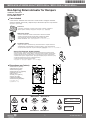
M9308-AGA-xZ / M9308-AUA-xZ / M9310-AUA-x / M9310-GUA-x / M9310-HGA-x
Non-Spring Return Actuator for Dampers
Part No. 34-636-2448 Rev. H
Issue Date March 2018
Installation Instructions
34-636-2448 Rev. H
1
346362448H
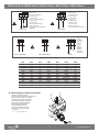
Parts Included
Instructions
M9300 Series Actuator
Anti-Rotation Bracket
IP54
MAX +60 °C +140 °F
MIN -30 °C -22 °F
MAX 95 % RH
LISTED 654U
TEMP REG EQUIP
CLASS 2
LISTED 654U
TEMP REG EQUIP
M93xx-xGx-xx
M93xx-xGx-xx
M93xx-xUx-xx
M93xx-xUx-xx
Dimensions mm (inches)
• Dimensions mm (pouces)
• Abmessungen mm (Zoll)
• Dimensioni mm (pollici)
• Dimensiones en mm (pulgadas)
• Afmetingen mm (inch)
• Mått mm (tum)
• Rozměry v mm (palcích)
• Wymiary mm (cale)
• Размеры мм (дюймы)
• Dimensões mm (polegadas)
•
尺寸毫米(英寸)
• 寸法 mm (インチ)
137
(5-13/32)
28
(1-3/32)
81
(3-3/16)
62
(2-7/16)
38
(1-1/2)
30
(1-3/16)
31
(1-7/32)
39
(1-17/32)
Special Tool Required: Digital Voltmeter
000
• Instructions • Anweisungen • Istruzioni • Instrucciones • Instructies • Instruktioner
• Návod k použití • Instrukcje • Инструкции • Instruções • 说明 • 使用説明書
• Pièces incluses • Enthaltene Teile • Parti incluse • Piezas incluidas • Inbegrepen onderdelen
• Delar som medföljer • Zahrnuté díly • Załączone części • Включенные детали • Peças incluídas
• 部件清单 • 含まれる部品
• Actionneur série M9300 • Antrieb der Serie M9300 • Attuatore Serie M9300
• Actuador serie M9300 • M9300-serie aandrijving • Ställdon Serie M9300
• Pohon řady M9300 • Siłownik serii M9300 • Привод серии M9300
• Atuador série M9300 • M9300 系列启动器 • M9300 シリーズアクチュエータ
• Outil spécial requis : Voltmètre numérique • Erforderliche Spezialwerkzeuge: Digitales Voltmeter
• Strumento speciale richiesto: Voltmetro digitale • Herramienta especial necesaria: voltímetro digital
• Benodigd speciaal gereedschap: Digitale voltmeter • Specialverktyg som krävs: Digital voltmeter
• Potřebné zvláštní vybavení: Digitální voltmetr • Wymagane narzędzie specjalne: Woltomierz cyfrowy
• Требуемый специальный инструмент: цифровой вольтметр
• Ferramenta especial necessária: Voltímetro digital
• 所需的特殊工具:数字电压表 • 必要特殊ツール:デジタル電圧計
• Support anti-rotation • Verdrehsicherung • Staffa anti-rotazione • Soporte antirrotación
• Antirotatiebeugel • Antirotationsfäste • Konzola proti otáčení • Uchwyt przeciwobrotowy
• Антиротационный кронштейн • Suporte antirrotação • 抗旋转支架 • アンチローテーションブラケット

34-636-2448 Rev. H
2
M9308-AGA-xZ / M9308-AUA-xZ / M9310-AUA-x / M9310-GUA-x / M9310-HGA-x
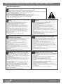
Important (USA, CANADA)
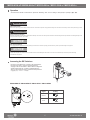
Mounting the Actuator
• Montage de l’actionneur • Montage des Antriebs • Montaggio dell’attuatore • Montaje del actuador • Aandrijving monteren
• Montering av ställdonet • Montáž pohonu • Montaż siłownika • Монтаж привода • Montagem do atuador • 安装启动器 • アクチュエータの取り付け
Use this M9300 Series Electric Non-Spring Return Actuator only to control equipment under normal operating conditions. Where failure or
malfunction of the electric actuator could lead to personal injury or property damage to the controlled equipment or other property, additional
precautions must be designed into the control system. Incorporate and maintain other devices, such as supervisory or alarm systems or safety or
limit controls, intended to warn of or protect against failure or malfunction of the electric actuator.
Utiliser ce M9300 Series Electric Non-Spring Return Actuator uniquement pour commander des équipements dans des conditions normales
de fonctionnement. Lorsqu’une défaillance ou un dysfonctionnement du electric actuator risque de provoquer des blessures ou d’endommager
l’équipement contrôlé ou un autre équipement, la conception du système de contrôle doit intégrer des dispositifs de protection supplémentaires.
Veiller dans ce cas à intégrer de façon permanente d’autres dispositifs, tels que des systèmes de supervision ou d’alarme, ou des dispositifs de
sécurité ou de limitation, ayant une fonction d’avertissement ou de protection en cas de défaillance ou de dysfonctionnement du electric actuator.
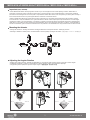
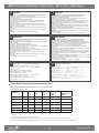
5
2
1
4
15°
15°
80°
5°
0% = 0° 100% = 95°
3
6
80°
5°
0% = 15° 100% = 95°
Adjusting the Angular Rotation
• Réglage de la rotation angulaire • Einstellen der Winkeldrehung • Regolazione della rotazione angolare • Ajuste de la rotación angular
• Hoekdraaiing aanpassen • Justering av vinkelrotationen • Seřízení úhlového otáčení • Regulacja obrotu kątowego
• Регулировка углового вращения • Ajuste da rotação angular • 调整角度旋转 • 角度回転の調整

34-636-2448 Rev. H
3
M9308-AGA-xZ / M9308-AUA-xZ / M9310-AUA-x / M9310-GUA-x / M9310-HGA-x
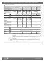
Shaft Diameter, mm (in.)
• Diamètre de l’arbre, mm (po) • Wellendurchmesser, mm (in.)
• Diametro albero, mm (poll.) • Diámetro del eje, mm (pulg.)
• Asdiameter, mm (inch) • Axeldiameter, mm (tum)
• Průměr hřídele, mm (palce) • Średnica wału, mm (cale)
• Диаметр вала, мм (дюймы) • Diâmetro do veio, mm (pol.)
• 轴直径,毫米(英寸)• シャフト直径 mm (インチ)
With Insert
• Avec insert • Mit Einsatz • Con inserto
• Con pieza intercalada • Met inzetstuk • Med insats
• S vložkou • Z wkładką • С вставкой
• Com inserto • 带插片 • イン サ ートあり
Without Insert
• Sans insert • Ohne Einsatz • Senza inserto
• Sin pieza intercalada • Zonder inzetstuk
• Utan insats • Bez vložky • Bez wkładki
• Без вставки • Sem inserto
• 不带插片 • インサートなし
9.5 (3/8) 12.7 (1/2) 16 (5/8) 19 (3/4)
8 (5/16) 10 (13/32) 12.7 (1/2) 16 (5/8)
Required Torque, lb-in. (N-m)
• Couple de serrage requis, N-m (lb-po) • Erforderliches Drehmoment, lb-in. (Nm)
• Coppia richiesta, lb-in. (N-m) • Par necesario, lb-pulg. (N-m)
• Vereist koppel, lb-inch (N-m) • Erforderligt vridmoment, lb-in. (N-m)
• Požadovaný moment, lb-in. (Nm) • Wymagany moment obrotowy, lb-in (N-m)
• Требуемый крутящий момент, фунт-дюйм (Н·м) • Binário necessário, lb-in.
(N-m) • 所需的扭矩,lb-in. (N-m) • 必要トルク lb-インチ (N-m)
125 (14.1)
Half-Turn Past Hand-Tighten
• Serrage à la main d’un demi-tour supplémentaire • Halbdrehung über handfest hinaus
• Mezzo giro oltre il serraggio manuale • Media vuelta de apriete manual
• Halve slag voorbij handvast • Halvt varv förbi åtdragning för hand
• Ručně utáhnout o více než půl otáčky • Pół obrotu ponad dokręcenie ręczne
• Пол-оборота после затяжки от руки • Meia volta apertada à mão
• 用手拧紧之后再旋转半圈 • 1/2回転で手締め
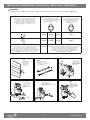
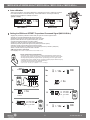
Installation
• Installation • Einbau • Installazione • Instalación • Installatie • Installation • Instalace • Instalacja • Установка • Instalação • 安装 • 据え付け
1
2
3
4
5
7
6
8
10
9
Attach
• Fixer • Anbringen
• Applicare • Conexión
• Bevestigen • Montera
• Připevnit • Przyczepienie
• Прикрепить • Juntar
• 连接 • 取り付け
Close
• Fermer • Schließen
• Chiudere • Cierre
• Sluiten • Stäng
• Zavřít • Zamknięcie
• Закрыть • Fechar
• 关闭 • 閉じる
Fasten
• Serrer • Befestigen • Fissare
• Sujeción • Aanhalen • Fäst
• Utáhnout • Przymocowanie • Зафиксировать
• Apertar • 旋紧 • 締め付け
Verify
• Vérier • Überprüfen
• Vericare • Vericación
• Controleren • Veriera
• Zkontrolovat • Potwierdzenie
• Проверить • Vericar
• 核验 • 確認
Place
• Placer • Platzieren
• Posizionare • Colocación
• Plaatsen • Placera
• Umístit • Ustawienie
• Разместить • Colocar
• 放置 • 設置
Adjust
• Régler • Einstellen • Regolare
• Ajuste • Aanpassen • Justera
• Seřídit • Regulacja • Отрегулировать
• Ajustar • 调整 • 調整

34-636-2448 Rev. H
4
M9308-AGA-xZ / M9308-AUA-xZ / M9310-AUA-x / M9310-GUA-x / M9310-HGA-x
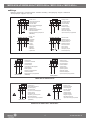
Wirings
• Câblages • Verdrahtungen • Collegamenti elettrici • Cableados • Bedrading • Ledningsdragning • Zapojení • Okablowanie
• Электропроводка • Ligações • 布线 • 配線
M9310-HGA-1 / M9310-HGA-2 / M9310-HGA-3
M9308-AGA-1Z / M9308-AGA-2Z
M9308-AUA-1Z / M9310-AUA-1 / M9310-AUA-3
•
On/Off Control
•
Commande marche/arrêt
•
Auf-/Zu-Regelung
•
Controllo On/Off
•
Control de encendido/apagado
•
Aan/uit-regeling
•
PÅ/AV-styrenhet
•
Regulace vypnutím/zapnutím
•
Sterowanie ON/OFF
•
Двухпозиционное регулирование
(ВКЛ/ВЫКЛ)
DC 0(2)...10 V
• Control
• Commande
• Regelung
• Controllo
• Control
• Regeling
• Styrenhet
• Regulace
• Sterowanie
• Управление
COM
(-)
2 31 4
RED GRYBLK ORN
(+)
0 to 10 VDC
(+)
0(2) to 10 VDC
24 V AC/DC
2 31 4
RED GRYBLK ORN
(-) COM
500 Ω
1.4 W
(+) 0 (4) to 20 mA
(+) 0 to 10 VDC
24 V AC/DC
•
Floating Control
•
Commande flottante
•
3-Punkt Regelung
•
Controllo flottante
•
Control flotante
•
Variabele regeling
•
Flytande styrenhet
•
Integrační regulace
•
Sterowanie astatyczne
•
Трехпозиционное регулирование
•
External resistor
•
Résistance externe
•
Externen Widerstand
•
Resistenza esterna
•
Resistencia externa
•
Externe weerstand
•
Extern resistor
•
Externí rezistor
•
Zewnętrzny rezystor
•
Внешний резистор
2 31
4
RED GRYBLK
ORN
COM
(-)
(+)
0 to 10 VDC
24 V AC/DC
24 V AC/DC
DA DA
COM
(-)
2 31 4
RED GRYBLK ORN
(+)
0 to 10 VDC
24 V AC/DC
DA DA
BLK RED ORN
On/Off Control
2 31
COM
(-)
24 VAC/DC
DA DA DA DA
BLK RED ORN
2 31
Floating Control
COM
(-)
24 VAC/DC
•
On/Off Control
•
Commande marche/arrêt
•
Auf-/Zu-Regelung
•
Controllo On/Off
•
Control de encendido/apagado
•
Aan/uit-regeling
•
PÅ/AV-styrenhet
•
Regulace vypnutím/zapnutím
•
Sterowanie ON/OFF
•
Двухпозиционное регулирование
(ВКЛ/ВЫКЛ)
•
Floating Control
•
Commande flottante
•
3-Punkt Regelung
•
Controllo flottante
•
Control flotante
•
Variabele regeling
•
Flytande styrenhet
•
Integrační regulace
•
Sterowanie astatyczne
•
Трехпозиционное регулирование
BRNBLU BRNBLUORN
On/Off Control
2 31
COM
(-)
85...264 VAC
85...264 V AC
ORN
2 31
Floating Control
COM
(-)
•
On/Off Control
•
Commande marche/arrêt
•
Auf-/Zu-Regelung
•
Controllo On/Off
•
Control de encendido/apagado
•
Aan/uit-regeling
•
PÅ/AV-styrenhet
•
Regulace vypnutím/zapnutím
•
Sterowanie ON/OFF
•
Двухпозиционное регулирование
(ВКЛ/ВЫКЛ)
•
Floating Control
•
Commande flottante
•
3-Punkt Regelung
•
Controllo flottante
•
Control flotante
•
Variabele regeling
•
Flytande styrenhet
•
Integrační regulace
•
Sterowanie astatyczne
•
Трехпозиционное регулирование
DA DA DA DA

34-636-2448 Rev. H
5
M9308-AGA-xZ / M9308-AUA-xZ / M9310-AUA-x / M9310-GUA-x / M9310-HGA-x
M9308-AUA-2Z / M9310-AUA-2
M9310-GUA-1 / M9310-GUA-2
BLK WHT BLU BRN GRY ORN RED
black white blue brown grey orange red
noir blanc bleu marron gris orange rouge
schwarz weiß blau braun grau orange rot
nero bianca blu marrone grigio arancione rosso
negro blanco azul marrón gris naranja rojo
zwart wit blauw bruin grijs oranje rood
svart vit blå brun grå orange röd
černá bílý modrá hnědá šedá oranžová červená
czarny biały niebieski brązowy szary pomarańczowy czerwony
Черный белый синий Коричневый серый oранжевый Красный
preto branco azul marrom cinza laranja vermelho
黑 白色 蓝 褐 灰 橙 红
ブラック ホ ワイト ブルー ブラウン グレー オレンジ 赤
1
2
3
Removing the Conduit Connector
• Retrait du raccord de conduit
• Entfernen der Schutzschlauchverschraubung
• Rimozione del raccordo per canalina
• Extracción del conector de conducto
• Verbindingsstuk leiding verwijderen
• Borttagning av ledningskontakten
• Sejmutí potrubního konektoru
• Usunięcie złącza przewodu
• Извлечение кабельного ввода
• Remover o conector da conduta
• 取下接线管
• コンジットコネクタの 取り外し
BLKWHT BLKWHTORN
On/Off Control
2 31
COM
(-)
120 VAC
120 VAC
ORN
2 31
Floating Control
COM
(-)
•
On/Off Control
•
Commande marche/arrêt
•
Auf-/Zu-Regelung
•
Controllo On/Off
•
Control de encendido/apagado
•
Aan/uit-regeling
•
PÅ/AV-styrenhet
•
Regulace vypnutím/zapnutím
•
Sterowanie ON/OFF
•
Двухпозиционное регулирование
(ВКЛ/ВЫКЛ)
•
Floating Control
•
Commande flottante
•
3-Punkt Regelung
•
Controllo flottante
•
Control flotante
•
Variabele regeling
•
Flytande styrenhet
•
Integrační regulace
•
Sterowanie astatyczne
•
Трехпозиционное регулирование
DA DA DA DA
COM(-)
35 4
GRYBLK ORN
(+)
0 to 10 VDC
(+)
0(2) to 10 VDC
DC 0(2)...10 V
• Control
• Commande
• Regelung
• Controllo
• Control
• Regeling
• Styrenhet
• Regulace
• Sterowanie
• Управление
Cable 2
Cable 1 M9310-GUA-2Cable 1 M9310-GUA-1
COM(-)
21
BLKWHT
(+)
85...264 VAC
COM(-)
21
BRNBLU
(+)
85...264 VAC

34-636-2448 Rev. H
6
M9308-AGA-xZ / M9308-AUA-xZ / M9310-AUA-x / M9310-GUA-x / M9310-HGA-x
Command
Signal Setting
Reverse
DA Not
used
Not
used
RA
LED
Direct
DA Not
used
RA
LED
Not
used
M9308-AGA-1Z / M9308-AUA-1Z / M9310-AUA-1 / M9310-AUA-3
DA Not
used
Not
used
RA
LED
Risque de décharge électrique.
Débrancher l'alimentation avant de réaliser tout branchement électrique. Tout contact avec des composants conducteurs de tensions dangereuses risque d'entraîner une décharge électrique et de
provoquer des blessures graves, voire mortelles.
Risk of Electric Shock.
Disconnect the power supply before making electrical connections. Contact with components carrying hazardous voltage can cause electric shock and may result in severe personal injury or death.
Risk of Property Damage.
Do not apply power to the system before checking all wiring connections. Short circuited or improperly connected wires may result in permanent damage to the equipment.
Risque de dégâts matériels.
Ne pas mettre le système sous tension avant d’avoir vérié tous les raccords de câblage. Des ls formant un court-circuit ou connectés de façon incorrecte risquent d’endommager
irrémédiablement l’équipement.
USA, CANADA:
WARNING
!
ADVERTISSEMENT
!
NOTICE
NOTICE
Accessing the DIP Switches
• Accès aux commutateurs DIP • Zugang zu den DIP-Schaltern
• Accesso ai DIP switch • Acceso a los interruptores DIP
• Toegang tot de DIP-schakelaars • Åtkomst till DIP-omkopplarna
• Přístup k přepínačům DIP • Dojście do przełączników DIP
• Доступ к DIP-переключателям • Aceder aos interruptores DIP
• 设置拨码开关 • DIPスイッチの作業
Operation
• Fonctionnement • Betrieb • Funzionamento • Operación • Bediening • Drift • Provoz • Obsługa • Эксплуатация • Operação • 操作 • 操作

34-636-2448 Rev. H
7
M9308-AGA-xZ / M9308-AUA-xZ / M9310-AUA-x / M9310-GUA-x / M9310-HGA-x
M9310-HGA-1 / M9310-HGA-3
Span Adj.
Offset Adj.
INC. DA 0-10
RA 2-10
Enter/
Autocal
LED
LED
LED
DIP Switches Settings
Example Command
Signal
Feedback
Signal
Setting User
Interface
1 0 - 10 VDC
Direct
0 - 10 VDC
DA 0-10
RA 2-10
10V
0V 5V 12V
Set Point
MAX
MIN
Stroke
2 0 - 10 VDC
Reverse
0 - 10 VDC
DA 0-10
RA 2-10
MAX
10V
MIN
0V 5V 12V
Stroke
Set Point
3 2 - 10 VDC
Direct
2 - 10 VDC
DA 0-10
RA 2-10
10V
0V 2V 5V 12V
Set Point
MAX
MIN
Stroke
4*
Offset = 5
Reverse
2 - 10 VDC
Span = 7
* see: Setting the SPAN and OFFSET Proportional Command Signal
M9310-GUA-1 / M9310-GUA-2
DA 0 -10
RA 2-10
Enter/
Autocal
DIP Switches Settings
Example Command
Signal
Feedback
Signal
Setting User
Interface
1 0 - 10 VDC
Direct
0 - 10 VDC
10V
0V 5V 12V
Set Point
MAX
MIN
Stroke
2 0 - 10 VDC
Reverse
0 - 10 VDC
MAX
10V
MIN
0V 5V 12V
Stroke
Set Point
3 2 - 10 VDC
Direct
2 - 10 VDC
10V
0V 2V 5V 12V
Set Point
MAX
MIN
Stroke
4 2-10 VDC
Reverse
2 - 10 VDC
10V
0V 2V 5V 12V
Set Point
MAX
MIN
Stroke
DA 0-10
RA 2-10
DA 0-10
RA 2-10
DA 0-10
RA 2-10
10V
0V 2V 5V 12V
Set Point
MAX
MIN
Stroke
DA 0-10
RA 2-10
DA 0-10
RA 2-10

34-636-2448 Rev. H
8
M9308-AGA-xZ / M9308-AUA-xZ / M9310-AUA-x / M9310-GUA-x / M9310-HGA-x
LED
LED
LED
INC.
ENTER/
AUTOCAL
LED
LED
LED
1.
2.
3.
4.
5a.
5b.
6.
7.
000
COM
(-)
2 31 4
RED GRYBLK ORN
(+)
0 to 10 VDC
(+)
0(2) to 10 VDC
24 V AC/DC
ENTER/
AUTOCAL
< 3s
ENTER/
AUTOCAL
< 3s
OFFSET
INC.
1x
2x
3x
+0.5 VDC
+1.0 VDC
+1.5 VDC
...
...
...
SPAN
OFFSET
LED
LED
LED
SPAN
INC.
1x
2x
3x
+0.5 VDC
+1.0 VDC
+1.5 VDC
...
...
...
or
LED
LED
LED
> 10s
OK
LED
LED
LED
> 10s
OK
Special Tool Required: Digital Voltmeter
000
• Outil spécial requis : Voltmètre numérique • Erforderliche Spezialwerkzeuge: Digitales Voltmeter
• Strumento speciale richiesto: Voltmetro digitale • Herramienta especial necesaria: voltímetro digital
• Benodigd speciaal gereedschap: Digitale voltmeter • Specialverktyg som krävs: Digital voltmeter
• Potřebné zvláštní vybavení: Digitální voltmetr • Wymagane narzędzie specjalne: Woltomierz cyfrowy
• Требуемый специальный инструмент: цифровой вольтметр
• Ferramenta especial necessária: Voltímetro digital
• 需要专用仪表:数字式电压表 • 必要特殊ツール:デジタル電圧計
Setting the SPAN and OFFSET Proportional Command Signal (M9310-HGA-x)
• Réglage des paramètres (PORTÉE ET DÉCALAGE) du signal de commande proportionnelle
• Einstellen der Proportional-Befehlssignale SPAN und OFFSET
• Regolazione dei segnali di comando proporzionali SPAN e OFFSET
• Ajuste de señales de instrucción proporcionales SPAN y OFFSET
• Proportioneel regelsignaal SPAN en OFFSET instellen
• Inställning av SPAN och OFFSET proportionell kommandosignal
• Nastavení poměrného příkazového signálu SPAN (Rozsah) a OFFSET (Posun)
• Ustawienie sygnału proporcjonalnego poleceń SPAN i OFFSET
• Установка пропорционального командного сигнала SPAN (диапазон) и OFFSET (смещение)
• Denir o sinal de comando proporcional SPAN e OFFSET
• 设置 SPAN 和 OFFSET 比例命令信号
• スパンの設定およびプロポーショナルコマンドシグナルのオフセット
Auto calibration
• Étalonnage automatique • Automatische Kalibrierung • Calibrazione automatica • Calibración automática
• Automatische kalibratie • Automatisk kalibrering • Automatická kalibrace • Automatyczna kalibracja
• Автоматическая калибровка • Calibração automática
• 自动校准 • 自動調整
INC.
ENTER/
AUTOCAL
LED
LED
LED
> 3s
RA
DA
2-10
0-10
ENTER/
AUTOCAL
> 3s
RA
DA
2-10
0-10
Min Max
M9310-HGA-x M9310-GUA-x

34-636-2448 Rev. H
9
M9308-AGA-xZ / M9308-AUA-xZ / M9310-AUA-x / M9310-GUA-x / M9310-HGA-x
• READ THIS INSTRUCTION SHEET AND THE SAFETY WARNINGS CAREFULLY BEFORE INSTALLING AND SAVE IT FOR FUTURE USE
• All wiring should conform to local codes and must be carried out by authorized personnel only.
• Keep high and low voltage wiring separated.
• When using multi-stranded wire, apply a cable ferrule to the cable end.
• Make sure that the line power supply is in accordance with the power supply specied on the device.
• Check all wiring connections before applying power to the system.
• Contact with components carrying hazardous voltage can cause electric shock and may result in severe injury or death.
• Short-circuited or improperly connected wires may result in permanent damage to the equipment.
• Not adhering to these operational instructions could cause injury or damage the equipment.
• This document is subject to change without notice.
INSTALLATION INSTRUCTIONS FOR THE TECHNICIAN / FITTER
en
• LISEZ ATTENTIVEMENT LES PRÉSENTES INSTRUCTIONS ET LES
CONSIGNES DE SÉCURITÉ AVANT DE PROCÉDER À L’INSTALLATION
ET CONSERVEZ LES AUX FINS D’UTILISATION ULTÉRIEURE
• Le raccordement électrique doit être réalisé par le personnel autorisé
conformément aux prescriptions locales.
• La tension d’alimentation et la basse tension doivent être amenées séparément.
• En cas d’utilisation de câbles exibles, il faut utiliser des cosses de câble.
• Assurez-vous que la tension d’alimentation coïncide avec les valeurs indiquées
sur le vérin.
• Contrôlez toutes les liaisons par câble avant de mettre le vérin en circuit.
• Le contact avec des composants porteurs de tensions dangereuses peut causer
une décharge électrique et peut entraîner des blessures graves ou la mort.
• Des ls en court-circuit ou mal branchés peuvent entraîner des dommages
permanents pour l’équipement.
• Ne pas respecter le présent mode d’emploi peut provoquer des blessures ou
endommager le matériel.
• Ce document peut être sujet à des modications sans préavis.
MANUEL D’INSTALLATION POUR LE SPECIALISTE /
MONTEU
fr
• LESEN SIE DIESE ANLEITUNG UND DIE SICHERHEITSHINWEISE VOR DER
INSTALLATION SORGFÄLTIG DURCH UND BEWAHREN SIE
SIE FÜR SPÄTERE REFERENZZWECKE AUF
• Der elektrische Anschluß ist nach den örtlichen Vorschriften durch autorisiertes
Personal durchzuführen.
• Versorgungsspannung und Niederspannung sind getrennt zuzuführen.
• Bei Verwendung von exiblen Leitungen sind Kabelschuhe zu verwenden.
• Stellen Sie sicher das die Versorgungsspannung mit dem angegebenen Wert des
Antriebes übereinstimmt.
• Überprüfen Sie alle Kabelverbindungen bevor Sie den Antrieb einschalten.
• Der Kontakt mit Komponenten, auf denen gefährliche Spannung anliegt, kann zu
einem Stromschlag führen und schwere Körperschäden oder sogar den Tod zur Folge
haben.
• Kurzgeschlossene oder falsch angeschlossene Drähte können bleibende Schäden am
Gerät verursachen.
• Die Missachtung dieser Bedienungsanleitung könnte zu Verletzungen oder zu
Beschädigungen des Equipments führen.
• Änderungen ohne Ankündigung vorbehalten.
INSTALLATIONSANLEITUNG FÜR DIE FACHKRAFT /
MONTEUR
de
• LEGGERE ATTENTAMENTE QUESTE ISTRUZIONI E LE AVVERTENZE PRIMA
DELL’INSTALLAZIONE E CONSERVARLE PER USO FUTURO
• L’allacciamento elettrico deve essere eseguito da personale autorizzato e
conformemente alle normative locali.
• La tensione di alimentazione e la bassa tensione devono essere alimentate
separatamente.
• In caso di impiego di conduttori essibili usare degli ancoraggi per cavi.
• Assicurarsi che il valore della tensione di alimentazione corrisponda a quello
prestabilito dell’attuatore.
• Prima di inserire l’azionamento controlare tutti gli allacciamenti dei cavi.
• Il contatto con componenti sottoposti a tensioni pericolose può causare scosse
elettriche con conseguenti lesioni gravi o morte.
• I cavi in corto circuito o collegati impropriamente potrebbero causare danni
permanenti all’apparecchiatura.
• Non attenersi alla presente istruzione operativa potrebbe causare danni alle persone
o alle attrezzature.
• Questo documento è soggetto a modiche senza preavviso
ISTRUZIONI D’INSTALLAZIONE PER IL
PERSONALE SPECIALIZZATO
it
• ANTES DE LA INSTALACIÓN, LEA ATENTAMENTE ESTAS INSTRUCCIONES Y LAS
ADVERTENCIAS DE SEGURIDAD,Y CONSÉRVELAS PARA SU USO FUTURO
• La conexión eléctrica deberá ser realizada según las disposiciones locales y por
personal autorizado.
• La tensión de alimentación y la baja tensión deben tenderse por separado.
• Al usar cables exibles, deberán utilizarse terminales de cable.
• Asegurar que la tensión de alimentación coincida con el valor indicado para el
accionamiento.
• Comprobar todas las conexiones de cables, antes de conectar el accionamiento.
• El contacto con elementos portadores de alto voltaje puede provocar una descarga
eléctrica y producir lesiones graves o incluso la muerte.
• Los cables cortocircuitados o mal conectados pueden provocar daños permanentes en
el equipo.
• El incumplimiento de estas instrucciones de funcionamiento puede causar lesiones
personales o daños en el equipo.
• Este documento está sujeto a cambios sin previo aviso.
INSTRUCCIONES TÉCNICAS DE INSTALACIÓN
es
International Warnings
• LÄS DET HÄR INSTRUKTIONSBLADET OCH SÄKERHETSANVISNINGARNA
NOGGRANT INNAN DU INSTALLERAR MODULEN OCH SPARA DEM FÖR
FRAMTIDA BRUK
• Elanslutningen ska utföras av behörig personal i enlighet med de lokala
föreskrifterna.
• Försörjningsspänning och lågspänning ska tillföras åtskilt.
• Vid användning av exibla ledningar ska kabelskor användas.
• Säkerställ att försörjningsspänningen stämmer överens med det angivna värdet
för ställdonet.
• Kontrollera alla kabelförbindelser innan du tillkopplar ställdonet.
• Kontakt med komponenter med farlig spänning kan ge elektriska stötar som kan
orsaka allvarliga eller livshotande personskador.
• Kortslutna eller felaktigt anslutna kablar kan resultera i varaktiga skador på
utrustningen.
• Om innehållet i den här bruksanvisningen inte efterföljs kan det leda till skada på
person eller utrustning.
• Det här dokumentet kan ändras utan föregående meddelande.
INSTALLATIONSGUIDE FÖR INSTALLATÖR /
MONTÖR
se
• LEES DIT INSTRUCTIEBLAD EN DE VEILIGHEIDSWAARSCHUWINGEN
ZORGVULDIG VOORDAT DE INSTALLATIE WORDT UITGEVOERD,
EN BEWAAR DIT MATERIAAL ZODAT U HET IN DE TOEKOMST OOK NOG
KUNT RAADPLEGEN
• De elektrische aansluiting moet volgens de plaatselijke voorschriften door
geautoriseerd personeel uitgevoerd worden.
• Voedingsspanning en laagspanning moeten afzonderlijk toegevoerd worden.
• Bij het gebruik van exibele leidingen moeten kabelschoenen gebruikt
worden.
• Zorg ervoor dat de voedingsspanning met de opgegeven waarde van de
aandrijving overeenstemt.
• Controleer alle kabelverbindingen voor u de aandrijving inschakelt.
• Contact met onderdelen met een gevaarlijke spanning kan elektrische
schokken veroorzaken en ernstig letsel of de dood tot gevolg hebben.
• Kortsluitingen of verkeerd aangesloten bedradingen kunnen permanente
schade aan de apparatuur tot gevolg hebben.
• Het niet naleven van deze gebruiksinstructies kan leiden tot persoonlijk letsel
of schade aan de apparatuur.
• Dit document kan zonder kennisgeving worden gewijzigd.
INSTALLATIEHANDLEIDING VOOR DE VAKMAN /
MONTEUR
nl

34-636-2448 Rev. H
10
M9308-AGA-xZ / M9308-AUA-xZ / M9310-AUA-x / M9310-GUA-x / M9310-HGA-x
• PŘED INSTALACÍ SI POZORNĚ PŘEČTĚTE TYTO POKYNY A BEZPEČNOSTNÍ
VAROVÁNÍ A USCHOVEJTE JE PRO POZDĚJŠÍ POUŽITÍ
• Veškerá zapojení by měla odpovídat místním předpisům a musí být prováděna pouze
oprávněnými pracovníky.
• Vysokonapěťová a nízkonapěťová vedení oddělte.
• Pri použití vícežilového kabelu instalujte do pruchodky gumový tesnicí kroužek.
• Zkontrolujte, zda síťový zdroj odpovídá požadovanému zdroji napájení, který je
uveden na zařízení.
• Před připojením systému ke zdroji napájení proveďte kontrolu všech zapojení.
• Kontakt se součástmi, které jsou pod napětím, může způsobit zasažení elektrickým
proudem a vážný úraz nebo smrt.
• Zkratované nebo nesprávně připojené vodiče mohou způsobit nevratné poškození
zařízení.
• Nedodržení těchto provozních pokynů by mohlo způsobit zranění nebo poškození
zařízení.
• Tento dokument podléhá změnám bez předchozího upozornění.
POKYNY K INSTALACI PRO TECHNIKY A
MONTÉRY
cz
• PRZED INSTALACJĄ NALEŻY UWAŻNIE PRZECZYTAĆ TĘ INSTRUKCJĘ I
OSTRZEŻENIA DOTYCZĄCE BEZPIECZEŃSTWA ORAZ ZACHOWAĆ
JE W CELU PÓŹNIEJSZEGO UŻYCIA
• Okablowanie musi być zgodne z lokalnymi przepisami i jego montaż musi być
przeprowadzany wyłącznie przez uprawniony personel.
• Należy odseparować kable niskiego napięcia od okablowania wysokiego napięcia.
• W przypadku stosowania kabla wielożyłowego należy założyć tulejkę na jego koniec.
• Należy upewnić się, że źródło zasilania jest zgodne z parametrami zasilania
określonymi na urządzeniu.
• Przed włączeniem zasilania systemu należy sprawdzić wszystkie połączenia kabli.
• Dotknięcie elementów będących pod niebezpiecznym napięciem może spowodować
porażenie i poważne obrażenia lub nawet śmierć.
• Zwarcia lub nieprawidłowo podłączone kable mogą spowodować trwałe uszkodzenie
urządzeń.
• Nieprzestrzeganie niniejszych instrukcji użytkowania może spowodować obrażenia lub
uszkodzenie sprzętu.
• Informacje zawarte w tym dokumencie mogą ulec zmianie bez powiadomienia.
INSTRUKCJA INSTALACJI DLA TECHNIKA/
MONTERA
pl
ИНСТРУКЦИЯ ПО УСТАНОВКЕ ДЛЯ ТЕХНИКА/
МОНТАЖНИКА
ru
• ПЕРЕД УСТАНОВКОЙ ВНИМАТЕЛЬНО ПРОЧИТАЙТЕ НАСТОЯЩУЮ
ИНСТРУКЦИЮ И УКАЗАНИЯ ПО ОБЕСПЕЧЕНИЮ БЕЗОПАСНОСТИ,
СОХРАНИТЕ ЭТУ ИНСТРУКЦИЮ ДЛЯ ПОСЛЕДУЮЩЕГО ИСПОЛЬЗОВАНИЯ
• Все электрические цепи и соединения должны соответствовать местным нормам и
правилам и должны выполняться только уполномоченным персоналом.
• Прокладывайте цепи высокого и низкого напряжения отдельно.
• В случае применения много жильного провода заключите конец провода в
наконечник.
• Удостоверьтесь в том, что напряжение питающей сети соответствует напряжению
питания, которое указано на корпусе устройства.
• Проверьте все проводные соединения, прежде чем подавать питание на систему.
• Прикосновение к частям и элементам, находящимся под опасным напряжением,
может привести к серьезному увечью или смерти в результате поражения
электротоком.
• Короткое замыкание или неправильное подключение электрических цепей может
привести к неустранимому повреждению оборудования.
• Несоблюдение настоящих указаний может стать причиной несчастного случая или
повреждения оборудования.
• Настоящий документ может быть изменен без уведомления.
• LEIA ESTE FOLHA DE INSTRUÇÕES E OS AVISOS DE SEGURANÇA ANTES DE
INSTALAR E GUARDAR PARA USO FUTURO
• Toda a ação eletrica devera ser realizadas segundo a disposicão locais e apenas por
pessoal autorizado
• Manter os os de alta tensão e baixa separados.
• Ao usar o exivel aplicar na extremidade do cabo terminais.
• Certique-se que o fornecimento de energia da linha está de acordo com a fonte de
alimentação especicada no dispositivo.
• Verique todas as ligações antes de ligar para o sistema.
• Contato com os componentes portadores de alte tensão pode provocar choque elétrico
e podem resultar ferimentos graves ou morte.
• Curto-circuito ou os mal conectados podem provocar danos permanentes no
equipamento.
• Não aderir a estas instruções operacionais pode provocar ferimentos ou danos ao
equipamento.
• Este documento está sujeito a alterações, sem aviso prévio.
INSTRUÇÕES DE INSTALAÇÃO PARA O TÉCNICO/
INSTALADOR
pt
• 安装前请仔细阅读安装说明书和安全警示,并保留以备将来使用
• 所有接线必须符合当地电器规范,并由具有资质的人员进行接线
• 将高压和低压线分离
• 当使用多股线时,请在电缆末端安装金属套圈
• 确保所接的电源规格符合产品所规定的电源要求
• 系统通电前检查所有接线是否准确
• 触碰带有危险电压的部件可能引起触电,并可导致人员受伤或死亡
• 短路或者错误接线会导致设备永久性损坏
• 不遵守这些操作指南会导致人员受伤或者机器损坏
• 本文档如有变化,恕不另行通知
• 使用するためのご注意
• 配線作業の感電を防止するため、結線前に、供給元の電源を切ってください。
• 配線を電源配線や電圧の発生する他の配線と同一の配線に収納しないでください。
• 供給電源が本装置に指定されているは電源通りであることを確認してください。
• 電源を供給する前に、必ずすべての結線を確認してください。
• 配線・結線作業は電源を切った状態で行ってください。感電することがあります。
• 短絡や不適切な配線は修復不可能なダメージを機器に与えることがあります。
• 当社サービスマン、もしくは認定された人以外、機器内部に触れないでください。
• 製品の誤用や不正使用によって起因する損害については、一切責任を負いかねます。
• 記載内容はお断りなく変更することがありますのでご了承ください。
适用于技术人员与安装人员的安装说明书
一般仕様・取扱説明書
cn jp
Part Name
1
Lead
(Pb)
Mercury
(Hg)
Cadmium
(Cd)
Hexavalent
chronium
(CrVI)
Polybrominated
biphenyls
(PBB)
Polybrominated
biphenyl ethers
(PBDE)
Electronics o o o o o o
Motor
2
o o o o o o
Gearbox
2
o o o o o o
Accessory (metallic
removable parts)
x o o o o o
Valve, flow unit x o o o o o
Valve, body x o o o o o
China RoHS Hazardous Substances Declaration
Actuator-valve combinations: Electric actuator and linkage, globe valve or rotary valve.
Valve: Valve body, flange, flow unit.
1
Note that some of the listed parts may not be parts of the enclosed product.
2
Actuators only.
This table is prepared in accordance with the provisions of SJ/T 11364.
o: Indicates that said hazardous substance contained in all of the homogeneous materials for this part is below the limit requirements of GB/T 26572.
x: Indicates that said hazardous substance contained in at least one of the homogeneous materials used for this part is above the limit requirements of GB/T 26572.

34-636-2448 Rev. H
11
M9308-AGA-xZ / M9308-AUA-xZ / M9310-AUA-x / M9310-GUA-x / M9310-HGA-x
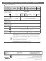
Technical Specications
Product Code
• Code produit • Produktcode
• Codice prodotto • Código de producto
• Productcode • Produktkod • Kód výrobku
• Kod produktu • Код продукта
• Código de produto • 产品代码 • 製 品コ ード
M9310-HGA-1 M9310-HGA-3 M9310-GUA-1 M9310-GUA-2
Control Type
• Type de commande • Steuerungsart
• Tipo di comando • Tipo de control
• Besturingstype • Kontrolltyp • Typ řízení
• Typ sterowania • Тип управления
• Tipo de controlo • 控制类型 • 制御タイプ
On/Off,
Floating
Proportional
On/Off,
Floating
Proportional Proportional
Power
24 V ±20%, 50/60 Hz. 6.2 VA
24 VDC ±10%, 1.9 W
24 V ±20%, 50/60 Hz. 4.7 VA
24 VDC ±10%, 1.3 W
Nominal AC 230V
at 50/60 Hz: 0.05 A
Running
Nominal AC 120V
at 60 Hz: 0.05 A
Running
Transformer
≥6.5 VA —
Input
• Entrée • Eingang • Ingresso • Entrada
• Ingang • Ingång • Vstup • Wejście
• Вход • Entrada • 输入 • 入力
24 VAC ±20%,
24 VDC ±10%
0(2)...10 VDC,
0(4)...20 mA with
field furnished 500
ohm resistor
Offset: 0...10 VDC
Span: 2...10 VDC
24 VAC ±20%,
24 VDC ±10%
0(2)...10 VDC,
0(4)...20 mA with
field furnished 500
ohm resistor
Offset: 0...10 VDC
Span: 2...10 VDC
AC 100...240 V (AC 85...264 V) at 50/60
Hz
Impedance
• Impédance • Impedanz • Impedenza
• Impedancia • Impedantie • Impedans
• Impedance • Impedancja • Импеданс
• Impedância • 阻抗 • インピーダンス
4.7k ohm 100k ohm 4.7k ohm 100k ohm 100k ohm
Feedback
• Rétroaction • Rückmeldung • Ritorno
• Realimentación • Feedback • Feedback
• Zpětná vazba • Sprzężenie zwrotne
• Обратная связь • Feedback • 反馈
• フィードバック
— 0(2)...10 VDC — 0(2)...10 VDC 0(2)...10 VDC
Torque
10 Nm (90 lb.in)
Rotation
Range
Mechanically Limited 35° to 95° ±3° in 5° increments
Rotation
Time
35 s 90 s 35 s 90 s
Compliance
United States: UL Listed, CCN XAPX, File E27734; to UL 60730-1: Automatic Electrical Controls for Household and
Similar Use, Part 1; and UL 60730-2-14: Part 2, Particular Requirements for Electric Actuators. Plenum Rated (UL
2043). Suitable for use in Other Environmental Air Space (Plenum) in accordance with section 300.22 (c) of the National
Electrical Code.
Canada: UL Listed, CCN XAPX7, File E27734; to CAN/CSA E60730-1:02: Automatic Electrical Controls for Household
and Similar Use, Part 1; and CAN/CSA-E60730-2-14, Particular Requirements for Electric Actuators.
Europe: CE Mark
Johnson Controls declares that these products are in compliance with the essential requirements and other relevant
provisions of the EMC Directive and Low Voltage Directive.
Australia and New Zealand: RCM Mark, Australia/NZ Emissions Compliant
M

European Single Point of Contact:
JOHNSON CONTROLS
WESTENDHOF 3
45143 ESSEN
GERMANY
NA/SA Single Point of Contact:
JOHNSON CONTROLS
507 E MICHIGAN ST
MILWAUKEE WI 53202
USA
APAC Single Point of Contact:
JOHNSON CONTROLS
C/O CONTROLS PRODUCT MANAGEMENT
NO. 22 BLOCK D NEW DISTRICT
WUXI JIANGSU PROVINCE 214142 - CHINA
www.johnsoncontrols.com
Building Technologies & Solutions
Headquarters: Milwaukee, Wisconsin, USA
Branch Officies: Principal Cities World-wide
Johnson Controls
®
is registered trademark of Johnson Controls.
All other marks herein are the marks of their respective owners.
© Copyright 2018 Johnson Controls. All rights reserved. Any unauthorized use or copying is strictly prohibited.
M9308-AGA-xZ / M9308-AUA-xZ / M9310-AUA-x / M9310-GUA-x / M9310-HGA-x
Technical Specications
Product Code
• Code produit • Produktcode
• Codice prodotto • Código de producto
• Productcode • Produktkod • Kód výrobku
• Kod produktu • Код продукта
• Código de produto • 产品代码 • 製 品コ ード
M9308-
AGA-1Z
M9308-
AGA-2Z
M9308-
AUA-1Z
M9308-
AUA-2Z
M9310-AUA-1 M9310-AUA-2 M9310-AUA-3
Control Type
• Type de commande • Steuerungsart
• Tipo di comando • Tipo de control
• Besturingstype • Kontrolltyp • Typ řízení
• Typ sterowania • Тип управления
• Tipo de controlo • 控制类型 • 制御タイプ
On/Off, Floating
Power
24 V ±20%, 50/60 Hz,
12.7 VA
24 VDC ±10%, 5.7 VA
Nominal AC
230V at 50/60
Hz: 0.08 A
Running
Nominal AC
120V at 60
Hz: 0.11 A
Running
Nominal AC 230V
at 50/60 Hz:
0.08 A Running
Nominal AC 120V
at 60 Hz:
0.04 A Running
Nominal AC 230V
at 50/60 Hz:
0.08 A Running
Transformer
≥13 VA —
Input
• Entrée • Eingang • Ingresso • Entrada
• Ingang • Ingång • Vstup • Wejście
• Вход • Entrada • 输入 • 入力
24 VAC ±20%,
24 VDC ±10%
AC 100...240 V (AC 85...264 V) at 50/60 Hz
Impedance
• Impédance • Impedanz • Impedenza
• Impedancia • Impedantie • Impedans
• Impedance • Impedancja • Импеданс
• Impedância • 阻抗 • インピーダンス
—
Feedback
• Rétroaction • Rückmeldung • Ritorno
• Realimentación • Feedback • Feedback
• Zpětná vazba • Sprzężenie zwrotne
• Обратная связь • Feedback • 反馈
• フィードバック
—
Torque
8 Nm (70 lb·in) 10 Nm (90 lb·in)
Rotation Range
Mechanically Limited 35° to 95° ±3° in 5° increments
Rotation Time
8s 35 s 90 s
Compliance
United States: UL Listed, CCN XAPX, File E27734; to UL 60730-1: Automatic Electrical Controls for Household
and Similar Use, Part 1; and UL 60730-2-14: Part 2, Particular Requirements for Electric Actuators. Plenum Rated
(UL 2043). Suitable for use in Other Environmental Air Space (Plenum) in accordance with section 300.22 (c) of the
National Electrical Code.
Canada: UL Listed, CCN XAPX7, File E27734; to CAN/CSA E60730-1:02: Automatic Electrical Controls for
Household and Similar Use, Part 1; and CAN/CSA-E60730-2-14, Particular Requirements for Electric Actuators.
Europe: CE Mark
Johnson Controls declares that these products are in compliance with the essential requirements and other relevant
provisions of the EMC Directive and Low Voltage Directive.
Australia and New Zealand: RCM Mark, Australia/NZ Emissions Compliant
M
-
 1
1
-
 2
2
-
 3
3
-
 4
4
-
 5
5
-
 6
6
-
 7
7
-
 8
8
-
 9
9
-
 10
10
-
 11
11
-
 12
12


Johnson Controls M9310-GUA series Installation Instructions Manual
- Taper
- Installation Instructions Manual
- Ce manuel convient également à
Documents connexes
Autres documents
-
ESBE ALFxx1 Mode d'emploi
-
Lindy 38131 Manuel utilisateur
-
-
ESAB 251 FABRICATOR® Mig Welding Machine Manuel utilisateur
-
Lincoln Electric CLASSIC I Mode d'emploi
-
-
-
-
-