United States Stove 1269E Le manuel du propriétaire
- Catégorie
- Poêle à bois
- Taper
- Le manuel du propriétaire

852430F-1203H
Owner’s Operation and Instruction Manual
SAFETY NOTICE:
If this heater is not properly installed, a house
re may result. For your safety, follow the
installation instructions. Never use make-shift
compromises during the installation of this
heater. Contact local building or re ofcials
about permits, restrictions and installation
requirements in your area.
CAUTION!
Please read this entire manual before you
install or use your new room heater. Failure
to follow instructions may result in property
damage, bodily injury, or even death.
Improper Installation Could Void
Your Warranty!
U.S. Environmental Protection Agency
Certied to comply with 2015 particulate
emission standards for single burn rate
heaters. Not approved for sale after May 15,
2020. This single burn rate wood heater is not
approved for use with a ue damper.
Certied To: UL 1482 and ULC 627
United States Stove Company
227 Industrial Park Road
South Pittsburg, TN 37380
DO NOT USE THIS HEATER IN A MOBILE HOME. SAVE THESE INSTRUCTIONS
THIS MANUAL WILL HELP YOU TO OBTAIN EFFICIENT, DEPENDABLE SERVICE FROM THE HEATER, AND ENABLE YOU
TO ORDER REPAIR PARTS CORRECTLY. KEEP IN A SAFE PLACE FOR FUTURE REFERENCE.
MODEL: 1269E Log Wood
CALIFORNIA PROPOSITION 65 WARNING:
This product can expose you to chemicals including carbon monoxide, which
is known to the State of California to cause cancer, birth defects and/or other
reproductive harm. For more information, go to www.P65warnings.ca.gov
Ce produit peut vous exposer à des produits chimiques, y compris le
monoxyde de carbone, qui est connu dans l'État de Californie pour causer
le cancer, des malformations congénitales et / ou d'autres problèmes de
reproduction. Pour plus d'informations, visitez www.P65warnings.ca.gov

-2-
This manual describes the installation and operation of the United States Stove
Company Model 1269E woodheater. This heater meets the 2015 U.S. Environmental
Protection Agency's crib wood emission limits for woodheaters sold after May 15, 2015.
Under specic EPA test conditions burning Douglas Fir dimensional lumber this heater
has been shown to deliver heat at a rate of 24,433 Btu/hr. This heater achieved a
particulate emissions rate of 4.2 g/hr when tested to method ASTM E2780-10 single Burn
Rate Appendix (*and an efciency of 67.9 %.)
This wood heater has a manufacturer-set minimum low burn rate that must not be altered. It is against federal
regulations to alter this setting or otherwise operate this wood heater in a manner inconsistent with operating
instructions in this manual.
The operation of this wood heater in a manner inconsistent with the owner’s manual will void you warranty and
is also against federal regulations.
This heater is designed to burn natural wood only. Higher efciencies and lower emissions generally result when
burning air dried seasoned hardwoods, as compared to softwoods or to green or freshly cut hardwoods. Burning
the following materials may result in release of toxic fumes or render the heater ineffective and cause smoke.
This wood heater needs periodic inspection and repair for proper operation. It is against federal regulations to
operate this wood heater in a manner inconsistent with operating instructions in this manual.
CONGRATULATIONS!
You’ve purchased a heater from North America’s oldest manufacturer of wood burning products.
By heating with wood you’re helping to CONSERVE ENERGY!
Wood is our only Renewable Energy Resource. Please do your part to preserve our wood supply. Plant at least
one tree each year. Future generations will thank you.
The instructions pertaining to the installation of your wood stove comply with UL & ULC standards.
Combustible: Wood
Colors: Flat Black
Flue Pipe Diameter: 6” (15.3cm)
Flue Pipe Type: (Standard Single Wall or Double Wall): Black or Blued Steel 2100°F (650°C)
Minimum Chimney Height: 12’ (3.7m)
Maximum Log Length: 22” (559mm)
Electrical: None
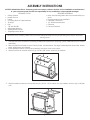
Dimensions
Overall ( Depth x Width x Height ): 33” x 18.5” x 23” (838mmX470mmX854mm)
Combustion Chamber: Width x Depth: 19” x 9” (482mmX229mm)
Volume: Cubic Feet: 1.2 cubic feet
Door Opening: 7.5 x 10.2 (191mmX259mm)
Pyroceramic Glass Door : (Viewing) Width x Height: N/A
Weight (lbs): 140 lbs
Report No. 0215WS038E
Note: Register your product on line at www.usstove.com. Save your receipt with your records for any claims.

-3-
33"
4-5/8"
23"
FLOOR PROTECTOR
11-3/8"
18-1/2"
26-1/2"
8"
DO NOT BURN:
1. Residential or commercial garbage;
2. Lawn clippings or yard waste;
3. Materials containing rubber, including tires;
4. Materials containing plastic;
5. Waste petroleum products, paints or paint thinners, or asphalt products;
6. Materials containing asbestos;
7. Construction or demolition debris;
8. Paper products, cardboard, plywood, or particleboard. The prohibition against burning these materials does
not prohibit the use of re starters made from paper, cardboard, saw dust, wax and similar substances for the
purpose of starting a re in unaffected wood heater.
9. Railroad ties or pressure-treated wood;
10. Manure or animal remains;
11. Salt water driftwood or other previously salt water saturated materials;
12. Unseasoned wood;
13. Any materials that are not included in the warranty and owner’s manual for the subject wood heater; or
14. Any materials that were not included in the certication tests for the subject wood heater.
Do not burn manufactured logs made of wax impregnated sawdust or logs with any
chemical additives. Manufactured logs made of 100% compressed sawdust can be
burned, but be careful burning too much of these logs at the same time. Start with one
manufactured log and see how the stove reacts. You can increase the number of logs
burned at a time to making sure the temperature never rises higher than 475 °F (246 °C)
on a magnetic thermometer for installation on single wall stove pipes or 900 °F (482 °C)
on a probe thermometer for installation on double wall stove pipe. The thermometer
should be placed about 18” (457 mm) above the stove. Higher temperatures can lead
to overheat and damage your stove.
Tools and Materials Needed
TOOLS
• Pencil
• 6 Foot Folding Ruler or Tape Measure
• Tin Snips
• Drill, Hand or Electric
• Drill Bit 1/8" Dia. (For Sheet Metal Screws)
• Adjustable Wrench
• Screw Driver (Blade-Type)
• Gloves
• Safety Glasses
MATERIALS
• 6" Elbow, Collar and Thimble; As Required (24 gauge
min.)
• 1/2" Sheet Metal Screws (No. 10A x 1/2")
• 6" Diameter, 24 gauge, black or blued steel ue
connector pipe
• Floor Protector Material (R value = 2.06); Size and
Installation as specied in this manual
• Furnace Cement (Manufacturer Recommends:
Rutland Black Code 78 or Equivalent)
• Optional; 6" Barometric Draft Regulator (DR-6)
HEATER DIMENSIONS FIG. 1

-4-
Operational Tips
BUILDING A FIRE
The top down method of re building is recommended for this appliance. Place the largest pieces of wood on
the bottom, laid in parallel and close together. Smaller pieces are placed in a second layer, crossways to the
rst. A third layer of still smaller pieces is laid crossways to the second, this time with some spaces between. Then
a fourth layer of loose, small kindling and twisted newspaper sheets tops off the pile.
VISIBLE SMOKE
Visible smoke is basically unburned fuel and moisture leaving your stove. The amount of visible smoke being
produced can be an effective method of determining how efciently the combustion process is taking place at
the given settings. Learn to adjust the air settings of your specic unit to produce the smallest amount of visible
smoke. Remember that wood that has not been seasoned properly and has a high wood moisture content will
produce excess visible smoke and burn poorly.
ASH REMOVAL AND DISPOSAL
Whenever ashes get 3 to 4 inches deep in your rebox or ash pan, and when the re has burned down and
cooled, remove excess ashes. Leave an ash bed approximately 1 inch deep on the rebox bottom to help
maintain a hot charcoal bed.
Ashes should be placed in a metal container with a tight-tting lid. The closed container of ashes should be
placed on a noncombustible oor or on the ground, away from all combustible materials, pending nal disposal.
The ashes should be retained in the closed container until all cinders have thoroughly cooled.
AIR TUBES
The air tubes assembled in this unit are designed to provide an accurate mix of secondary air to insure the
highest efciency. Any damage or deterioration of these tubes may reduce the efciency of combustion. The
air tubes are held in position by either screws or snap pins. Locate these to either side of the tube and remove to
allow the tube to be removed and replaced.
OVER FIRING
Attempts to achieve heat output rates that exceed heater design specications can result in permanent
damage to the heater and to the catalytic combustor if so equipped.
IMPORTANCE OF PROPER DRAFT
Draft is the force which moves air from the appliance up through the chimney. The amount of draft in your
chimney depends on the length of the chimney, local geography, nearby obstructions and other factors. Too
much draft may cause excessive temperatures in the appliance and may damage the catalytic combustor
(if equipped). Inadequate draft may cause backpufng into the room and ‘plugging’ of the chimney or the
catalyst (if equipped). Inadequate draft will cause the appliance to leak smoke into the room through appliance
and chimney connector joints. An uncontrollable burn or excessive temperature indicates excessive draft.
CHIMNEY
Take into account the chimney’s location to insure it is not too close to neighbors or in a valley which may cause
unhealthy or nuisance conditions.

-5-
EFFICIENCY
Efciencies can be based on either the lower heating value (LHV) or the higher heating value (HHV) of the fuel.
The lower heating value is when water leaves the combustion process as a vapor, in the case of woodstoves the
moisture in the wood being burned leaves the stove as a vapor. The higher heating value is when water leaves
the combustion process completely condensed. In the case of woodstoves this would assume the exhaust gases
are room temperature when leaving the system, and therefore calculations using this heating value consider
the heat going up the chimney as lost energy. Therefore, efciency calculated using the lower heating value of
wood will be higher than efciency calculated using the higher heating value. In the United States all woodstove
efciencies should be calculated using the higher heating value.
As an operator of a wood heater the best way to achieve optimum efciencies is to learn the burn characteristic
of you appliance and burn well-seasoned wood. A good rule of thumb is that your heater is not producing or
producing very little visible smoke it is burning efciently. Also remember that higher burn rates are not always
the best heating burn rates; after a good re is established a lower burn rate may be a better option for efcient
heating. A lower burn rate slows the ow of usable heat out of the home through the chimney, and it also
consumes less wood.
SMOKE AND CO MONITORS
Burning wood naturally produces smoke and carbon monoxide(CO) emissions. CO is a poisonous gas when
exposed to elevated concentrations for extended periods of time. While the modern combustion systems in
heaters drastically reduce the amount of CO emitted out the chimney, exposure to the gases in closed or
conned areas can be dangerous. Also make sure you stove gaskets and chimney joints are in good working
order and sealing properly to ensure unintended exposure. It is recommended that you use both smoke and CO
monitors in areas expected to or having the potential to generate CO.
OPERATIONAL TIPS FOR GOOD, EFFICIENT, AND CLEAN COMBUSTION
Use smaller pieces of wood during start-up and a high burn rate to increase the stove temperature
Be considerate of the environment and only burn dry wood
Burn small, intense res instead of large, slow burning res when possible
Learn your appliance's operating characteristics to obtain optimum performance
Burning unseasoned wet wood only hurts your stoves efciency and leads to accelerated creosote buildup in
your chimney
WOOD SELECTION TIPS
Dead wood lying on the forest oor should be considered wet, and requires full seasoning time. Standing dead
wood can usually be considered to be about 2/3 seasoned. Splitting and stacking wood before it is stored
accelerates drying time. Storing wood on an elevated surface from the ground and under a cover or covered
area from rain or snow also accelerates drying time. A good indicator if wood is ready to burn is to check the
piece ends. If there are cracks radiating in all directions from the center then the wood should be dry enough
to burn. If your wood sizzles in the re, even though the surface is dry, it may not be fully cured, and should be
seasoned longer.

-6-
Safety Rules
NOTE: FOR YOUR SAFETY, WE RECOMMEND INSTALLING SMOKE DETECTORS IN YOUR HOME IF NOT ALREADY
INSTALLED.
CAUTION! Do not touch the heater until it has cooled.
SAFETY NOTICE: If this heater is not properly installed, a house re may result. For your safety, follow the
installation directions. Contact local building or re ofcials about restrictions and installation inspection
requirements in your area.
READ THESE RULES AND THE INSTRUCTIONS CAREFULLY
1. Check with local codes. The installation must
comply with their rulings. Observe closely the
clearances to combustibles.
2. Do not install this heater in a mobile home or trailer.
3. Always connect this heater to a chimney and
vent to the outside. Never vent to another room or
inside a building. DO NOT CONNECT THIS UNIT TO A
CHIMNEY FLUE SERVING ANOTHER APPLIANCE.
4. Do not connect a wood burning heater to a Type
B gas vent. This is not safe and is prohibited by
the National Fire Protection Association Code.
This heater requires approved masonry or UL,
ULC Listed Residential Type and Building Heating
Appliance Chimney. Use a 6" diameter chimney,
or larger, that is high enough to give a good draft.
5. Be sure that your chimney is safely constructed and
in good repair. Have the chimney inspected by
the Fire Department or a qualied inspector. Your
insurance company may be able to recommend
a qualied inspector.
6. Inspect chimney connector and chimney twice
monthly during the heating season for any deposit
of creosote or soot which must be removed (see
Chimney Maintenance).
7. Provide air for combustion from outside the house
into the room where the heater is located. If the
intake is not in the same room, air must have free
access in to the room.
8. To prevent injury, do not allow anyone to use this
heater who is unfamiliar with the correct operation
of the heater.
9. For further information on using your heater safely,
obtain a copy of the National Fire Protection
Association (NFPA) publication "Using Coal and
Wood Stoves Safely" NFPA No. HS-10-1978. The
address of the NFPA is Batterymarch Park, MA
02269.
• For more information on a Canadian
Installation, obtain a copy of CAN/CSA - B365
- M91 Installation Code for Solid-Fuel-Burning
Appliances and Equipment.
10. Disposal of Ashes - Ashes should be placed in
a metal container with a tight tting lid. The
closed container of ashes should be placed on a
noncombustible oor or on the found, well away
from all combustible materials, pending nal
disposal. If the ashes are disposed of by burial in
soil or otherwise locally dispersed, they should be
retained in the closed container until all cinders
have thoroughly cooled.
11. CAUTION - The special paints used on your heater
may give off some smoke while they are curing
during the rst few res. Build small res at rst.
Children and people/animals with lung problems
should take caution during the curing process.
12. CARING FOR PAINTED PARTS - This heater has
a painted jacket which is durable but it will not
stand rough handling or abuse. When installing
your heater, use care in handling. Clean with soap
and warm water when heater is not hot. DO NOT
use any acids or scouring soap, as these wear and
dull the nish. PAINT DISCOLORATION WILL OCCUR
IF THE HEATER IS OVERFIRED. FOLLOW OPERATING
INSTRUCTIONS CAREFULLY.
13. All persons, especially children, should be alerted
to hazards from high surface temperatures and
kept away while in operation. Small children
should not be left unsupervised when in the room
with the heater.
14. Keep the area adjacent to the heater free from
all combustible materials, gasoline, and other
ammable vapors.
15. This heater should not be used as a primary source
of heat.

-7-
NOTICE: United States Stove Company grants no warranty, stated or implied, for the installation or maintenance
of your wood stove and assumes no responsibility of any incidental or consequential damages.
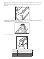
ASSEMBLY INSTRUCTIONS
1. Uncrate the stove and remove packing materials and protective poly bag. (save cardboard box for further
assembly.)
2. Remove parts from inside of stove. Parts include: one feed door, four legs, hardware pack, ue collar, hearth
plate, and bottom air channel.
3. Place attened carton on oor and carefully turn stove over onto carton.
4. Attach bottom air channel with four (4) 1/4-20 X 3/8" screw, and four (4) washers.
5. Attach hearth to bottom of stove with two (2) 1/4-20 x 1-3/16 screws, two (2) washers, and two (2) 1/4-20 jam
nuts.
REQUIRED TOOLS
• Safety Glasses
• Hearth Gloves
• Pencil
• 6' Folding Ruler or Tape Measure
• Tin Snips
• Drill
• 1/8" dia. Drill Bit
• Adjustable Wrench
• (Sheet Metal Screws)
• #2 philips screw driver
REQUIRED MATERIALS
• Note: the following items are not included with your
stove
• Flooring protector as specied
• Chimney Connector
• 1/2" Sheet Metal Screws
• Chimney
• Furnace Cement
CAUTION: Stove is heavy. Make sure you have adequate help and use proper lifting techniques whenever
moving stove.

-8-
6. Attach the front legs to hearth with two (2) 1/4-20 x 1-3/4 screws, two (2) at washers, and two (2) 1/4-20
jam nuts.
7. Attach the rear legs to base of stove with two (2) 1/4-20 x 1-3/4 screws, two (2) at washers, and two (2) 1/4-
20 jam nuts.
8. Carefully lift stove upright and place in desired location. Align the holes on the ue collar to the holes on the
stove and attach using (2) two 1/4-20 X 1-3/4 screws.
9. Lower feed door into position while aligning hinge pins.
KEY PART NO. DESCRIPTION QTY.
1 83658 1/4-20 X 1-3/16 Flathead Phillips Screw 4
2 83563 1/4-20 X 3/4 Flt Hd Ph Mach 4
3 83659 1/4-20 X 1-3/4 Flt Hd Ph Screw 4
4 83336 1/4-20 Jam Nut 10
5 83278 7/32 Id X 1/2 Od X 3/64 Fl W 10

-9-
Installation
MINIMUM CLEARANCE TO COMBUSTIBLE WALLS US, CANADA
HEATER/FLOOR PROTECTOR LOCATION (Dimensions are required for
non-protected surfaces. See chart for dimensions for protected surfaces.)
Place the heater on solid masonry or solid concrete. When the heater
is used on a combustible oor, use an Underwriters Listed oor protector.
The oor protector must comply with UL Standards (USA) and CAN/ULC
(Canada) and have an R-value of 2.06. The oor protector needs to
extend at least 16" beyond the door side of the heater and 8" to each side.
It should also extend 8" beyond the rear for Canada. The oor protector
needs to extend 2" beyond each side of the ue pipe if it is elbowed
towards a wall as well as 2" on each side of the ue for horizontal runs.
1. After consulting the installation instructions for minimum clearances
to combustibles, locate your oor protector accordingly and
carefully place the stove in your selected location. Install stove pipe,
elbows and thimble as necessary, utilizing either a recently cleaned
and inspected masonry chimney (properly lined) or a UL, ULC Listed
chimney. Insure that the xed ue bafe that is provided is installed
in the ue collar. This bafe is intended to be in a xed location for
optimal combustion. Do not remove or alter the location of this
bafe. It is against federal regulations and will void your warranty.
2. Again, check the following illustrations and be sure you have the
clearances shown from the heater and the connector pipe to
combustible surfaces. If you have a solid brick or stone wall behind
your heater, please consult your local building code for specic
regulations that may apply in your area. However, if the wall is only
faced with brick or stone, consider it a combustible wall. To reduce
ue clearances from combustible materials, contact your local
safety department.
3. If your chimney drafts excessively, purchase and use a Barometric
Draft Regulator (DR6 available from factory).
4. The chimney connection should be as short as possible, and the
heater must have its own ue. Do not connect this unit to a chimney
ue serving other appliances.
5. Use three sheet metal screws in each stove pipe and or elbow joint
to rmly hold the pipe together. Seal around the screws
6. Do not install this heater in a mobile home or trailer.
7. Check your local building and insurance codes. The installation must
comply with their rulings.
419mm
18”
419mm
18”
8”
203mm
CAUTION!
Keep furnishings and other combustible materials
away from the heater.
Non-Combustible Construction In Accordance With Nfpa 211
8”
203mm

-10-
Operation Of The Heater
1. Burn wood or wood products only. The wood should be well seasons prior to use for maximum efciency.
2. Provide air into the room for combustion.
3. Do Not touch the heater after ring until it has cooled.
4. Do Not use a grate or elevate re, build re directly on hearth. The fuel feed door must remain closed during
operation.
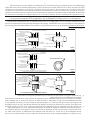
MASONRY CHIMNEY
The masonry chimney must comply with UL, ULC codes.
Before using an existing masonry chimney, clean the chimney
and inspect the ue liner to be sure it is safe to use. Make
repairs before attaching the heater. See Page 3, Item 5.
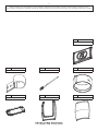
Look at Fig. 5. The connector pipe and ttings you will need
to connect directly to a masonry chimney are shown. If the
connector pipe must go through a combustible wall before
entering the masonry chimney, consult a qualied mason or
chimney dealer. The installation must conform to local re
codes, and NFPA 211(USA) or CAN/CSA-B365-M91(CANADA).
Do not connect this heater into the same chimney ue as the
replace or ue from another heater. The chimney used for a
heater must not be used to ventilate the cellar or basement. If
there is a cleanout opening at the base of the chimney, close
it tightly.
UL/ULC LISTED CHIMNEY
Carefully follow chimney manufacturer's instructions. Use only
listed type HT per UL, ULC 103, 6-in diameter black or blued
chimney connector, minimum 24 gauge steel. If your chimney
starts at the ceiling (Fig. 6), you will need enough 6" pipe to
reach the ceiling.
The top of the chimney must be at least 3 feet above the roof
and be at least 2 feet higher than any point of the roof within
10 feet. (Fig 6). Use double or triple wall pipe for the exterior
portion of the chimney.
RULES FOR CONNECTOR PIPE INSTALLATION
1. Crimped end of the pipe must be installed toward the
heater. The pipe should slide into the ue collar. The pipe
should be rmly attached to the ue collar with 3 screws
and sealed with furnace cement.
2. Slope any horizontal pipe upward toward the chimney
at least 1/4 inch for each foot of horizontal run. Horizontal
section must be a minimum of 24" from stove.
3. You must have at least 18" inches clearance between
any horizontal piping and the ceiling.
4. The pipe cannot extend into the chimney ue.(Fig. 7)
5. Seal each connector pipe joint with furnace cement.
Also, seal the pipe at the chimney. Seal the inside with
high temperature silicone and the outside with high
temperature tape.
6. Use 3 sheet metal screws at each joint to make the piping
rigid.
FIG. 5
ELBOW
COLLAR
THIMBLE
FLOOR PROTECTOR
FLUE CONNECTION-NON-COMBUSTIBLE WALL
PIPE
NONCOMBUSTIBLE WALL
PIPE
BAROMETRIC
DRAFT REGULATOR
WRONG
RIGHT
FIG. 6
FIG. 5
ELBOW
COLLAR
THIMBLE
PIPE REDUCER
FLOOR PROTECTOR
FLOOR PROTECTOR
3 FT. MIN.
2 FT. MIN
10 FT.
CHIMNEY CAP MANDATORY
11 FT. MINIMUM
FIG. 7
WRONG
FLUE CONNECTION-NON-COMBUSTIBLE WALL
PIPE
NONCOMBUSTIBLE WALL
PIPE
BAROMETRIC
DRAFT REGULATOR
BAROMETRIC
DRAFT REGULATOR
PIPE
NONCOMBUSTIBLE
CONSTRUCTION IN
ACCORDANCE WITH
NFPA 211
Chimney Connection

-11-
7. It is recommended that no more than two (2) 90 degree bends be used in the stove pipe installation as more
than two (2) may decrease the amount of draw and possibly cause smoke spillage.
NOTE: The chimney connector shall not pass through an attic, roof space, oor, ceiling, or similar concealed
space. Where passage through a wall or partition of combustible construction is desired, the installation must
conform with CAN/CSA - B365.
WRONG
RIGHT
FIG. 6
FIG. 5
ELBOW
COLLAR
THIMBLE
PIPE REDUCER
FLOOR PROTECTOR
FLOOR PROTECTOR
3 FT. MIN.
2 FT. MIN
10 FT.
CHIMNEY CAP MANDATORY
11 FT. MINIMUM
FIG. 7
WRONG
FLUE CONNECTION-NON-COMBUSTIBLE WALL
PIPE
NONCOMBUSTIBLE WALL
PIPE
BAROMETRIC
DRAFT REGULATOR
BAROMETRIC
DRAFT REGULATOR
PIPE
NONCOMBUSTIBLE
CONSTRUCTION IN
ACCORDANCE WITH
NFPA 211
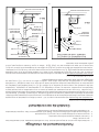
CONNECTION OF CHIMNEY CONNECTOR TO A MASONRY CHIMNEY THROUGH A COMBUSTIBLE WALL
Figure 8 shows how to connect the chimney connector of a heater to a masonry chimney through a combustible
wall. There are ve allowable ways that a chimney connector can be connected to a masonry chimney by
passing through a combustible wall. NFPA Standard 211 allows the following wall pass-through systems.
6
CONNECTION OF CHIMNEY CONNECTOR TO A MASONRY CHIMNEY THROUGH A COMBUSTIBLE WALL
Figure 8 shows how to connect the chimney connector of a heater to a masonry chimney through a combustible wall.
There are five allowable ways that a chimney connector can be connected to a masonry chimney by passing through
a combustible wall. NFPA Standard 211 allows the following wall pass-through systems.
MASONRY CHIMNEY
CONSTRUCTED TO
NFPA 211
AIRTIGHT
CLEANOUT
DOOR
FLOOR
PROTECTOR
COMBUSTIBLE WALL
TO
HEATER
CHIMNEY CONNECTOR
CEILING
SEE PARTS A, B,
C, D, AND E OF
THIS FIGURE FOR
OPTIONS.
CHIMNEY FLUE
FIGURE 8 -
CONNECTION OF CHIMNEY CONNECTOR TO A
MASONRY CHIMNEY THROUGH A COMBUSTIBLE
WALL
(FIGURE 8 CONTINUED ON NEXT PAGE)

-12-
7
MINIMUM 12 IN.
TO COMBUSTIBLES
PART A, FIGURE 8
(FIGURE 8 CONTINUED ON NEXT PAGE)
1. Use a minimum 3-1/2" thick brick masonry wall framed into the combustible wall. A fireclay liner (ASTM C315 or
equivalent) having a 5/8" minimum wall thickness must be used and it must be at least 12" away from any material
that could catch fire. The inside diameter of the fireclay liner shall be sized for the proper snug fit of a 6" diameter
chimney connector pipe. The fireclay liner shall run from the outer surface of the brick wall to, but not beyond, the
inner surface of the chimney flue and shall be firmly cemented in place. See Part A of Figure 8.
2. Use a solid insulated listed factory-built chimney length having an inside diameter of 6" and having 1" or more of
solid insulation. There must be at least a 9" air space between the outer wall of the chimney length and any
combustible materials. The inner end of the chimney length shall be flush with the inside of the masonry chimney , the
flue shall be sealed to the flue and to the brick masonry penetration with nonwater-soluble refractory cement. Sheet
steel supports which are at least 24 gauge(0.024") in thickness shall be securely fastened to wall
surfaces on all sides. Fasteners between supports and the chimney length shall not penetrate the chimney liner.
See Part B of Figure 8.
3. Use a 10" diameter ventilated thimble made of at least 24 gauge(0.024") steel having two 1" air channels. The venti-
lated thimble must be separated from combustible materials by a minimum of 6" glass fiber insulation. The opening
in the combustible wall shall be covered and the thimble supported with sheet steel supports which are at least 24
gauge (0.024") in thickness. The sheet steel supports shall be securely fastened to wall surfaces on all sides and
shall be sized to fit and hold the chimney section. Fasteners used to secure chimney sections shall not penetrate
chimney flue liner. See Part C of Figure 8.
4. Use an 8" inside diameter solid insulated listed factory-built chimney length which has 1" or more of solid insulation.
The minimum length of this chimney section shall be 12" and will serve as a pass-through for the 6" diameter
chimney connector. There must be at least a 12" air space between the outer wall of the chimney section and any
combustible materials. The chimney section shall be concentric with and spaced 1" away from the chimney connec
tor by means of sheet steel support plates on both ends of the chimney section. The opening in the combustible wall
shall be covered and the chimney section supported on both sides with sheet steel supports which are at least 24
gauge (0.024") in thickness. The sheet steel supports shall be securely fastened to wall surfaces on all sides and
shall be sized to fit and hold the chimney section. Fasteners used to secure chimney sections shall not penetrate
chimney flue liner. See Part C of Figure 8.
5. A listed factory-built wall pass-through system may be purchased and installed according to the instructions pack
aged with it to provide a safe method of passing the chimney connector through a combustible wall for connection
to a masonry chimney.
Additional requirements pertaining to Figure 8 and the above wall pass-through systems:
1. Insulation material used as part of wall pass-through system shall be of noncombustible material and shall have a
thermal conductivity of 1.0 Btu • in./ft.² • °F (4.88 kg • cal/hr • m² • °C) or less
2. All clearances and thicknesses are minimums: larger clearances and thickness are acceptable.
3. A chimney thimble, as shown for 3" and 4" above (Parts C and D respectively of Figure 8) shall be for types "3" and
4" connections to facilitate removal of the chimney connector for cleaning. The chimney thimble shall be of ASTM
C315 fireclay with 5/8" minimum wall thickness, or material of equivalent durability. The inside diameter of the
thimble shall be sized for the proper snug fit of a 6" diameter chimney connector pipe. The thimble shall be installed
without damage to the chimney flue. The thimble shall extend through the chimney wall to, but not beyond, the
inner surface of the chimney flue and shall be permanently cemented in place with high temperature cement.
4. A chimney connector to a masonry chimney, except for 2" above (Part B of Figure 8), shall extend through the wall
pass-through system to the inner face of the chimney flue, but not beyond. It does not have to be fastened in place
so long as it cannot accidently be pulled out of the chimney or shoved into the chimney flue. If fasteners are used
to secure the chimney connector to a masonry chimney, the fasteners shall not penetrate the chimney flue liner.
5. Any material used to close up any opening for the connector shall be noncombustible.
CHIMNEY FLUE
MINIMUM CHIMNEY CLEARANCE TO
BRICK AND COMBUSTIBLES IS 2 IN.
MINIMUM CLEARANCES 12 IN.
OF BRICK ALL AROUND
CHIMNEY CONNECTOR
TO HEATER
FIRE CLAY LINER
(5/8" MIN. WALL THICKNESS)
MIN. 3-1/2" THICK BRICK
MASONRY WALL
MASONRY CHIMNEY
CONSTRUCTED TO
NFPA 211
1. Use a minimum 3-1/2" thick brick masonry wall framed into the combustible wall. A reclay liner (ASTM C315
or equivalent) having a 5/8" minimum wall thickness must be used and it must be at least 12" away from any
material that could catch re. The inside diameter of the reclay liner shall be sized for the proper snug t of
a 6" diameter chimney connector pipe. The reclay liner shall run from the outer surface of the brick wall to,
but not beyond, the inner surface of the chimney ue and shall be rmly cemented in place. See Part A of
Figure 8.
2. Use a solid insulated listed factory-built chimney length having an inside diameter of 6" and having 1" or
more of solid insulation. There must be at least a 9" air space between the outer wall of the chimney length
and any combustible materials. The inner end of the chimney length shall be ush with the inside of the
masonry chimney , the ue shall be sealed to the ue and to the brick masonry penetration with nonwater-
soluble refractory cement. Sheet steel supports which are at least 24 gauge(0.024") in thickness shall be
securely fastened to wall surfaces on all sides. Fasteners between supports and the chimney length shall not
penetrate the chimney liner. See Part B of Figure 8.
3. Use a 10" diameter ventilated thimble made of at least 24 gauge(0.024") steel having two 1" air channels. The
ventilated thimble must be separated from combustible materials by a minimum of 6" glass ber insulation.
The opening in the combustible wall shall be covered and the thimble supported with sheet steel supports
which are at least 24 gauge (0.024") in thickness. The sheet steel supports shall be securely fastened to wall
surfaces on all sides and shall be sized to t and hold the chimney section. Fasteners used to secure chimney
sections shall not penetrate chimney ue liner. See Part C of Figure 8.
4. Use an 8" inside diameter solid insulated listed factory-built chimney length which has 1" or more of solid
insulation. The minimum length of this chimney section shall be 12" and will serve as a pass-through for the 6"
diameter chimney connector. There must be at least a 12" air space between the outer wall of the chimney
section and any combustible materials. The chimney section shall be concentric with and spaced 1" away
from the chimney connector by means of sheet steel support plates on both ends of the chimney section.
The opening in the combustible wall shall be covered and the chimney section supported on both sides
with sheet steel supports which are at least 24 gauge (0.024") in thickness. The sheet steel supports shall be
securely fastened to wall surfaces on all sides and shall be sized to t and hold the chimney section. Fasteners
used to secure chimney sections shall not penetrate chimney ue liner. See Part C of Figure 8.
5. A listed factory-built wall pass-through system may be purchased and installed according to the instructions
pack aged with it to provide a safe method of passing the chimney connector through a combustible wall
for connection to a masonry chimney.
ADDITIONAL REQUIREMENTS PERTAINING TO FIGURE 8 AND THE ABOVE WALL PASS-THROUGH SYSTEMS
1. Insulation material used as part of wall pass-through system shall be of noncombustible material and shall
have a thermal conductivity of 1.0 Btu • in./ft.² • °F (4.88 kg • cal/hr • m² • °C) or less
2. All clearances and thicknesses are minimums: larger clearances and thickness are acceptable.
3. A chimney thimble, as shown for 3" and 4" above (Parts C and D respectively of Figure 8) shall be for types "3"
and 4" connections to facilitate removal of the chimney connector for cleaning. The chimney thimble shall
be of ASTM C315 reclay with 5/8" minimum wall thickness, or material of equivalent durability. The inside
diameter of the thimble shall be sized for the proper snug t of a 6" diameter chimney connector pipe. The
thimble shall be installed without damage to the chimney ue. The thimble shall extend through the chimney
wall to, but not beyond, the inner surface of the chimney ue and shall be permanently cemented in place
with high temperature cement.

-13-
CONNECTION OF CHIMNEY CONNECTOR TO A MASONRY CHIMNEY WHEN CHIMNEY CONNECTOR
DOES NOT PASS THROUGH A COMBUSTIBLE WALL
PART E - (FIGURE 8)
In addition to the methods shown by A, B, C, and D of Figure 8, a listed factory-built wall pass-through system
may be purchased and installed according to the instructions packaged with it to provide a safe method of
passing chimney connector through a combustible wall for a connection to a masonry chimney.
If the chimney connector does not have to pass through a combustible wall to get to a masonry chimney, simply
connect the chimney connector directly to the masonry chimney's chimney thimble as described and shown
by parts C and D of Figure 8. Remember, the chimney connector should extend into the chimney thimble to
the inner face of the chimney ue but not beyond; if the chimney connector is extended through the chimney
thimble into the chimney ue, resistance to the ow of smoke and gases up the chimney will occur; that ow
resistance will have an adverse affect on the operation and performance of the heater and venting system.
8
CONNECTION OF CHIMNEY CONNECTOR TO A MASONRY CHIMNEY WHEN CHIMNEY CONNECTOR
DOES NOT PASS THROUGH A COMBUSTIBLE WALL
PART E - (Figure 8)
In addition to the methods shown by A, B, C, and D of Figure 8, a listed factory-built wall pass-through system
may be purchased and installed according to the instructions packaged with it to provide a safe method of
passing chimney connector through a combustible wall for a connection to a masonry chimney.
If the chimney connector does not have to pass through a combustible wall to get to a masonry chimney, simply connect
the chimney connector directly to the masonry chimney's chimney thimble as described and shown by parts C and D of
Figure 8. Remember, the chimney connector should extend into the chimney thimble to the innerface of the chimney flue
but not beyond; if the chimney connector is extended through the chimney thimble into the chimney flue, resistance to the
flow of smoke and gases up the chimney will occur; that flow resistance will have an adverse affect on the operation and
performance of the heater and venting system.
PART B
FIGURE 8 -
(FIGURE 8 CONTINUED)
AIR SPACE
9 IN. MINIMUM
FACTORY-BUILT
CHIMNEY LENGTH
SHEET STEEL SUPPORTS
CHIMNEY SECTION
CHIMNEY
CONNECTOR
AIR SPACE
2 IN.
TWO VENTILATED AIR
CHANNELS EACH 1 INCH.
CONSTRUCTED OF
SHEET STEEL.
PART C
FIGURE 8
PART D
FIGURE 8
MASONRY CHIMNEY CONSTRUCTED
TO NFPA 211
SHEET STEEL SUPPORTS
(24 GAUGE MIN. THICKNESS)
CHIMNEY CONNECTOR
TO HEATER
MINIMUM CHIMNEY CLEARANCES FROM MASONRY TO
SHEET STEEL SUPPORTS AND COMBUSTIBLES 2 IN.
MINIMUM 6 IN. GLASS
FIBER INSULATION ALL AROUND
24 GAUGE
VENTILATED THIMBLE WITH
TWO 1 INCH AIR CHANNELS
CHIMNEY THIMBLE
CHIMNEY FLUE
MINIMUM CHIMNEY CLEARANCES FROM MASONRY TO
SHEET STEEL SUPPORTS AND COMBUSTIBLES 2 IN.
CHIMNEY LENGTH
FLUSH WITH INSIDE
OF FLUE
NONSOLUBLE
REFACTORY
CEMENT
MASONRY CHIMNEY CONSTRUCTED
TO NFPA 211
CHIMNEY CONNECTOR
TO HEATER
MINIMUM CLEARANCE
9 IN. ALL AROUND
SHEET STEEL SUPPORTS
(24 GAUGE MIN. THICKNESS)
CHIMNEY FLUE
SOLID INSULATED, LISTED
FACTORY-BUILT CHIMNEY LENGTH
USE CHIMNEY MFRS. PARTS TO
ATTACH CONNECTOR SECURELY
AIR SPACE
CHIMNEY CONNECTOR
TO HEATER
SOLID INSULATED, LISTED
FACTORY-BUILT CHIMNEY
LENGTH (12 IN. LONG MIN.)
MINIMUM CLEARANCE
2 IN. ALL AROUND
CHIMNEY THIMBLE
1 IN. AIR SPACE TO
CHIMNEY LENGTH
MASONRY CHIMNEY CONSTRUCTED
TO NFPA 211
SHEET STEEL SUPPORTS
(24 GAUGE MIN. THICKNESS)
CHIMNEY FLUE
MINIMUM CHIMNEY CLEARANCES FROM MASONRY TO
SHEET STEEL SUPPORTS AND COMBUSTIBLES 2 IN.
8
4. A chimney connector to a masonry chimney, except for 2" above (Part B of Figure 8), shall extend through
the wall pass-through system to the inner face of the chimney ue, but not beyond. It does not have to be
fastened in place so long as it cannot accidently be pulled out of the chimney or shoved into the chimney
ue. If fasteners are used to secure the chimney connector to a masonry chimney, the fasteners shall not
penetrate the chimney ue liner.
5. Any material used to close up any opening for the connector shall be noncombustible.

-14-
CAUTION!
NEVER USE GASOLINE, GASOLINE-TYPE
LANTERN FUEL, KEROSENE, CHARCOAL
LIGHTER FLUID, OR SIMILAR
LIQUIDS TO START OR "FRESHEN UP" A
FIRE IN THE HEATER. KEEP ALL SUCH LIQUIDS WELL
AWAY FROM THE HEATER WHILE IT IS IN USE.
CAUTION: A chimney re may cause ignition of wall studs or rafters which you thought were a safe distance
from the chimney. If you have a chimney re, have your chimney inspected by a qualied person before
using again.
WARNING!
NEVER STORE FLAMMABLE LIQUIDS,
ESPECIALLY GASOLINE. IN THE
VICINITY OF THE HEATER.
CAUTION!
OVERFIRING THE APPLIANCE MAY
CAUSE A HOUSE FIRE. IF A UNIT OR
CHIMNEY CONNECTOR GLOWS, YOU
ARE OVERFIRING.
WARNING!
NEVER OPERATE THIS HEATER WITH THE FUEL
DOOR OPEN.
WARNING!
USE ONLY THE LEGS PROVIDED WITH THIS
HEATER. REFER TO STEP 5 IN THE "INSTALLATION"
SECTION OF THIS MANUAL.
CAUTION!
USE WOOD OR WOOD-LIKE MATERIALS
ONLY. DO NOT USE COAL OR
CHARCOAL. COAL OR CHARCOAL WILL
DESTROY THE FIREBOX. DO NOT USE
DRIED LUMBER OR TREATED WOOD.
NOTE:
DO NOT ELEVATE FIRE OR USE WITH A GRATE,
BUILD FIRE DIRECTLY ON THE HEARTH.
WARNING!
DO NOT OBSTRUCT THE SPACE BENEATH THE
HEATER
SERVICE HINTS
Do not expect a heater to draw. It is the chimney that creates the draft. Smoke spillage into the house or
excessive buildup of water or creosote in the chimney are warnings that the chimney is not functioning properly.
Correct problem before using heater. Possible causes are:
1. The connector pipe may push into the chimney too far, stopping the draft. (Fig. 7)
2. Do not connect two heaters into the same chimney ue.
3. The chimney used for a heater must not be used to ventilate the cellar or basement. If there is a cleanout
opening at the base of the chimney, it must be closed tightly.
4. If the chimney is operating too cool, water will condense in the chimney and run back into the stove.
Creosote formation will be rapid and may block the chimney. Operate the heater at a high enough re to
keep the chimney warm preventing this condensation.
5. If the re burns well but sometimes smokes or burns slowly, it may be caused by the chimney top being lower
than another part of the house or a nearby tree. The wind blowing over a house or tree, falls on top of the
chimney like water over a dam, beating down the smoke. The top of the chimney should be at least 3 feet
above the roof and be at least to 2 feet higher than any point of the roof within 10 feet.
Chimney Maintenance
CREOSOTE - FORMATION AND NEED FOR REMOVAL
When wood is burned slowly, it produces tar and other organic vapors, which combine with expelled moisture
to form creosote. The creosote vapors condense in the relatively cool chimney ue of a slow burning re. As a
result, creosote residue accumulates on the ue lining. When ignited, this creosote makes an extremely hot re.
The chimney connector and chimney should be inspected at least twice monthly during the heating season to
determine if a creosote buildup has occurred.
If creosote has accumulated, it should be removed. Failure to remove creosote may cause a house re. Creosote
may be removed by using a chimney brush or other commonly available materials.
Chimney res burn very hot. If the chimney connector should glow red, immediately call the re department,
then reduce the re by blocking/closing the inlet air. Since this is a single burnrate heater you should use a non-
combustible material to block inlet air openings. If the re is burning vigorously, spray a multipurpose dry chemical
extinguisher onto the re in the stove if it can be done safely. Avoid introducing water into the chimney if possible
as water could damage the heated ue liner.

-15-
Your heating unit was designed to burn wood only; no other materials should be burned. Waste and other
ammable materials should not be burned in your stove. Any type of wood may be used in your stove, but
specic varieties have better energy yields than others. Please consult the following table in order to make the
best possible choice.
WOODSTOVE UTILIZATION
It is EXTREMELY IMPORTANT that you use DRY WOOD only in your wood stove. The wood should have dried for 9
to 15 months, such that the humidity content (in weight) is reduced below 20% of the weight of the log. It is very
important to keep in mind that even if the wood has been cut for one, two or even more years, it is not necessarily
dry if it has been stored in poor conditions.
Under extreme conditions it may rot, instead of drying. This point cannot be over stressed; the vast majority of
the problems related to the operation of a wood stove is caused by the fact that the wood used was too damp
or has dried in poor conditions. These problems can be:
– ignition problems
– creosote build-up causing chimney res
– low energy yield
– blackened windows
– incomplete log combustion
Smaller pieces of wood will dry faster. All logs exceeding 6” in diameter should be split. The wood should not be
stored directly on the ground. Air should circulate through the cord. A 24” to 48” air space should be left between
each row of logs, which should be placed in the sunniest location possible. The upper layer of wood should be
protected from the elements but not the sides.
TESTING YOUR WOOD
When the stove is thoroughly warmed, place one piece of split wood (about ve inches in diameter) parallel to
the door on the bed of red embers.
Keep the air control full open by pulling on it and close the door. If ignition of the piece is accomplished within
90 seconds from the time it was placed in the stove, your wood is correctly dried. If ignition takes longer, your
wood is damp.
If your wood hisses and water or vapor escapes at the ends of the piece, your wood is soaked or freshly cut.
Do not use this wood in your stove. Large amounts of creosote could be deposited in your chimney, creating
potential conditions for a chimney re.
TYPE
WEIGHT
(LBS. CU. FT., DRY)
PER CORD
EFFICIENCY
RANKING
SPLITS
M I L L I O N S
BTU’s/CORD
Hickory 63 4500 1.0 Well 31.5
White Oak 48 4100 .9 Fair 28.6
Red Oak 46 3900 .8 Fair 27.4
Beech 45 3800 .7 Hard 26.8
Sugar Maple 44 3700 .6 Fair 26.2
Black Oak 43 3700 .6 Fair 25.6
Ash 42 3600 .5 Well 25.0
Yellow Birch 40 3400 .4 Hard 23.8
Red Maple 38 3200 .3 Fair 22.6
Paper Birch 37 3100 .3 Easy 22.1
Elm/Sycamore 34 2900 .2 Very Difcult 20.1
Red Spruce 29 1800 .1 Easy 16.1

-16-
THE FIRST FIRES
The fresh paint on your stove needs to be cured to preserve its quality. Once the fuel charge is properly ignited,
only burn small res in your stove for the rst four hours of operation.
Make sure that there’s enough air circulation while curing the stove. The odors could be smelled during the 3 or
4 rst res. Never start your stove outside. You will not be able to see if you are over heating.
RELOADING
Once you have obtained a good bed of embers, you should reload the unit. Open the door very slowly; open it
one or two inches for 5 to 10 seconds, before opening it completely to increase the draft and thus eliminate the
smoke which is stagnant in a state of slow combustion in the stove. Then bring the red embers to the front of the
stove and reload the unit.
It is important to note that wood combustion consumes ambient oxygen in the room. In the case of negative
pressure, it is a good idea to allow fresh air in the room, either by opening a window slightly or by installing a fresh
air intake system on an outside wall.
Creosote - Formation and Need for Removal - When wood is burned slowly, it produces tar and other organic
vapors, which combine with expelled moisture to form creosote. The creosote vapors condense in the relatively
cool chimney ue of a slow-burning re. As a result, creosote residue accumulates on the ue lining. When
ignited, this creosote makes an extremely hot re. The chimney connector and chimney should be inspected
at least once every two months during the heating season to determine if a creosote build-up has occurred. If
creosote has accumulated (3mm or more), it should be removed to reduce the risk of a chimney re.
We strongly recommend that you install a magnetic thermometer on your smoke exhaust pipe, approximately
18” above the stove. This thermometer will indicate the temperature of your gas exhaust fumes within the smoke
exhaust system. The ideal temperature for these gases is somewhere between 275°F and 500°F. Below these
temperatures, the build-up of creosote is promoted. Above 500 degrees, heat is wasted since a too large quantity
is lost into the atmosphere.
TO PREVENT CREOSOTE BUILD UP
• Always burn dry wood. This allows clean burns and higher chimney temperatures, therefore, less creosote
deposit.
• The secondary combustion can only take place if the rebox is hot enough.
• Always check for creosote deposit once every two months and have your chimney cleaned at least once a
year.
If a chimney or creosote re occurs, close all dampers (if applicable) immediately. Wait for the re to go out and
the heater to cool, then inspect the chimney for damage. If no damage results, perform a chimney cleaning to
ensure there is no more creosote deposits remaining in the chimney.
CAUTION:
Never alter the damper slide or the adjustment range to increase FIRING ring for any reason. Doing so could
result in heater damage and will void your warranty.
WARNINGS:
• NEVER OVERFIRE YOUR STOVE. IF ANY PART OF THE STOVE STARTS TO GLOW RED, OVER FIRING IS
HAPPENING.
• THE INSTALLATION OF A LOG CRADLE OR GRATES IS NOT RECOMMENDED IN YOUR WOOD STOVE BUILD FIRE
DIRECTLY ON HEARTH.

-17-
CAUTIONS:
ASHES COULD CONTAIN HOT EMBERS EVEN AFTER TWO DAYS WITHOUT OPERATING THE STOVE.
MAINTENANCE
Your wood stove is a high efciency stove and, therefore requires little maintenance. It is important to perform
a visual inspection of the stove every time it is emptied, in order to insure that no parts have been damaged,
in which case repairs must be performed immediately. Inspect and clean the chimney and connector pipe
periodically for creosote buildup or obstructions.
GASKETING
It is recommended that you change the door gasket (which makes your stove door air tight) once a year, in
order to insure good control over the combustion, maximum efciency, and security. To change the door gasket,
simply remove the damaged one. Carefully clean the available gasket groove, apply a high temperature silicone
sold for this purpose and install the new gasket. You may light up your stove again approximately 24 hours after
having completed this operation.
PAINT
Only clean your stove with a dry soft cloth that will not harm the paint nish. If the paint becomes scratched or
damaged, it is possible to give your wood stove a brand new look, by repainting it with a 1200° F heat resistant
paint. For this purpose, simply scrub the surface to be repainted with ne sand paper, clean it properly, and apply
thin coats (2) of paint successively.
SECONDARY AIR TUBES
The secondary air tubes must be cleaned with a wire brush. If debris remains in holes lightly tap with a wooden
stick to remove.
WARNING:
NEVER OPERATE THE STOVE WITHOUT A GASKET OR WITH A BROKEN ONE. DAMAGE TO THE STOVE OR EVEN
HOUSE FIRE MAY RESULT.

-18-
Parts List
In order to maintain warranty, components must be replaced using original manufacturers parts purchased through your
dealer or directly from the appliance manufacturer. Use of third party components will void the warranty.
KAO Wool
88228 1
Door Assembly
892515 1
Handle Assembly
892722 1
Bafe
892510 1
Bottom Channel
892508 1
Leg
40817 4
Hearth Extension
40771 1
6" Damper
40398 1
Rod
892533 4
3/8" Rope Joint Top
88033 8.75 ft
Tube Weldment
892516 1
Main Top
40774 1

-19-
Parts List
In order to maintain warranty, components must be replaced using original manufacturers parts purchased through your
dealer or directly from the appliance manufacturer. Use of third party components will void the warranty.
6" Damper Pivot Pin
892517 1
Handle Bracket
89975 1
Flue Collar
40784 1
Main Bottom
40772 1
Door Frame
40302 1
Main Back
40299 1
Main Side
40775 2

-20-
NOTES
La page est en cours de chargement...
La page est en cours de chargement...
La page est en cours de chargement...
La page est en cours de chargement...
La page est en cours de chargement...
La page est en cours de chargement...
La page est en cours de chargement...
La page est en cours de chargement...
La page est en cours de chargement...
La page est en cours de chargement...
La page est en cours de chargement...
La page est en cours de chargement...
La page est en cours de chargement...
La page est en cours de chargement...
La page est en cours de chargement...
La page est en cours de chargement...
La page est en cours de chargement...
La page est en cours de chargement...
La page est en cours de chargement...
La page est en cours de chargement...
La page est en cours de chargement...
La page est en cours de chargement...
La page est en cours de chargement...
La page est en cours de chargement...
-
 1
1
-
 2
2
-
 3
3
-
 4
4
-
 5
5
-
 6
6
-
 7
7
-
 8
8
-
 9
9
-
 10
10
-
 11
11
-
 12
12
-
 13
13
-
 14
14
-
 15
15
-
 16
16
-
 17
17
-
 18
18
-
 19
19
-
 20
20
-
 21
21
-
 22
22
-
 23
23
-
 24
24
-
 25
25
-
 26
26
-
 27
27
-
 28
28
-
 29
29
-
 30
30
-
 31
31
-
 32
32
-
 33
33
-
 34
34
-
 35
35
-
 36
36
-
 37
37
-
 38
38
-
 39
39
-
 40
40
-
 41
41
-
 42
42
-
 43
43
-
 44
44


United States Stove 1269E Le manuel du propriétaire
- Catégorie
- Poêle à bois
- Taper
- Le manuel du propriétaire
dans d''autres langues
Documents connexes
-
United States Stove 2469E Le manuel du propriétaire
-
-
-
-
-
 Hotblast 1500 Le manuel du propriétaire
-
US Stove Company TOOL14 Le manuel du propriétaire

Autres documents
-
US Stove US1269E Le manuel du propriétaire
-
Superior Fireplaces WXS2000 Mode d'emploi
-
 Regency Fireplace Products Pro-Series F3500 Le manuel du propriétaire
-
Ashley AWC31M Mode d'emploi
-
United States Stove Company VG2520 Series Wood Stove Le manuel du propriétaire
-
Classic Accessories 55-056-011501-00 Mode d'emploi
-
