red lion PGMMODC1 Communication Enabler Manuel utilisateur
- Taper
- Manuel utilisateur

Product Manual
PGMMODC1
Communication enabler
Model No. PGMMODC1
Drawing No. LP1097
Version No. 101
Revision Date 19/07


Communication enabler
PGMMODC1
Contents
Warning ................................................................................................ 4
Symbol identification .................................................................................... 4
Safety instructions ...................................................................................... 5
Applications ............................................................................................ 6
Technical characteristics ................................................................................. 6
Mounting / installation / programming .................................................................... 6
Mounting on a IAMS/AFCM device ........................................................................ 7
Electrical specifications.................................................................................. 8
PGMMODC1 installation examples ........................................................................ 9
Modbus basics .......................................................................................... 10
PGMMODC1 modbus parameter settings .................................................................. 11
PGMMODC1 Modbus settings - routing diagram ............................................................ 18
Ordering information .................................................................................... 20
LP1097 3

Warning
This device is designed for connection to hazardous electric voltages. Ignoring this warning can result in severe
personal injury or mechanical damage.
To avoid the risk of electric shock and fire, the safety instructions of this guide must be observed and the
guidelines followed. The specifications must not be exceeded, and the device must only be applied as described
in the following.
Prior to the commissioning of the device, this installation guide must be examined carefully.
Only qualified personnel (technicians) should install this device.
If the equipment is used in a manner not specified by the manufacturer, the protection provided by the
equipment may be impaired.
Warning
Until the device is fixed, do not connect hazardous voltages to the device. The following operations should only
be carried out on a disconnected device and under ESD safe conditions:
General mounting, connection and disconnection of Modbus cable.
Troubleshooting the device.
Warning
Repair of the device must be done by Red Lion Controls only.
Symbol identification
Triangle with an exclamation mark: Read the manual before installation and commissioning of the device in
order to avoid incidents that could lead to personal injury or mechanical damage.
The CE mark proves the compliance of the device with the essential requirements of the directives.
The double insulation symbol shows that the device is protected by double or reinforced insulation.
GENERAL
HAZARD-
OUS
VOLTAGE
CAUTION
4 LP1097

Safety instructions
Receipt and unpacking
Unpack the device without damaging it and check whether the device type corresponds to the one ordered. The packing should always
follow the device until this has been permanently mounted.
Environment
The device is manufactured for indoor use. Avoid direct sunlight, dust, high temperatures, mechanical vibrations and shock, as well as
rain and heavy moisture. If necessary, heating in excess of the stated limits for ambient temperatures should be avoided by way of
ventilation.
The device may be used in Overvoltage Category II, Pollution Degree 2 at an altitude up to 2000 m.
Mounting
Only qualified technicians who are familiar with the technical terms, warnings, and instructions in this installation guide and who are
able to follow these should connect the device. Only devices which are undamaged and free of moist and dust may be installed. The
device may be installed and supplied by Red Lion IAMS and AFCM series only.
Should there be any doubt as to the correct handling of the device, please contact your local distributor or, alternatively,
Red Lion Controls
www.redlion.net
Calibration and Adjustment
During calibration and adjustment, the measuring and connection of external voltages must be carried out according to the
specifications of this manual. The technician must use tools and instruments that are safe to use.
Cleaning
When disconnected, the device may be cleaned with a cloth moistened with distilled water.
Liability
To the extent the instructions in this manual are not strictly observed, the customer cannot advance a demand against Red Lion
Controls that would otherwise exist according to the concluded sales agreement.
Special Condition of Use:
1) In Class I, Division 2 installations, the subject equipment shall be mounted within a tool-secured enclosure which is capable of
accepting one or more of the Class I, Division 2 wiring methods specified in the National Electrical Code (ANSI/NFPA 70) or Canadian
Electrical Code (C22.1)
2) In Class I, Zone 2 installations, the subject equipment shall be mounted within a tool-secured enclosure which is capable of
accepting one or more of the Class I, Zone 2 wiring methods specified in the National Electrical Code (ANSI/NFPA 70) or Canadian
Electrical Code (C22.1).
The equipment shall be installed in an enclosure with a minimum ingress protection rating of IP54 unless the apparatus is intended to
be afforded an equivalent degree of protection by location.
Conditions particulières d’utilisation :
1) Dans les installations de classe I, division 2, l’équipement visé doit être installé dans un boîtier protégé par un outil pouvant
accepter une ou plusieurs des méthodes de câblage de classe I, division 2 spécifiées dans le Code national de l’électricité (ANSI/
NFPA 70) ou le Code électrique canadien (C22.1).
2) Dans les installations de classe I, zone 2, l’équipement visé doit être monté à l’intérieur d’un boîtier protégé par un outil
pouvant accepter une ou plusieurs des méthodes de câblage de classe I, zone 2 spécifiées dans le Code national de l’électricité
(ANSI/NFPA 70) ou le Code électrique canadien (C22.1).
L’équipement doit être installé dans un boîtier dont l’indice de protection est d’au moins IP54, à moins que l’appareil ne soit
destiné à recevoir un degré de protection équivalent selon l’emplacement.
LP1097 5

Communication enabler
PGMMODC1
• Programming display for IAMS and AFCM devices
• Modbus RTU protocol interface over RS-485
• Monitor process value from the built-in display
• High 2.5 kV isolation to host unit
• Shielded RJ45 Modbus connector on top
Applications
• The PGMMODC1 detachable display adds Modbus RTU RS-485 serial communications to all current and future IAMS/AFCM units.
• The unit converts a wide array of sensors and analog device signals measured by the device, like uni- and bipolar mA and voltage
signals, potentiometer, Lin. R, RTD and TC, to a Modbus communication line signal.
• When mounted on an IAMS/AFCM device any signal coming from or going to I.S. classified area, like AI, AO, DI and DO signals, can be
converted to a Modbus network.
• All individual unit operating parameters can easily and quickly be configured by using the Modbus communication or by using the
front display menu.
• The easily readable PGMMODC1 display can be used to read the process signal, simulate the output signal, indicate sensor errors
and internal module errors.
Technical characteristics
• PGMMODC1 has full PGM functionality for unit programming, process signal monitoring and diagnostics handling.
• Modbus RTU protocol is supported using a serial RS-485 communication wiring.
• Multidrop half-duplex connection via shielded RJ45 connector.
• High safe galvanic isolation of 2.5 kVAC between the serial wiring and the connected system IAMS/AFCM units.
• Modbus parameters such as address, baud rate, stop bit(s), and parity bit are configured from the PGMMODC1 display, which also
stores parameters.
Mounting / installation / programming
• Mounting in Zone 2 / Div 2.
• The PGMMODC1 can be moved from one device to another. The individual system IAMS/AFCM unit configuration of the first
transmitter can be saved and downloaded to subsequent transmitters.
• Programmed parameters can be protected by a user-defined password.
• When mounted on devices that are installed upside down, a menu item allows the display on the PGMMODC1 to be rotated 180
and the up/down buttons to switch function.
6 LP1097

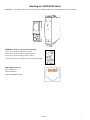
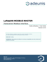
Mounting on a IAMS/AFCM device
PGMMODC1 is a detachable display that can be mounted on all IAMS/AFCM fronts for programming and signal monitoring.
PGMMODC1 contains a four line LCD dot display
Line 1 can e.g. show the scaled process value.
Line 2 can e.g. show the selected engineering unit.
Line 3 can e.g. show the analog output or TAG no.
Line 4 shows status for communication and e.g. signal trending.
RJ45 Modbus Connector
Pin 5: RS485 A line
Pin 4: RS485 B line
Pin 8: RS485 GND and shield
LP1097 7

Electrical specifications
Environmental conditions:
Specifications range . . . . . . . . . . . . . . . . . . . . . . . . . . . . . . . . . . -20°C to +60°C
Storage temperature . . . . . . . . . . . . . . . . . . . . . . . . . . . . . . . . . -20°C to +85°C
Humidity. . . . . . . . . . . . . . . . . . . . . . . . . . . . . . . . . . . . . . . . . < 95% RH (non-cond.)
Protection degree . . . . . . . . . . . . . . . . . . . . . . . . . . . . . . . . . . . IP20
Installation in pollution degree 2 / overvoltage category II.
Mechanical specifications:
Dimensions (HxWxD) . . . . . . . . . . . . . . . . . . . . . . . . . . . . . . . . . 73.2 x 23.3 x 26.5 mm
Dimensions (HxWxD) w/ IAMS/AFCM unit . . . . . . . . . . . . . . . . . . . . . 109 x 23.5 x 131 mm
Weight approx. . . . . . . . . . . . . . . . . . . . . . . . . . . . . . . . . . . . . . 100 g
Connection . . . . . . . . . . . . . . . . . . . . . . . . . . . . . . . . . . . . . . . RJ45 - shielded
Common specifications:
Power consumption . . . . . . . . . . . . . . . . . . . . . . . . . . . . . . . . . . ≤ 0.15 W
Isolation voltage - test / working . . . . . . . . . . . . . . . . . . . . . . . . . . 2.5 kVAC / 250 VAC
reinforced isolation
Signal / noise ratio . . . . . . . . . . . . . . . . . . . . . . . . . . . . . . . . . . . > 60 dB
Update rate / response time . . . . . . . . . . . . . . . . . . . . . . . . . . . . . > 50 Hz / < 20 ms
Signal type . . . . . . . . . . . . . . . . . . . . . . . . . . . . . . . . . . . . . . . RS-485 half duplex
Serial protocol . . . . . . . . . . . . . . . . . . . . . . . . . . . . . . . . . . . . . Modbus RTU
Modbus mode. . . . . . . . . . . . . . . . . . . . . . . . . . . . . . . . . . . . . . RTU - slave
Devices on an RS485 line . . . . . . . . . . . . . . . . . . . . . . . . . . . . . . Up to 32 (without a repeater)
Data rates, baud . . . . . . . . . . . . . . . . . . . . . . . . . . . . . . . . . . . . 2400, 4800, 9600, 19200,
38400, 57600, 115200
Automatic baudrate detection . . . . . . . . . . . . . . . . . . . . . . . . . . . . Yes - can be configured ON or OFF
Parity. . . . . . . . . . . . . . . . . . . . . . . . . . . . . . . . . . . . . . . . . . . Even, Odd, None
Stop bit(s) . . . . . . . . . . . . . . . . . . . . . . . . . . . . . . . . . . . . . . . . 1 or 2
Digital adressing . . . . . . . . . . . . . . . . . . . . . . . . . . . . . . . . . . . . 1...247
Response delay. . . . . . . . . . . . . . . . . . . . . . . . . . . . . . . . . . . . . 0...1000 ms
Approvals:
EMC 2004/108/EC . . . . . . . . . . . . . . . . . . . . . . . . . . . . . . . . . . . EN 61326-1
LVD 2006/95/EC . . . . . . . . . . . . . . . . . . . . . . . . . . . . . . . . . . . . EN 61010-1
UL, Standard for Safety . . . . . . . . . . . . . . . . . . . . . . . . . . . . . . . . UL 61010-1
UL Listed . . . . . . . . . . . . . . . . . . . . . . . . . . . . . . . . . . . . . . . . E179259
Ex:
FM . . . . . . . . . . . . . . . . . . . . . . . . . . . . . . . . . . . . . . . . . . . . FM19US0016X
CL I DIV2 GP A- D T5
CL I Zn2 Groups IIC T5
CL I Zn2 AEx nA IIC T5
8 LP1097

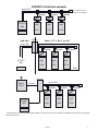
PGMMODC1 installation examples
*
Termination Resistors are not required when talking to other Red Lion devices. However, a 120 Ohm resistor may be required with
other master devices.
IAMS
/
AFCM
IAMS
/
AFCM
IAMS
/
AFCM
PGMMOD
IAMS
/
AFCM
IAMS
/
AFCM
IAMS
/
AFCM
PGMMODPGMMOD
IP54
IAMS
/
AFCM
IAMS
/
AFCM
IAMS
/
AFCM
PGMMOD PGMMODPGMMOD
PGMMOD PGMMODPGMMOD
T
*
T
*
T
*
Modbus RTU
Zone 2 / Cl. 1, Div. 2, gr. A-DSafe Area
Modbus RTU
Gateway
Gateway
Modbus RTU
Ethernet
Modbus TCP/IP
PLC/DCS
HMI
PLC/DCS
HMI
Modbus RTU
PLC/DCS
HMI
Access
Point
(see addition at the
bottom of this page)
LP1097 9

Modbus basics
Modbus is a “master-slave” system..., where the “master” communicates with one or multiple “slaves”.
The master typically is a PLC (Programmable Logic Controller), DCS (Distributed Control System), HMI (Human Machine Interface), or
RTU (Remote Terminal Unit).
The three most common Modbus versions used are: MODBUS ASCII, MODBUS RTU and MODBUS/TCP.
In Modbus RTU, data is coded in binary, and requires only one communication byte per data byte. This is ideal for use over multi-drop
RS485 networks, at speeds up to 115,200 bps.
The most common speeds are 9,600 bps and 19,200 bps.
Modbus RTU is the most widely used industrial protocol and is supported by the PGMMODC1.
Modbus RTU:
To communicate with a slave device, the master sends a message containing:
Device Address - Function Code - Data - Error Check
The Device Address is a number from 0 to 247.
Messages sent to address 0 (broadcast messages) will be accepted by all slaves, but numbers 1-247 are addresses of specific devices.
With the exception of broadcast messages, a slave device always responds to a Modbus message so the master knows the message
was received.
PGMMODC1 Supported Modbus Function Codes:
Command
Function code
Read Holding Registers 03
Read Input Registers 04
Write Single Register 06
Diagnostics 08
Write Multiple Registers 16
The Function Code defines the command that the slave device is to execute, such as read data, accept data, report status. Some
function codes have subfunction codes.
The Data defines addresses in the device’s memory map for read functions, contains data values to be written into the device’s
memory, or contains other information needed to carry out the function requested.
The Error Check is a 16-bit numeric value representing the Cyclic Redundancy Check (CRC).
Maximum number of registers which can be read or written at once:
For a read command, the limit is 8 registers at a baud rate up to 38,400 bps, 16 registers @ 57,800 bps and 32 registers @ 115,200
bps.
For a write command, the limit is 123 registers at baud rates up to 115,200 bps.
10 LP1097

PGMMODC1 modbus parameter settings
Automatic Baudrate Detection:
Can be configured YES or NO
Supported baudrates:
2400, 4800, 9600, 19.2k, 38.4k, 57.6k, 115.2k bps
Parity Mode:
Even, Odd or None parity
Stop Bits:
1 or 2 stop bits
Response delay:
0...1000 ms (0 ms = default)
Modbus slave addressing range:
1 - 247 (247 = default address)
Modbus Parameter Storage:
Saved in non-volatile memory in the PGMMODC1 device
(Factory Default Values are marked in bold)
LP1097 11

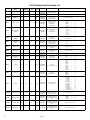
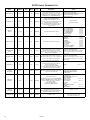
AFCM Configuration Parameter List
Category
Parameter
Name
No.
Register
Address
Register
Size
Read/
Write
Type Description Values
GENERAL DEVICE NUMBER 0 0 1 RO
UNSIGNED
INTEGER
Defines the
actual device type
AFCM = 16930 (0xAFCM)
GENERAL DEVICE VERSION 1 1 1 RO
UNSIGNED
INTEGER
Product version 0
GENERAL PASSWORD 2 2 1 R/W
UNSIGNED
INTEGER
Password
for entering
configuration menu
Range: 0...9999
INPUT INPUT TYPE 3 3 1 R/W
UNSIGNED
INTEGER
Selected input type
(Voltage, Current,
Resistance,
Potentiometer,
Temperature)
TEMP = 0
POTM = 1
LINR = 2
CURR = 3
VOLT = 4
INPUT
INPUT VOLTAGE
RANGE
4 4 1 R/W
UNSIGNED
INTEGER
Fixed input range for
voltage
measurements
0...1 V = 0
0.2...1 V = 1
0...2.5 V = 2
0.5...2.5 V = 3
0...5 V = 4
1...5 V = 5
0...10 V = 6
2...10 V = 7
INPUT
INPUT CURRENT
RANGE
5 5 1 R/W
UNSIGNED
INTEGER
Fixed input range for
current
measurements
0...20 mA = 0
4...20 mA = 1
INPUT
CONNECTION
TYPE
6 6 1 R/W
UNSIGNED
INTEGER
Sensor
connection type
for RTD / resistance
measurements
2-wire = 0
3-wire = 1
4-wire = 2
INPUT LIN RES LOW 7 7 1 R/W
UNSIGNED
INTEGER
Input range low for
Linear resistance meas-
urements
Range: 0...9998
INPUT LIN RES HIGH 8 8 1 R/W
UNSIGNED
INTEGER
Input range high for
Linear resistance meas-
urements.
Range: 1...9999
INPUT TEMP UNIT 9 9 1 R/W
UNSIGNED
INTEGER
Temperature units
°C = 0
°F = 1
INPUT
TEMP SENSOR
TYPE
10 10 1 R/W
UNSIGNED
INTEGER
Temperature
sensor type
TC = 0
Ni = 1
Pt = 2
INPUT PT TYPE 11 11 1 R/W
UNSIGNED
INTEGER
Pt value
(Pt10, Pt20, Pt50...)
Pt10 = 0
Pt20 = 1
Pt50 = 2
Pt100 = 3
Pt200 = 4
Pt250 = 5
Pt300 = 6
Pt400 = 7
Pt500 = 8
Pt1000 = 9
INPUT NI TYPE 12 12 1 R/W
UNSIGNED
INTEGER
Ni value
(Ni50, Ni100...)
Ni50 = 0
Ni100 = 1
Ni120 = 2
Ni1000 = 3
INPUT TC TYPE 13 13 1 R/W
UNSIGNED
INTEGER
Thermocouple type
(TCB, TCK...)
TC type B = 0
TC type E = 1
TC type J = 2
TC type K = 3
TC type L = 4
TC type N = 5
TC type R = 6
TC type S = 7
TC type T = 8
TC type U = 9
TC type W3 = 10
TC type W5 = 11
TC type Lr = 12
DISPLAY DISPLAY UNIT 14 14 1 R/W
UNSIGNED
INTEGER
Units shown as display
units for non-tempera-
ture input types
acc. to table 1
DISPLAY DECIMAL POINT 15 15 1 R/W
UNSIGNED
INTEGER
Decimal point place
for display reading of
non-temperature input
types
XXXX = 0
X.XXX = 1
XX.XX = 2
XXX.X = 3
DISPLAY DISPLAY LOW 16 16 1 R/W INTEGER
Low display range
for display reading of
non-temperature input
types.
Range: -1999...9999
DISPLAY DISPLAY HIGH 17 17 1 R/W INTEGER
High display range
for display reading of
non-temperature input
types
Range: -1999...9999
12 LP1097

OUTPUT OUTPUT TYPE 18 18 1 R/W
UNSIGNED
INTEGER
Output type:
Programmable pulse is
available for:
Frequency < 500 Hz
Pulses < 30,000 p/m
< 1,800,000 p/hour
< 43,200,000 p/day
DC 50% = 0
Prog Pulse = 1
OUTPUT OUTPUT UNIT 19 19 1 R/W
UNSIGNED
INTEGER
Output unit
Hz = 0
p/min = 1
p/hour = 2
p/day = 3
OUTPUT
FREQUENCY LOW
/ PULSE LOW
20 20 2 R/W
UNSIGNED
INTEGER
Frequency output
low value in mHz or
1/1000nds of pulses
per min./hour/day
Range with frequency selected: 0...25000000
Range with p/min. selected: 60...30000000
Range with p/hour selected: 3600...30000000
Range with p/day selected: 86400...30000000
OUTPUT
FREQUENCY HIGH
/ PULSE HIGH
21 22 2 R/W
UNSIGNED
INTEGER
Frequency output
high value in mHz or
1/1000nds of pulses
per min./hour/day
Range with frequency selected: 0...25000000
Range with p/min. selected: 60...30000000
Range with p/hour selected: 3600...30000000
Range with p/day selected: 86400...30000000
OUTPUT
CUTOFF
FREQUENCY /
PULSE
22 24 2 R/W
UNSIGNED
INTEGER
Cutoff frequency in mHz
or 1/1000nds of pulses
per min./hour/day
Range with frequency selected: 0...25000000
Range with p/min. selected: 60...30000000
Range with p/hour selected: 3600...30000000
Range with p/day selected: 86400...30000000
OUTPUT PULSE TIME 23 26 1 R/W
UNSIGNED
INTEGER
Pulse length in ms,
must be set less than 0.9
x (1 / Fmax)
Range: 1...1000
OUTPUT INDICATE ERROR 24 27 1 R/W
UNSIGNED
INTEGER
Use a specific
frequency to
indicate errors
NO = 0
YES = 1
OUTPUT
ERROR
FREQUENCY
25 28 2 R/W
UNSIGNED
INTEGER
Frequency to
indicate an error in mHz
or 1/1000nds of pulses
per min./hour/day
Range with frequency selected: 0...26250000
Range with pulse selected: 0...31500000
OUTPUT RESPONE TIME 26 30 1 R/W
UNSIGNED
INTEGER
Response time in 1/10 s
Range for non-temperature inputs: 4...600 (0.4...60 s)
Range for temperature inputs: 10...600 (1...60 s)
OUTPUT OUTPUT LOW 27 31 2 R/W INTEGER
Specific output
value low. Dependant of
selected input.
For temperature types
value is 1/10°.
Range equals the measurement range for the selected
sensor type and must be lower than OUTPUT HIGH
OUTPUT OUTPUT HIGH 28 33 2 R/W INTEGER
Specific output
value high. Dependant
of selected input.
For temperature types
value is 1/10°.
Range equals the measurement range for the selected
sensor type and must be higher than OUTPUT LOW
DISPLAY
DISPLAY
CONTRAST
29 35 1 R/W
UNSIGNED
INTEGER
Contrast in the LCD
display
Range: 0...9
DISPLAY
DISPLAY
BACKLIGHT
30 36 1 R/W
UNSIGNED
INTEGER
Backlight intensity in
LCD
Range: 0...9
DISPLAY TAG TEXT 31 37 3 R/W ASCII CHAR
Tag of the device
(6 characters)
Range: ASCII values from 32 to 90 (‘ ‘ to ‘Z’).
DISPLAY LINE 3 FUNCTION 32 40 1 R/W
UNSIGNED
INTEGER
Information shown
in line 3 of display in
monitor mode (normal
mode). Choose between
the output
frequency value or the
configured tag.
Output value = 0
TAG = 1
INPUT USE CALIB 33 41 1 R/W
UNSIGNED
INTEGER
Use the applied calibra-
tion values
NO = 0
YES = 1
GENERAL
ENABLE
PASSWORD
34 42 1 R/W
UNSIGNED
INTEGER
Password
protect entry to
configuration menu
NO = 0
YES = 1
INPUT
CALIB RANGE
LOW
35 43 2 R/W FLOAT
Actual process value for
low calibration point in
either display values or
1/10 °C
For non-temperature input types range is DISPLAY
LOW...DISPLAY HIGH
For temperature input types the range equals the
measurement range for the selected sensor type
INPUT
CALIB RANGE
HIGH
36 45 2 R/W FLOAT
Actual process value for
high calibration point in
either display values or
1/10 °C
As CALIB RANGE LOW
INPUT CALIB POINT LOW 37 47 2 R/W FLOAT
Measured process value
for low calibration point
in either display values
or 1/10 °C. (Must be cop-
ied from PROCESS DATA)
As CALIB RANGE LOW
INPUT
CALIB POINT
HIGH
38 49 2 R/W FLOAT
Measured process value
for high calibration point
in either display values
or 1/10 °C
(Must be copied from
PROCESS DATA)
As CALIB RANGE LOW
LP1097 13

GENERAL
HELP TEXT
LANGUAGE
39 53 1 R/W
UNSIGNED
INTEGER
Language for the help
texts shown in display
UK = 0
DK = 1
DE = 2
FR = 3
SE = 4
IT = 5
ES = 6
GENERAL CHECKSUM 100 100 1 RO
UNSIGNED
INTEGER
CRC16 checksum of the
configuration
Range 0...65536
GENERAL
Configuration
counter
101 101 1 R0
UNSIGNED
INTEGER
This counter will count
the number of times the
configuration has been
changed. The counter is
reset on power-up
Range 0...65536
14 LP1097

Table 1: Display units
0 °C 10 mils 20 in/s 30 kHz 40 MPa 50 GW 60 mV 70 gal/h
1 °F 11 yd 21 ips 31 Hz 41 kPa 51 MW 61
W
71 t/h
2 K 12 m
3
22 ft/s 32 p/min 42 hPa 52 kW 62 S 72 mol
3 % 13 L 23 in/min 33 p/h 43 bar 53 hp 63 µS 73 pH
4 m 14 s 24 ft/min 34 p/day 44 mbar 54 A 64 m
3
/min 74 [blank]
5 cm 15 min 25 in/h 35 t 45 kJ 55 kA 65 m
3
/h
6 mm 16 m/s 26 ft/h 36 kg 46 Wh 56 mA 66 l/s
7 µm 17 mm/s 27 m/s
2
37 g 47 MWh 57 µA 67 l/min
8 Ft 18 m/min 28 mm/s
2
38 N 48 kWh 58 V 68 l/h
9 in 19 m/h 29 rpm 39 Pa 49 W 59 kV 69 gal/min
AFCM Input Types and Ranges
Input type Min. value Max. value Standard
mA
V
Pt10...Pt1000
Ni50...Ni1000
Lin. R
Potentiometer
TC B
TC E
TC J
TC K
TC L
TC N
TC R
TC S
TC T
TC U
TC W3
TC W5
TC LR
0 mA
0 V
-200°C
-200°C
0 W
10 W
0°C
-100°C
-100°C
-180°C
-200°C
-180°C
-50°C
-50°C
-200°C
-200°C
0°C
0°C
-200°C
20 mA
10 V
+850°C
+250°C
10000 W
100 kW
+1820°C
+1000°C
+1200°C
+1372°C
+900°C
+1300°C
+1760°C
+1760°C
+400°C
+600°C
+2300°C
+2300°C
+800°C
-
-
IEC 60751
DIN 43760
-
-
IEC 60584-1
IEC 60584-1
IEC 60584-1
IEC 60584-1
DIN 43710
IEC 60584-1
IEC 60584-1
IEC 60584-1
IEC 60584-1
DIN 43710
ASTM E988-90
ASTM E988-90
GOST 3044-84
LP1097 15

AFCM Process Parameter List
Parameter
Name
No.
Register
Address
Register
Size
Read/
Write
Type Description Values
DISPLAY VALUE 0 1000 2 RO INTEGER
The measured value in 1/10 of °C/°F for
temperature Input types, or the scaled
display value for non-temperature input types
(INTEGER version of PRIMARY VALUE)
Range for non-temperature input types:
DISPLAY LOW...DISPLAY HIGH
Range for temperature input types: equals
the measurement range for the
selected sensor type
PERCENT PV 1 1002 1 RO INTEGER
The relative input value as 1/100 of %
calculated from PRIMARY VALUE.
For temperature input types 0...100%
corresponds the selected temperature range
(OUTPUT LOW...OUTPUT HIGH)
For non-temperature input types 0...100%
corresponds the selected fixed range
(e.g. 4...20 mA)
Range: 0...9999
(e.g. 7898 = 78.98%)
MEASURE
STATUS
2 1003 1 RO INTEGER The actual measurement status
OUTPUT UNDERRANGE: bit 0=1
OUTPUT OVERRANGE: bit 1= 1
OUTPUT LOW LINITED: bit 2= 1
OUTPUT HIGH LIMITED: bit 3= 1
INPUT UNDERRANGE: bit 4= 1
INPUT OVERRANGE: bit 5= 1
SENSOR SHORTED: bit 6= 1
SENSOR BROKEN: bit 7= 1
ERROR STATUS 3 1004 1 RO INTEGER The actual error status (Device errors)
AD COMM. ERROR bit 0= 1
CJC ERROR bit 1= 1
RAM ERROR bit 2= 1
EEP ERROR bit 3= 1
FLASH ERROR bit 4= 1
NOT CALIBRATED bit 5= 1
BAD OUTPUT bit 6= 1
NO OUTPUT bit 7= 1
OUTPUT SUPPLY ERROR bit 8= 1
INPUT SUPPLY ERROR bit 9= 1
PRIMARY RAW
VALUE
5 1005 2 RO FLOAT
The measured value in 1/10 of °C/°F for
temperature Input types, or the scaled
display value for non-temperature input types,
NOT PROCESS CALIBRATED.
Range for non-temperature input types:
DISPLAY LOW...DISPLAY HIGH
Range for temperature input types equals
the measurement range for the selected
sensor type
PRIMARY VALUE 6 1007 2 R/W F LOAT
The measured value in 1/10 of °C/°F for
temperature Input types, or the scaled display
value for non-temperature input types
Range for non-temperature input types:
DISPLAY LOW...DISPLAY HIGH
Range for temperature input types equals
the measurement range for the selected
sensor type
RELATIVE PV 7 1009 2 RO FLOAT
The relative input value calculated
from PRIMARY VALUE.
For temperature input types relative to
selected temperature range
(OUTPUT LOW...OUTPUT HIGH)
For non-temperarure input types relative to
selected fixed range (e.g. 4...20 mA)
Range: 0.0...1.0
OUTPUT
FREQUENCY
8 1011 2 R/W F LOAT
Calculated output value in mHz or 1/1000nds
of pulses per min./hour/day
Range with frequency selected:
0...25000000 (0...25000 Hz)
Range with pulse selected:
0...30000000
MEASURE
CONTROL
9 1013 1 R/W INTEGER
Measurement control.
By disabling update of certain READ/WRITE
parameters PRIMARY VALUE, OUTPUT VALUE or
RELAY STATUS, these can be simulated
by writing values.
All bits are cleared when
TIMEOUT COUNTER reaches 0
RESTART SCAN bit 0 = 1
RESTART WITH
NEW CONFIGURATION bit 1 = 1
DISABLE PRIMARY
VALUE UPDATE bit 2 = 1
DISABLE OUTPUT
VALUE UPDATE bit 3 = 1
NOT USED bit 4 = 1
DISABLE
CONFIGURATION CHECK bit 5 = 1
GET NEW
CONFIGURATION bit 6 = 1
TIMEOUT
COUNTER
10 1014 1 R/W INTEGER
Time out counter,
decrements every 0.075 second.
When reaching 0 (if not refreshed) all bits in
MEASURE CONTROL will be cleared.
Range: 0...255
INTERNAL
TEMPERATURE
11 1015 1 RO INTEGER
Internal measured or connector temperature
in 1/10 of °C/°F
Range:
-200...800 (-20.0...80.0 °C) or
-40...1760 (-4.0...176.0 °F)
16 LP1097

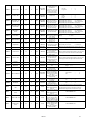
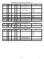
PGMMODC1 modbus Configuration Parameter List
Parameter
Name
No.
Register
Address
Register
Size
Read/
Write
Type Description Values
ENABLE MODBUS 1 3000 1 R/W INTEGER
Enable Modbus communication.
If disabled, PGMMODC1 ignores all frames sent
from the Modbus master and the only way to
re-enable Modbus communication is by using the
PGMMODC1 menu.
NO = 0
YES = 1
BAUDRATE 2 3001 1 R/W INTEGER
The baud value used for
Modbus communication
2400 BAUD = 0
4800 BAUD = 1
9600 BAUD = 2
19200 BAUD = 3
38400 BAUD = 4
57600 BAUD = 5
115200 BAUD = 6
ENABLE
AUTOBAUD
3 3002 1 R/W INTEGER
Enable automatic baudrate detection.
If enabled, PGMMODC1 determines the baudrate
automatically by listening to frames sent
on the Modbus line.
NO = 0
YES = 1
PARITY 4 3003 1 R/W INTEGER Configures parity check on Modbus frames
NONE = 0
EVEN PARITY = 1
ODD PARITY = 2
STOPBITS 5 3004 1 R/W INTEGER
Configures the number of stopbits in Modbus
frames
ONE STOPBIT = 1
TWO STOPBITS = 2
ADDRESS 6 3005 1 R/W INTEGER
Configures the Modbus address of the PGMMODC1
(Address 0 is broadcast address)
Range: 1...247
RESPONSE
DELAY
7 3006 1 R/W INTEGER
Configures minimum delay for Modbus
response in ms
Range: 0...1000
PGMMODC1 Additional Parameter List
Parameter
Name:
Nr.
Register
Address:
Register
Size:
Read/
Write:
Type: Description: Values
ROTATE DEVICE 1 3100 1 R/W INTEGER
Enables the display and key buttons to be used
normally when the host device is mounted
upside down
NO = 0
YES = 1
PGMMODC1 Modbus Status Parameter List
Parameter
Name
No.
Register
Address
Register
Size
Read/
Write
Type Description Values
AUTOBAUD
STATUS
1 4000 1 RO INTEGER Actual state of automatic baudrate detection
2400 BAUD = 0
4800 BAUD = 1
9600 BAUD = 2
19200 BAUD = 3
38400 BAUD = 4
57600 BAUD = 5
115200 BAUD = 6
SEARCHING = 7
ERROR = 8
IDENTIFY DEVICE 2 4001 1 R/W INTEGER
Enables the device to flash the LCD
background with appr. 4 Hz.
Value will automatically return to NO if
not written within 10 seconds!
NO = 0
YES = 1
MAXIMUM READ
REGISTERS
3 4002 1 RO INTEGER
Maximum allowed number of registers
that can be read in one command, with
the given/detected baudrate
Range: 8...32
LP1097 17

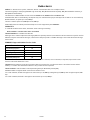
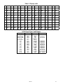
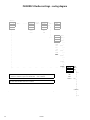
PGMMODC1 Modbus settings - routing diagram
"Monitor"
40.0
0000
(correct)
No
(No)
xxxx
%
---OK-->
--------->
PASSW.
---OK-->
ADV.SET
---OK-->
XXXX
10.4mA
[1]
[2]
(Yes)
[x]
^ o
V
v ^
v ^
|
v ^
|
9999
YES
|
|
0000
NO
|
|
|
|
|
MEM
(MEM)
|
|---->
SETUP
-OK-|-->
|
[3]
|
|
(DISP)
|
v ^
|-->
|
MEM
|
|
DISP
(CAL)
|
CAL
|-->
|
SIM
|
|
PASS
(SIM)
|
LANG
|-->
|
MODB
|
|
(PASS)
|
|-->
|
|
|
(LANG)
| |-->
|
|
| (MODB) YES (OFF)
|--> ------- ------- ------- ------- ------- - ------ ------- |--> MOD.EN ---OK-->
[4]
(ON) |
|
! ! ! Returns to "Monitor" from any menu, after 1 min with no keypress.
ON
|
! ! ! Returns to "Monitor" upon successful Modbus write command.
OFF
|
STATUS
|
|
|
|
|
|
(STATUS)
|
|
*1)
Only if automatic baudrate detection is enabled
|---->
|---->
*1) |
18 LP1097

SCROLLING HELP TEXTS:
[1]
Set correct password
[2]
Enter advanced setup menu?
[3]
Enter Language setup
Enter Password setup
Enter Simulation mode
Perform Process calibration
Enter Display setup
Perform Memory operations
Enter Modbus setup
Enter Rotation setup
[4]
Enable modbus communication
Disable Modbus communication
See automatic baudrate detection status
[5]
Reset Modbus to default?
[6]
Select Modbus slave address
[7]
Select parity for Modbus
[8]
Select number of stop bits
[9]
Select response delay in ms
[10]
Enable automatic baudrate detection
[11]
Modbus baudrate not detected
Searching for Modbus baudrate
Modbus baudrate detected
[12]
Select baudrate in bps
(OFF)
----- ------- ------- ------- ------- ------- ----- -- ---------> "Monitor"
(ON)
^
^
NO
(Yes)
|
|
MOD.RST ---OK--> ----| |
[5]
(No) |
|
|
247
EVEN
1
20
NO
(Yes)
|
v ^ |----> ADR AUTO.B ---OK--> ------- -------> ----|
YES ^| )oN(]01[]9[]8[]7[]6[
NO
|
|
|^ v^ v^ v^ v^ v 19.2k |
247 EVEN 1 1000 YES
|---->
BAUD OK -|
| ODD 2 | NO [12]
1
NONE
0
v ^
*1)
2400
SEAR 4800
------- ------- ------- ---------> STATUS ---OK--> "Monitor" 9600
[11]
19.2k
38.4k
ERR 57.6k
SEAR 115.2k
2400
4800
9600
19.2k
38.4k
57.6k
115.2k
"Monitor"
RSP.DLYSTP.BITPARITY
------- ------- --
*1)
Only if automatic baudrate detection is enabled
STATUS
Default settings:
Baud rate: 19.2 kbps
Parity mode: Even
Stop bit: 1
Address: 247
Reponse delay: 0 ms
LP1097 19

Ordering information
DESCRIPTION PART NUMBER
Communication/Programming Module Interface PGMMODC1
20 LP1097
-
 1
1
-
 2
2
-
 3
3
-
 4
4
-
 5
5
-
 6
6
-
 7
7
-
 8
8
-
 9
9
-
 10
10
-
 11
11
-
 12
12
-
 13
13
-
 14
14
-
 15
15
-
 16
16
-
 17
17
-
 18
18
-
 19
19
-
 20
20


red lion PGMMODC1 Communication Enabler Manuel utilisateur
- Taper
- Manuel utilisateur
dans d''autres langues
Documents connexes
Autres documents
-
AEG X66453MV1 Guide d'installation
-
AEG X66453BV10 Guide d'installation
-
Hager HTG411H Mode d'emploi
-
 Sollae Systems SMG-5620 Manuel utilisateur
-
Anybus AB7316 Guide d'installation
-
Eaton DG1-357D6FB-C21C Communications Manual
-
 ADEUNIS Modbus Mode d'emploi
-
 Adeunis RF LoRaWAN MODBUS MASTER 868 Manuel utilisateur
-
 ADEUNIS MODBUS V1.0.1 Mode d'emploi
-
 ADEUNIS MODBUS V1.0.1 Mode d'emploi


