Sony Camera Flash HVL-F32X Manuel utilisateur
- Catégorie
- La caméra clignote
- Taper
- Manuel utilisateur
Ce manuel convient également à

3-083-085-14 (1)
Flash
Sony Corporation 2003 Printed in Japan
HVL-F32X
Operating Instructions
Mode d’emploi
Manual de instrucciones
GB
FR
ES

2-GB
English
WARNING
To prevent fire or shock hazard, do not expose the unit to rain or moisture.
To avoid electrical shock, do not open the cabinet. Refer servicing to
qualified personnel only.
IMPORTANT SAFETY
INSTRUCTION
When using your electronic flash, basic safety
precautions should always be followed,
including the following:
1 Read and understand all instructions before
using.
2 Care must be taken as burns can occur from
touching hot parts.
3 Do not operate appliance if it has been
dropped or damaged, until it has been
examined by a qualified serviceman.
4 To reduce the risk of electric shock, do not
immerse this appliance in water or other
liquids.
5 To reduce the risk of electric shock, do not
disassemble this appliance, but take it to a
qualified serviceman when service or repair
work is required. Incorrect reassembly can
cause electric shock when the appliance is
used subsequently.

3-GB
6 The use of an accessory attachment not
recommended by the manufacturer may
cause a risk of fire, electric shock, or injury
to persons.
SAVE THESE
INSTRUCTIONS
Note:
This equipment has been tested and found to comply with the limits for a
Class B digital device, pursuant to Part 15 of the FCC Rules. These limits
are designed to provide reasonable protection against harmful interference
in a residential installation. This equipment generates, uses, and can
radiate radio frequency energy and, if not installed and used in accordance
with the instructions, may cause harmful interference to radio
communications. However, these is no guarantee that interference will not
occur in a particular installation. If this equipment does cause harmful
interference to radio or television reception, which can be determined by
turning the equipment off and on, the user is encouraged to try to correct
the interference by one or more of the following measures:
— Reorient or relocate the receiving antenna.
— Increase the separation between the equipment and receiver.
— Connect the equipment into an outlet on a circuit different from that to
which the receiver is connected.
— Consult the dealer or an experienced radio/TV technician for help.
You are cautioned that any changes or modifications not expressly
approved in this manual could void your authority to operate this
equipment.
For the customers in Germany
Directive: EMC directive 89/336/EEC, 92/31/EEC
This equipment complies with EMC regulations when used under the
following circumstances:
•Residential area
•Business district
•Light-industry district

4-GB
Table of contents
Features .................................................................................................................. 5
Caution ................................................................................................................... 6
Cleaning ................................................................................................................. 6
Parts identification ............................................................................................... 7
Names and functions of the parts ...................................................................... 8
Display panel ........................................................................................................ 9
Installing the batteries........................................................................................ 10
Closing the battery cover................................................................................... 11
Mounting the flash ............................................................................................. 12
Using the flash .................................................................................................... 15
Meaning of READY lamp states....................................................................... 20
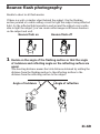
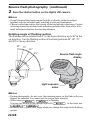
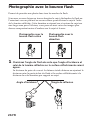
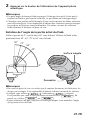
Bounce flash photography ................................................................................ 21
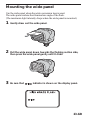
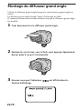
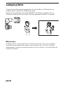
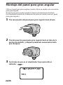
Mounting the wide panel .................................................................................. 23
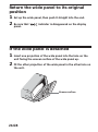
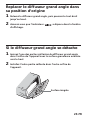
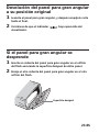
Return the wide panel to its original position................................................ 24
If the wide panel is detached ............................................................................ 24
Power save mode................................................................................................ 25
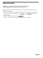
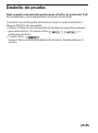
Test flash .............................................................................................................. 26
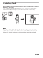
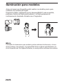
Modeling flash .................................................................................................... 27
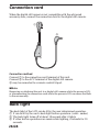
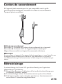
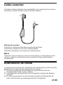
Connection cord.................................................................................................. 28
Back light ............................................................................................................. 28
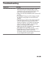
Troubleshooting.................................................................................................. 29
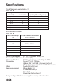
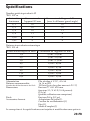
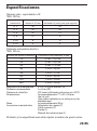
Specifications....................................................................................................... 30

5-GB
Features
•This unit is exclusively for use with digital still cameras with an
advanced accessory shoe or ACC terminal made by SONY.
•Using its pre-flash function flash photographs with the correct exposure
can be taken.*
•With it’s AF illuminator function the auto focus works even in dark
locations.*
* There are some types of digital still cameras with which this flash cannot
be used.

6-GB
Caution
•The flash cannot be used on camcorders.
•Removing or attaching this unit to a digital still camera while the power
is ON, or disconnecting the connection cord while the power is ON can
cause the flash to fire erroneously.
•When the flash is used in low-temperature conditions, battery
performance is reduced. For example, the number of flashes becomes
lower than that in room temperature (about 20°C), and the charging time
becomes longer. We recommend preparing new batteries. Note,
however, that even batteries whose performance has dropped due to low
temperatures are restored by returning them to room temperature.
•Do not leave or store the flash in temperatures that exceed 40°C. Doing
so might adversely affect the internal structure of video flash.
(In particular, take care not to leave the flash in automobiles during
summer.)
•The nameplate is located on the bottom exterior.
Cleaning
Remove this unit from the digital still camera. Clean the flash with a dry
soft cloth. In case of stubborn stains, use a cloth lightly dampened with a
mild detergent solution, then wipe the unit clean with a dry soft cloth.
Never use strong solvents, such as thinner or benzine, as these damage the
surface finish.

7-GB
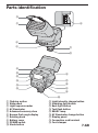
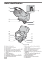
1 Flashing section
2 Wide panel
3 Light exposure meter
4 AF illuminator
5 Advanced accessory shoe
6 Bounce flash angle display
7 Rotating knob
8 Battery cover
9 POWER switch
q; Mode button
Parts identification
qa Light intensity change button
qs Modeling light button
qd Back light button
qf Test flash button
qg READY lamp
qh AF illuminator change button
qj Display panel
qk Connection cord terminal
ql Cord clamper
2
1
4
3
6
8
qh
qg
qf
qd
qs
9
qj
q;
qa
qk
ql
5
7

8-GB
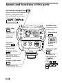
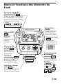
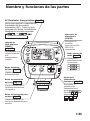
Names and functions of the parts
AF illuminator change button p. 18
Button to set the AF illuminator
quantity, each press of the
button changes the indication
in the following order.
t
t No display
READY lamp
p. 20
This lights up
when battery
charging is
completed.
Test flash
button p. 26
The flash fires
when pressed.
Setting the light
intensity
p. 17
For setting the
light intensity in
mode.
Press + or – to
select 1/32 , 1/16 ,
1/8 , 1/4 , 1/2 , or
1/1 .
POWER switch
The power (ON/
OFF) switch
Mode button
p. 16
The 3 modes
may be
selected.
Back light button
p. 28
The display panel
lights up for about 10
seconds.
Modeling light button
p. 27
When pressed the
modeling light comes on.

9-GB
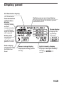
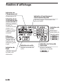
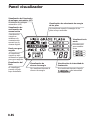
Display panel
Battery power warning display
Displayed when the battery power
has become low.
AF illuminator display
AF illuminator
Communication
confirmation
display
Display when
normal
communication
is established
with the digital
still camera.
Wide panel
Displayed
when the wide
panel is in use.
Flash display
Displayed when
the flash has
fired.
Power saving display
Displayed during power
saving.
Light intensity display
Displays the light intensity
during
mode.
Mode display
Display for
switching
between

10-GB
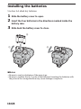
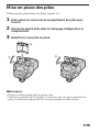
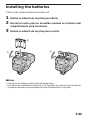
Installing the batteries
Use four AA alkali dry batteries.
1 Slide the battery cover to open.
2 Insert the four batteries in the directions marked inside the
battery case.
3 Slide back the battery cover to close.
PNotes
• Be sure to use four batteries of the same type.
• Be sure to confirm the 3 # poles of the batteries. Inserting the batteries with
the poles in the wrong direction may cause leakage or ruptures.
1
2
3

11-GB
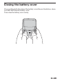
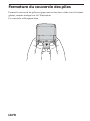
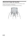
Closing the battery cover
Close pushing both the sides of the battery cover like an illustration, when
you slide and close the battery cover.
It can close the battery cover surely.

12-GB
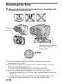
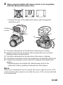
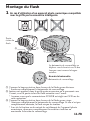
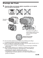
Mounting the flash
1 When using the digital still camera which is compatible with
the advanced accessory shoe
1 Turn the rotating knob in the direction of the arrow to loosen.
* Raise the lock pin fully.
2 Insert this unit into the accessory shoe towards the front, with the
flashing section facing forward.
* Be sure that the POWER switch is OFF when inserting.
3 Turn the rotating knob in the direction of the arrow to tighten.
* Lower the lock pin fully. If it is not fully lowered then this unit may
fall down.
* When attaching or removing this unit from the digital still camera,
loosen the rotating knob fully, and raise the lock pin fully.
The lock pin moves up and
down by turning the
rotating knob.
Pin Name
Lock pin
1
2
Flashing
section
3

13-GB
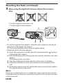
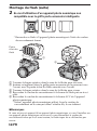
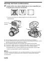
2 When using the digital still camera which is not compatible
with the advanced accessory shoe
* Connect this unit to the digital still camera with the supplied
connection cord.
1 Turn the rotating knob in the direction of the arrow to loosen.
2 Insert this unit into the accessory shoe towards the front, with the
flashing section facing forward.
3 Turn the rotating knob in the direction of the arrow to tighten.
4 Attach the connection cord to the connection cord terminal of this unit.
5 Connect the connection cord to the ACC terminal of the digital still
camera.
*Depending upon the digital still camera being used, fix the
connection cord by pressing it between the cord clamper.
PNote
Removing or attaching this unit to a digital still camera while the power is ON,
or disconnecting the connection cord while the power is ON can cause the flash
to fire erroneously.
1
2
3
4
5
Flashing
section

14-GB
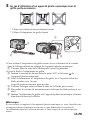
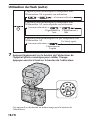
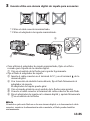
Mounting the flash (continued)
3 When using the digital still camera without the accessory
shoe
* Use the supplied connection cord.
* Use the supplied shoe adaptor.
•To use the supplied shoe adaptor, attach the shoe adaptor to the tripod
screw hole of the digital still camera.
1 Turn in the direction of the arrow to tighten lightly.
•Attach this unit to the shoe adaptor.
2 Insert the connection cord into the ACC terminal and the terminal
of the digital still camera.
3 With the flashing section facing forward, securely attach it to the shoe
adaptor.
The accessory shoe can rotate.
4 Turn the rotating knob in the direction of the arrow to tighten.
5 Attach the connection cord to the connection cord terminal of this
unit.
6 Fit the shoe adaptor onto the digital still camera and securely tighten
1 in the direction of the arrow.
PNote
Removing or attaching this unit to a digital still camera while the power is ON,
or disconnecting the connection cord while the power is ON can cause the flash
to fire erroneously.
1
3
2
4
5
6

15-GB
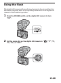
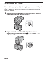
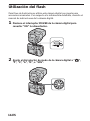
Using the flash
This digital still camera with an advanced accessory shoe is used here for
illustration purposes. Refer to the operating instructions of the digital still
camera for each detailed operation.
1 Press the POWER switch on the digital still camera to turn
“ON”.
2 Set the mode dial on the digital still camera to “ ”, “P”, “S”,
“A”, “M”, or “SCN”.

16-GB
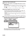
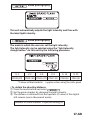
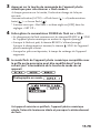
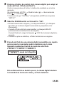
Using the flash (continued)
3 Press the control button on the digital still camera to choose
“Flash mode”.
Each press of the button changes the indication in the following order.
No display (AUTO) t Forced flash ( ) t Slow synchro ( ) t No
flash ( )
* Be sure that “Hot Shoe” is set to [OFF] in the “SET UP” settings.
4 Slide the POWER switch on this unit to “ON”.
•The flash starts to be charged, and the READY lamp and /CHG
lamp on the digital still camera start to flash (orange).
•When the flash is ready to fire, the READY lamp on this unit lights
(orange).
When the charging is finished, the /CHG lamp on the digital still
camera goes out.
•When the batteries are run down, it takes longer to charge this unit.
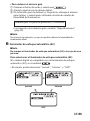
5 The flash mode of the digital still camera compatible with the
advanced accessory shoe can be changed in the following
order by the mode button on this unit.
/ /
mode photography
This unit performs a pre-flash, the disital still camera calculates
the ideal light intensity, and make this unit flash.

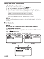
17-GB
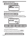
mode photography
This unit automatically adjusts the light intensity and fires with
the ideal light intensity.
mode photography
The mode in which the user can set the light intensity.
The light intensity can be selected using the “light intensity
change button” on this unit by the following procedure.
1/1 1/2 1/4 1/8 1/16 1/32
GN32 (22) GN22 (16) GN16 (11) GN11 (8) GN8 (6) GN6 (4)
* Values within brackets ( ) applies when using the wide panel
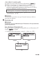
• To obtain the shooting distance
1 Press the mode button and select .
2 Set the guide number by changing the light intensity.
3 The distance is obtained from the aperture (F-value) of the digital
still camera (use in the manual mode).
Distance = Guide Number ÷ Aperture setting (F)

18-GB
Using the flash (continued)
• To obtain the guide number
1 Press the mode button and select .
2 Set the aperture on the digital still camera.
3 From the formula for distance and aperture obtain the optimum
guide number, and select it using the light intensity change button.
Guide Number = Aperture setting (F) × Distance
For Guide Numbers, refer to “Specifications”. (p. 30)
PNote
Do not close the light exposure meter or the ideal light intensity will not be
obtained.
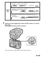
6 AF illuminator
PNote
Do not bring the AF illuminator close to person’s eyes, and flash.
To select the AF illuminator
If the digital still camera is compatible with an external AF illuminator
then is displayed.
•The user can select “normal,” “strong” and “OFF”
normal strong
OFF

19-GB
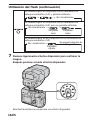
7 Lightly press the digital still camera shutter button to confirm
the image.
Then press the shutter button further.
This unit fires in conjunction with the shutter button.
The disital still camera is compatible with the AF
illuminator, and allow of using it.
t t No display
The disital still camera is compatible with the AF
illuminator, but prohibit using it.
No displayt t
Slow flashing Slow flashing
The digital still camera is not compatible with the AF
illuminator.
No displayt
Fast flashing
It turns off after about
2 seconds.

20-GB
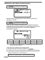
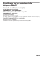
Meaning of READY lamp states
When it light (orange)
Flash is ready for firing.
When it flashes (orange)
Flash is charging. Firing is not possible.
When it flashes (red)
The batteries are run down.
Replace with new batteries.
(Charging takes longer if the flash has not been used for a long time.)
When the READY does not light
The flashing is prohibited.
(When the digital still camera excepts the shooting mode.)
La page est en cours de chargement...
La page est en cours de chargement...
La page est en cours de chargement...
La page est en cours de chargement...
La page est en cours de chargement...
La page est en cours de chargement...
La page est en cours de chargement...
La page est en cours de chargement...
La page est en cours de chargement...
La page est en cours de chargement...
La page est en cours de chargement...
La page est en cours de chargement...
La page est en cours de chargement...
La page est en cours de chargement...
La page est en cours de chargement...
La page est en cours de chargement...
La page est en cours de chargement...
La page est en cours de chargement...
La page est en cours de chargement...
La page est en cours de chargement...
La page est en cours de chargement...
La page est en cours de chargement...
La page est en cours de chargement...
La page est en cours de chargement...
La page est en cours de chargement...
La page est en cours de chargement...
La page est en cours de chargement...
La page est en cours de chargement...
La page est en cours de chargement...
La page est en cours de chargement...
La page est en cours de chargement...
La page est en cours de chargement...
La page est en cours de chargement...
La page est en cours de chargement...
La page est en cours de chargement...
La page est en cours de chargement...
La page est en cours de chargement...
La page est en cours de chargement...
La page est en cours de chargement...
La page est en cours de chargement...
La page est en cours de chargement...
La page est en cours de chargement...
La page est en cours de chargement...
La page est en cours de chargement...
La page est en cours de chargement...
La page est en cours de chargement...
La page est en cours de chargement...
La page est en cours de chargement...
La page est en cours de chargement...
La page est en cours de chargement...
La page est en cours de chargement...
La page est en cours de chargement...
La page est en cours de chargement...
La page est en cours de chargement...
La page est en cours de chargement...
La page est en cours de chargement...
La page est en cours de chargement...
La page est en cours de chargement...
La page est en cours de chargement...
La page est en cours de chargement...
La page est en cours de chargement...
La page est en cours de chargement...
La page est en cours de chargement...
La page est en cours de chargement...
La page est en cours de chargement...
La page est en cours de chargement...
La page est en cours de chargement...
La page est en cours de chargement...
-
 1
1
-
 2
2
-
 3
3
-
 4
4
-
 5
5
-
 6
6
-
 7
7
-
 8
8
-
 9
9
-
 10
10
-
 11
11
-
 12
12
-
 13
13
-
 14
14
-
 15
15
-
 16
16
-
 17
17
-
 18
18
-
 19
19
-
 20
20
-
 21
21
-
 22
22
-
 23
23
-
 24
24
-
 25
25
-
 26
26
-
 27
27
-
 28
28
-
 29
29
-
 30
30
-
 31
31
-
 32
32
-
 33
33
-
 34
34
-
 35
35
-
 36
36
-
 37
37
-
 38
38
-
 39
39
-
 40
40
-
 41
41
-
 42
42
-
 43
43
-
 44
44
-
 45
45
-
 46
46
-
 47
47
-
 48
48
-
 49
49
-
 50
50
-
 51
51
-
 52
52
-
 53
53
-
 54
54
-
 55
55
-
 56
56
-
 57
57
-
 58
58
-
 59
59
-
 60
60
-
 61
61
-
 62
62
-
 63
63
-
 64
64
-
 65
65
-
 66
66
-
 67
67
-
 68
68
-
 69
69
-
 70
70
-
 71
71
-
 72
72
-
 73
73
-
 74
74
-
 75
75
-
 76
76
-
 77
77
-
 78
78
-
 79
79
-
 80
80
-
 81
81
-
 82
82
-
 83
83
-
 84
84
-
 85
85
-
 86
86
-
 87
87
-
 88
88


Sony Camera Flash HVL-F32X Manuel utilisateur
- Catégorie
- La caméra clignote
- Taper
- Manuel utilisateur
- Ce manuel convient également à
dans d''autres langues
Documents connexes
-
Sony HVL-FH1100 Manuel utilisateur
-
Sony HVL-F43M Manuel utilisateur
-
Sony HVL-F60M Manuel utilisateur
-
Sony HVL-F45RM Manuel utilisateur
-
Sony HVL-F60RM Manuel utilisateur
-
Sony HVL-F56AM Manuel utilisateur
-
Sony HVL-F32M Manuel utilisateur
-
-