Tripp Lite SUT40KMBP & SUT60KMBP Mode d'emploi
- Taper
- Mode d'emploi

1
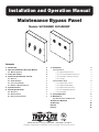
Maintenance Bypass Panel
Models: SUT40KMBP, SUT60KMBP
Installation and Operation Manual
1111 W. 35th Street, Chicago, IL 60609 USA • www.tripplite.com/support
Copyright © 2018 Tripp Lite. All trademarks are the sole property of their respective owners.
Contents
1. Introduction 2
2. Important Information About this Manual 2
2.1 Manual Symbols 2
3. Safety Precautions 2
4. Inspection Upon Receipt of Goods 3
4.1 General 3
4.2 Visible Damage 3
4.3 Concealed Damage 3
4.4 Return of Damaged Goods 3
5. System Overview 3
6. System Specifications 3
6.1 Electrical 3
6.2 Environmental 3
6.3 General Specifications 3
7. Installation 4
7.1 Preparation 4
7.1.1 Equipment Inspection 4
7.1.2 Necessary Equipment and Tools 4
7.1.3 Installation Safety Precautions 4
7.1.4 Storage 4
7.2 Installation Steps 4
7.2.1 Equipment Location 4
7.2.2 Equipment Mounting 4
7.2.3 Equipment Connections 4
7.2.4 Pre-Energizing Inspection 5
7.2.5 Energizing 5
8. System Operation 6
9. Maintenance 7
9.1 Short Circuits and Overloads 7
10. Reference Materials 8
11. Warranty 10
Español 11
Français 21

2
SAVE THESE INSTRUCTIONS!
This manual contains important information that is needed during the installation and maintenance of the system.
3. Safety Precautions
1. Introduction
2. Important Information About this Manual
2.1 Manual Symbols
Warning:
Indicates information provided to protect the user against personal injury, safety hazards and/or possible equipment damage.
Electrical Hazard:
Indicates that an electrical hazard exists that will result in personal injury or death if instructions are not followed.
Important:
Indicates information provided as an installation or operating instruction or tip, as well as general important installation and system
information.
Tripp Lite would like to thank you for choosing our product for your equipment needs. We know there are a lot of choices and we appreciate
the opportunity to supply each of our customers with the highest-quality power products manufactured in the United States today. All of our
solutions are factory-tested to the highest standards.
Sales support for future equipment needs or upgrades is provided by our regional sales staff and qualified representatives. All technical
questions and service issues should be directed to our main office by visiting www.tripplite.com/support.
Tripp Lite
www.tripplite.com
Technical Support
www.tripplite.com/support
Before installing or maintaining this equipment, it is extremely important to read this manual and be sure that all equipment drawings
and schematics are reviewed and clearly understood. If there are any questions concerning this manual or any of the installation or
maintenance procedures and/or requirements, please contact a Tripp Lite representative before proceeding.
Information in this manual is not intended for use as a training manual for nonqualified personnel.
When installing this equipment, always follow all applicable federal, state and local regulations to ensure safe and proper equipment
installation.
Only qualified persons should attempt to install or service this equipment. A qualified person is one who has skills and knowledge
related to the construction and operation of electrical equipment and installations and has received safety training on the hazards
involved.
Equipment installation and maintenance should always be performed with heavily insulated tools. It is also recommended to wear
rubber gloves and boots and to use insulating mats to stand on when working on this equipment.
Always wear eye protection when installing or maintaining power equipment.
To avoid personal injury, including electrical shock, severe burns and possible death, all jewelry, including bracelets, rings and
watches, must be removed prior to installing or servicing this equipment.
For the safety of others, never leave an open cabinet or panel unattended.
Any modifications to the equipment without authorization by Tripp Lite could result in equipment damage, personal injury or death.
Never work on power equipment while it is energized. De-energize equipment and lock off all power to the equipment before working
inside.
Inspection and maintenance should only be performed on equipment that has been de-energized and electrically isolated so that no
accidental contact can be made with energized parts.

3
4. Inspection Upon Receipt of Goods
5. System Overview
4.1 General
Special precautions and care have been taken to ensure the system arrives safe and undamaged. However, upon receipt, you should inspect
the entire shipment, including the crate and any boxes, for evidence of damage that may have occurred during transit.
4.2 Visible Damage
It is the responsibility of the person receiving the shipment to inventory and fully inspect all materials against the bill of lading or waybill
IMMEDIATELY while the carrier representative is still present. Ensure that all items are accounted for, including number of skids and quantity
of boxes. Also note any visible external damage that may have occurred during transit. Make all applicable notations on the delivery receipt
before signing and file a damage report with the carrier.
4.3 Concealed Damage
Within 3 to 30 days of receipt (depending on courier), unpack the system and check for any concealed damage. Check the materials
received against the detailed packing list to verify the quantity and the condition as complete and satisfactory.
Note any damage to the internal packaging. Then request an inspection by the carrier and file a concealed damage claim. If there is a
material shortage, visit www.tripplite.com/support to file a claim.
Please contact your shipping company for all shipping damage. Tripp Lite is not responsible for any shipping damage.
4.4 Return of Damaged Goods
Should equipment be damaged and require return to Tripp Lite for repair, a representative will provide instructions along with an RMA number
to expedite the return.
An RMA number must be obtained before returning equipment to Tripp Lite.
The Tripp Lite SUT40KMBP and SUT60KMBP Maintenance Bypass Panel (MBP) is used in conjunction with an Uninterruptable Power Supply
(UPS) to maintain total continuity of power to connected load circuits when bypass of the UPS equipment is required for performance of
regular service and maintenance.
The SUT40KMBP and SUT60KMBP Series MBPs are available with current capacities ranging from 150 to 225 amperes with multiple input
voltage options available.
The MBP contains three 4-pole switches.
Always refer to the Ratings Label on the equipment for configuration specific ratings. Equipment specifications and ratings in this
document represent typical equipment and may vary from the equipment provided.
6.1 Electrical
Model SUT40KMBP SUT60KMBP
Voltage 208Y/120V AC, 3-Phase, 4-Wire, plus ground 208Y/120V AC, 3-Phase, 4-Wire, plus ground
Frequency 60 Hz 60 Hz
Current 150A 225A
6.2 Environmental
Model SUT40KMBP SUT60KMBP
Operating Temperature 32°F to 104°F (0°C to 40°C) 32°F to 104°F (0°C to 40°C)
Relative Humidity 5% to 95% non-condensing 5% to 95% non-condensing
Altitude 0 to 7400 ft. (0 to 2255 m) above sea level 0 to 7400 ft. (0 to 2255 m) above sea level
6.3 General
Model SUT40KMBP SUT60KMBP
Cabinet Size, H x W x D 28.13 x 31.5 x 6.98 in. (715 x 800 x 177 mm) 31.5 x 38.5 x 5.89 in. (800 x 978 x 150 mm)
Weight 65 lb. (29.5 kg) 85 lb. (38.5 kg)
6. System Specifications

4
7. Installation
7.1 Preparation
7.1.1 Equipment Inspection
Remove the equipment from the packaging material and inspect for any shipping damage that may have been overlooked upon receipt of
goods. Verify that the system includes all necessary hardware for installation.
7.1.2 Necessary Equipment and Tools
• Properly insulated tools
• Properly sized and rated mounting hardware
7.1.3 Installation Safety Precautions
Before proceeding with system installation, be sure to review and understand all of the SAFETY PRECAUTIONS in this manual!
AC VOLTAGE WARNING
The input/output voltage in this equipment can be up to 240 VAC. Be sure to fully read and understand this manual and verify that all
AC connections are correct and properly torqued. Use extreme caution when installing and maintaining the system!
7.1.4 Storage
If the equipment cannot be immediately installed, it should be stored in a clean and dry indoor location with adequate air circulation and
uniform temperature to prevent condensation. If the equipment must be stored for any length of time, it should be covered to protect it from
dust, debris and moisture.
7.2 Installation Steps
Before installing or maintaining this system, it is extremely important to read this manual and be sure that all system drawings and
schematics are reviewed and clearly understood. If there are any questions concerning this manual or any of the installation or
maintenance procedures and/or requirements, please contact a Tripp Lite representative before proceeding.
7.2.1 Equipment Location
This equipment is intended to be installed in a restricted access location.
The permanent location of the equipment must be on a smooth and solid wall surface. Do not locate the equipment against a non-fireproof
ceiling. Allow a space of 3 feet between the ceiling and the equipment unless an adequate fireproof shield is provided. Also verify that the
selected location will provide working clearances in compliance with article 110.26 of the National Electrical Code (NEC). Environmental
conditions of the selected location should also be reviewed. Refer to section 6.2 Environmental for environmental specifications.
7.2.2 Equipment Mounting
The equipment should be reliably secured to the mounting surface. Do not depend on wooden plugs driven into holes in masonry, concrete,
plaster or similar materials in accordance with Article 110.13 of the National Electrical Code (NEC). Secure the equipment utilizing the four
0.34-inch diameter mounting holes located in the back of the equipment. A set of equipment drawings for the specific configuration of
the equipment is included inside the equipment. Reference the equipment drawings or mounting hole size and locations. (See drawings in
Reference Materials section.)
7.2.3 Equipment Connections
Never work on power equipment while it is energized. De-energize equipment and lock off all power to the equipment before working
inside.
The top and bottom panel of the equipment is the recommended designated area for landing conduit to the equipment. All conduits must
be located to avoid interference with structural members and live bus. A set of drawings for the specific configuration of the equipment is
included inside the equipment. Reference the equipment drawings to locate the designated cable entry areas of the equipment.
All conductors are to be sized for 167°F (75°C) ampacity. When cable is used with temperature ratings above 167°F/75°C, it shall be
sized based on the ampacity of cable rated 167°F (75°C).
The equipment must be grounded with the appropriately sized conductor in compliance with Article 250 of the National Electrical
Code (NEC). The ground conductor should be terminated to the main ground bus bar inside the equipment.
Remove the equipment covers as needed to access the input and output connection points. Where cables enter or exit the equipment or
pass through any metal which has magnetic properties, they shall be arranged so all phase and neutral conductors are grouped together
and pass through the same opening in compliance with Article 300.20 of the National Electrical Code (NEC). When pulling cable into the
equipment, take care not to damage any of the internal components and control wiring. Position the cables inside of the equipment so they
are not subject to physical damage and are not forced permanently against the edges of any metal parts. If any cables are in contact with
sharp edges, place suitable protective material between the cable and the metal edge to protect the cable insulation.

5
7. Installation
Using the appropriate tools, strip a length of insulation from the end of the cable sufficient to fit into the full length of the mechanical lug
for the designated connection point. If using aluminum conductors, apply an appropriate antioxidant compound to the bare aluminum.
Insert the bare conductor into the lug so the bare conductor fills the full length of the mechanical lug body. Tighten the set screw on the
mechanical lug and torque to the values indicated on the Torque Values Label located on the equipment.
Reference the Equipment Schematic Drawing for information on the required connections between the Maintenance Bypass Panel, the UPS
and the critical load.
7.2.4 Pre-Energizing Inspection
Inspection and maintenance should only be performed on equipment that has been de-energized and electrically isolated so that no
accidental contact can be made with energized parts.
Before energizing the equipment, it must be thoroughly inspected.
1. Remove any foreign materials from inside of the equipment including tools, scraps of wire or other debris.
2. Visually inspect the equipment for any damage that may have occurred during the installation process. Be sure to inspect all insulators,
busbars and other conductors. Do not energize if any damage is found!
3. Verify cable phase orientation at all connection points.
4. Verify all field cable connections are properly torqued.
5. Manually operate all switches to verify proper operation.
6. Verify equipment ground connections are properly terminated.
7. Review the bypass operating sequence prior to actuating the switches.
8. Verify all covers are installed.
7.2.5 Energizing
Hazardous voltages in electrical equipment can cause severe injury or death!
Only qualified persons should attempt to install or service this equipment. A qualified person is one who has skills and knowledge
related to the construction and operation of electrical equipment and installations and has received safety training on the hazards
involved.
Ensure maximum continuous loads do not exceed 80% of the overcurrent protective device (switches and fuses) ratings employed in
other than motor circuits, except for those circuits employing circuit breakers marked as suitable for continuous operation at 100% of
their ratings.
Extreme hazards can exist when energizing electrical equipment. Take all precautions necessary to protect people and property when
energizing this equipment. Before energizing the equipment, open/turn off all switches. Refer to the UPS manual for proper startup
procedures.

6
8. System Operation
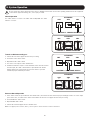
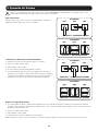
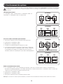
Do not operate the “SW2” switch unless the UPS is in BYPASS mode! Failure to follow the operating instructions for this equipment
could result in equipment damage, fire, severe injury or death!
NOFFONO
ON
O
I
ON
I
OFF
OFF OFFON
O
NOFFO
I
O
OFF
Normal Operation
The “SW1” Switch is closed/on. The “SW2” Switch is Open/Off. The “SW3”
Switch is closed/on.
Transfer to Maintenance Bypass
1. Transfer the UPS to the Bypass mode before proceeding.
2. Close/turn on the “SW2” switch.
3. Open/turn off the “SW3” switch.
4. The UPS is now ready for routine maintenance.
5. If further maintenance requires a total shutdown of the UPS and isolation
from the input, the “SW1” switch must be opened/turned off and the
battery supply to the UPS must be disconnected. Refer to your UPS
manual for proper shutdown procedures.
Return to Normal Operation
1. If the “SW1” switch was opened/turned off for maintenance, then follow the UPS manual for proper startup procedures. To restore input
power to the UPS, close/turn on the “SW1” switch. Make sure the UPS is in Bypass mode before proceeding.
2. Close/Turn-On the “SW3” switch.
3. Open/Turn-Off “SW2” switch.
4. Transfer the UPS from Bypass mode to Normal mode.
Note: To use Bypass position contacts, refer to your UPS system’s owner’s manual for connection instructions.
SW1
SW1
SW1
SW1
SW2
SW2
SUT40KMBP
SUT60KMBP
SW2
SW2
SUT40KMBP
SUT60KMBP
POSITION 1 - NORMAL OPERATION
POSITION 1 - NORMAL OPERATION
POSITION 2 - IN EXTERNAL BYPASS
POSITION 2 - IN EXTERNAL BYPASS
SW3
SW3
SW3
SW3

7
9. Maintenance
Before installing or maintaining this equipment, it is extremely important to read this manual and be sure that all equipment drawings
and schematics are reviewed and clearly understood. If there are any questions concerning this manual or any of the installation or
maintenance procedures and/or requirements, please contact a Tripp Lite representative before proceeding.
Inspection and maintenance should only be performed on equipment that has been de-energized and electrically isolated so that no
accidental contact can be made with energized parts.
9.1 Short Circuits and Overloads
Do not attempt to re-energize a switch after a short circuit or overload until the cause of the event has been identified and corrected.
Failure to correct the cause of the event may result in equipment damage, fire, severe injury or death.
Switches will normally prevent electrical damage except at the point where the short circuit occurred. High mechanical stress developed
by short circuit currents may cause damage to conductors, insulation or other components. After a fault, thorough inspection of the entire
system must be made to verify that there is no damage.
Switches which performed the short circuit interruption must be inspected for possible damage. Do not disassemble the switch or open the
switch trip unit.
Replace all damaged insulation materials, conductors and switches. It is recommended that the equipment be hipot tested prior to being
placed back in service.

8
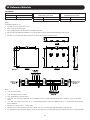
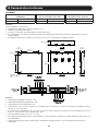
10. Reference Materials
Notes:
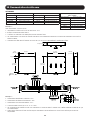
APPROXIMATE WEIGHT: 65 LB.
1. ASSEMBLY IS UL/CUL LISTED PER UL 1778.
2. NEMA 1 WALL MOUNT ENCLOSURE.
3. THE BOX AND TRIM ARE CONSTRUCTED OF GALVANIZED 16GA STEEL.
4. THE SWITCHES HAVE REMOVABLE HANDLES TO ALLOW THE TRIM COVER TO BE REMOVED FOR INTERNAL PANEL ACCESS.
5. THE PANEL IS TO BE MOUNTED THROUGH THE Ø0.53” HOLES IN THE BACK OF THE ENCLOSURE.
Notes:
1. “SW1” UPS INPUT SWITCH.
2. “SW2” MAINTENANCE BYPASS SWITCH.
3. “SW3” MAINTENANCE ISOLATION SWITCH.
4. GROUND LUG ACCEPTS (4) #14 - #2 AWG WIRES.
5. MECHANICAL LUGS USED FOR THE UTILITY INPUT AND THE OUTPUT TO LOAD HAVE THE SAME WIRE RANGE AS THE SWITCHES.
6. THIS DRAWING IS TO BE USED FOR ELECTRICAL PURPOSES ONLY AND DOES NOT REPRESENT THE ACTUAL MECHANICAL LAYOUT OF THE EQUIPMENT.
Torque Values for Slotted Head Terminals
Wire Size Torque Value
14-10 AWG 35 in•lb (3.9 N•m)
8 AWG 40 in•lb (4.5 N•m)
4-6 AWG 45 in•lb (5.1 N•m)
3-1/0 AWG 50 in•lb (5.6 N•m)
Torque Values for Socket Head Terminals
Hex Size Torque Value
3/16 in. 120 in•lb (13.6 N•m)
5/16 in. 275 in•lb (31.1 N•m)
3/8 in. 375 in•lb (42.4 N•m)
1/2 in. 500 in•lb (56.5 N•m)
Torque Values for Busbar Connections
Bolt Size Torque Value
#8 20 in•lb (2.2 N•m)
#10 30 in•lb (3.4 N•m)
1/4 in. 68 in•lb (7.7 N•m)
5/16 in. 10 ft•lb (13.6 N•m)
3/8 in. 20 ft•lb (27.1 N•m)
1/2 in. 50 ft•lb (67.8 N•m)
SUT40KMBP

9
10. Reference Materials
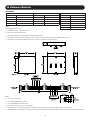
Notes:
APPROXIMATE WEIGHT: 85 LB.
1. ASSEMBLY IS UL/CUL LISTED PER UL 1778.
2. NEMA 1 WALL MOUNT ENCLOSURE.
3. THE BOX AND TRIM ARE CONSTRUCTED OF GALVANIZED 16GA STEEL.
4. THE SWITCHES HAVE REMOVABLE HANDLES TO ALLOW THE TRIM COVER TO BE REMOVED FOR INTERNAL PANEL ACCESS.
5. THE PANEL IS TO BE MOUNTED THROUGH THE Ø0.53” HOLES IN THE BACK OF THE ENCLOSURE.
Notes:
1. “SW1” UPS INPUT SWITCH.
2. “SW2” MAINTENANCE BYPASS SWITCH.
3. “SW3” MAINTENANCE ISOLATION SWITCH.
4. “SW2” AND “SW3” SWITCHES CONNECTED: 150A ASSEMBLIES USING (1) #2 AWG WIRE PER PHASE. 225A ASSEMBLIES USE (1) 1/0 WIRE PER
PHASE.
5. “SW1” AND “SW3” SWITCH LUGS ACCEPT (1) #6 - 300 MCM WIRE PER PHASE FOR 150A ASSEMBLIES AND (1) 2 - 600 MCM WIRE PER PHASE FOR
225A ASSEMBLIES.
6. GROUND LUG ACCEPTS (4) #14 - #2 AWG WIRES.
7. MECHANICAL LUGS USED FOR THE UTILITY INPUT AND THE OUTPUT TO LOAD HAVE THE SAME WIRE RANGE AS THE SWITCHES.
8. THIS DRAWING IS TO BE USED FOR ELECTRICAL PURPOSES ONLY AND DOES NOT REPRESENT THE ACTUAL MECHANICAL LAYOUT OF THE EQUIPMENT.
Torque Values for Switch Connections
Wire Size Torque Value
1/0-350 AWG 140 in•lb (16 N•m)
Torque Values for Input and
Output Lug Connections
Wire Size Torque Value
6-350 AWG 275 in•lb (31 N•m)
Torque Values for
Ground Lug Connections
Wire Size Torque Value
6-350 AWG 375 in•lb (42.36 N•m)
SUT60KMBP

10
11. Warranty
LIMITED WARRANTY AND EXCLUSIONS
Tripp Lite strives to produce quality products at reasonable prices. If you are not satisfied with our product because of a defect, we will repair or replace the defective part or parts
free of charge for a period of one year from the date of purchase. In the event you claim that the product contains a defect, simply notify Tripp Lite of the defect, and we will arrange
for repair or replacement. The sole and exclusive remedy against Tripp Lite relating in any way to a product defect shall be the repair or replacement of defective parts as provided
for under this LIMITED WARRANTY. No other remedy, including, but not limited to, incidental or consequential damages for lost profits, lost sales, injury to person or property, or any
other incidental or consequential loss, is available. This LIMITED WARRANTY shall not be deemed to have failed of its essential purpose so long as Tripp Lite is willing and able to
repair or replace defective parts in the manner prescribed in this LIMITED WARRANTY.
Certain integrated products, which are not manufactured by Tripp Lite, will be warranted by the applicable manufacturer. These warranties shall be between the
manufacturer and the user. Terms and conditions may vary. These integrated products include, but may not be limited to, the following products: Batteries, Inverters
and UPS Systems.
Any action for breach relating to the sale of a Tripp Lite product must be commenced within one year after the cause of action has been accrued.
THIS LIMITED WARRANTY IS IN LIEU OF ANY OTHER WARRANTY, EXPRESS OR IMPLIED, AND ALL SUCH WARRANTIES ARE EXCLUDED, INCLUDING, BUT NOT LIMITED TO, ANY
IMPLIED WARRANTY OF MERCHANTABILITY OR FITNESS FOR A PARTICULAR PURPOSE.
Tripp Lite has a policy of continuous improvement. Product specifications are subject to change without notice.
1111 W. 35th Street, Chicago, IL 60609 USA • www.tripplite.com/support

11
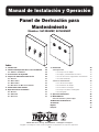
Panel de Derivación para
Mantenimiento
Modelos: SUT40KMBP, SUT60KMBP
Manual de Instalación y Operación
1111 W. 35th Street, Chicago, IL 60609 EE. UU. • www.tripplite.com/support
Copyright © 2018 Tripp Lite. Todas las marcas registradas son propiedad de sus respectivos propietarios.
Índice
1. Introducción 12
2. Información Importante Acerca de este Manual 12
2.1 Símbolos del Manual 12
3. Precauciones de Seguridad 12
4. Inspección al Recibir las Mercancías 13
4.1 General 13
4.2 Daño Visible 13
4.3 Daño Oculto 13
4.4 Devolución de Mercancía Dañada 13
5. Visión General del Sistema 13
6. Especificaciones del Sistema 13
6.1 Eléctrico 13
6.2 Ambiental 13
6.3 Generales 13
7. Instalación 14
7.1 Preparación 14
7.1.1 Inspección del Equipo 14
7.1.2 Equipo y Herramientas Necesarios 14
7.1.3 Precauciones de Seguridad en la Instalación 14
7.1.4 Almacenamiento 14
7.2 Pasos de Instalación 14
7.2.1 Ubicación del Equipo 14
7.2.2 Instalación del Equipo 14
7.2.3 Conexiones del Equipo 14
7.2.4 Inspección Antes de Energizado 15
7.2.5 Energizado 15
8. Operación del Sistema 16
9. Mantenimiento 17
9.1 Corto Circuitos y Sobrecargas 17
10. Materiales de Referencia 18
11. Garantía 20
English 1
Français 21

12
¡CONSERVE ESTAS INSTRUCCIONES!
Este manual contiene información importante que es necesaria durante la instalación y mantenimiento del sistema.
3. Precauciones de Seguridad
1. Introducción
2. Información Importante Acerca de este Manual
2.1 Símbolos del Manual
Advertencia:
Indica información proporcionada para proteger al usuario contra lesiones personales, riesgos de seguridad o posible daño al equipo.
Peligro Eléctrico:
Indica la existencia de un peligro eléctrico que dará lugar a lesiones personales o la muerte si no se siguen las instrucciones.
Importante:
Indica información proporcionada como una operación de instalación, instrucción o consejo, así como información general de
instalación y sistema.
A Tripp Lite desea agradecerle por elegir nuestro producto para las necesidades de su equipo. Sabemos que hay muchas opciones y
apreciamos la oportunidad de proveer a cada uno de nuestros clientes con los productos de más alta calidad fabricados en los Estados
Unidos. Todas nuestras soluciones son probadas en fábrica con los más altos estándares.
Soporte de ventas para las necesidades futuras de equipos o actualizaciones es proporcionado por nuestro personal de ventas regionales y
representantes calificados. Todas las preguntas técnicas y problemas de servicio se pueden dirigir a nuestra oficina principal visitando www.
tripplite.com/support.
Tripp Lite
www.tripplite.com
Soporte Técnico
www.tripplite.com/support
Antes de instalar o mantener este equipo, es muy importante leer este manual y asegúrese de que todos los dibujos y esquemas
del equipo sean revisados y entendidos. Si tiene alguna pregunta con respecto a este manual o cualquiera de los procedimientos de
instalación o mantenimiento y/o requisitos, póngase en contacto con un representante de Tripp Lite antes de proceder.
La información contenida en este manual no está diseñada para su uso como un manual de capacitación para el personal no
calificado.
Al instalar este equipo, siga siempre todos los reglamentos federales, estatales y locales aplicables para asegurar la instalación
correcta y segura.
Únicamente personas calificadas deben instalar o dar servicio a este equipo. Una persona calificada es alguien que tiene habilidades
y conocimientos relacionados con la construcción y operación de equipos e instalaciones eléctricas y ha recibido entrenamiento de
seguridad sobre los riesgos involucrados.
La instalación y el mantenimiento del equipo deben realizarse siempre con herramientas muy bien aisladas. También se recomienda
llevar botas y guantes de hule y utilizar tapetes aislantes para estar de pie cuando se trabaja en este equipo.
Siempre use protección para los ojos durante la instalación y mantenimiento de equipos de energía.
Para evitar lesiones personales, incluidas descargas eléctricas, quemaduras graves y posible muerte todas las alhajas, incluidas las
pulseras, anillos y relojes deben retirarse antes de instalar o dar mantenimiento a este equipo
Para la seguridad de los demás, nunca deje un gabinete o panel abierto sin supervisión.
Modificaciones al equipo sin la autorización de Tripp Lite podrían resultar en daño al equipo, lesiones personales o muerte.
Nunca trabaje con equipos de energía mientras esté energizado. Desenergice el equipo y bloquee toda la alimentación al equipo
antes de trabajar en el interior.
La inspección y mantenimiento deberán realizarse solamente en equipo que haya sido desenergizado y aislado eléctricamente de
modo que no pueda hacerse contacto accidental con partes energizadas.

13
4. Inspección al Recibir las Mercancías
5. Visión General del Sistema
4.1 General
Se han tomado cuidados y precauciones para garantizar que el sistema llegue seguro y en buenas condiciones. Sin embargo, una vez
recibido, debe inspeccionar todo el envío, incluyendo la caja de embalaje y las cajas, para verificar que no haya sufrido daños que puedan
haber ocurrido durante el transporte.
4.2 Daño Visible
Es responsabilidad de la persona que recibe el envío inventariar e inspeccionar completamente todos los materiales contra el conocimiento
de embarque o carta de porte INMEDIATAMENTE mientras que el representante de la compañía transportista todavía esté presente.
Asegúrese de que todos los elementos se contabilizan, incluyendo número de tarimas y cantidad de cajas. También tenga en cuenta
cualquier daño externo visible que pueda haber ocurrido durante el transporte. Haga todas las anotaciones aplicables en el recibo de
entrega antes de firmar y genere un informe de daños con el transportista.
4.3 Daño Oculto
Dentro de los 3 a 30 días de la recepción (dependiendo de la mensajería), desempaquete el sistema y compruebe para detectar daños
ocultos. Verifique los materiales recibidos contra la lista detallada para verificar que la cantidad y la condición sea completa y satisfactoria.
Tome nota de los daños en el embalaje interno. Luego, solicite una inspección por el transportista y presente un reclamo de daños ocultos.
Si faltaran partes o algún material, visite www.tripplite.com/support para presentar una reclamación.
Póngase en contacto con su compañía de envío para todos los daños del embarque. Tripp Lite no es responsable por daño
alguno durante el embarque.
4.4 Devolución de Mercancía Dañada
Si el equipo se daña y necesita devolverlo a Tripp Lite para reparación, un representante le dará instrucciones junto con un número de RMA
para agilizar la devolución.
Debe obtenerse un número de RMA antes de devolver el equipo a Tripp Lite.
El Panel de Derivación para Mantenimiento [MBP] de el SUT40KMBP y SUT60KMBP se utiliza en combinación con un Sistema de Respaldo
Ininterrumpible (UPS) para mantener la continuidad total de la energía a los circuitos de la carga conectada cuando se requiere la derivación
de los equipos UPS para la ejecución de mantenimiento y servicio regular.
Los MBPs de la Serie SUT40KMBP y SUT60KMBP están disponibles en un rango de capacidades de corriente de 150 a 225 amperes con
múltiples opciones disponibles de voltaje de entrada.
El MBP contiene tres switches de 4 polos.
Consulte siempre la etiqueta de clasificación del equipo para clasificaciones específicas de configuración. Las especificaciones y
clasificaciones del equipo en este documento representan el equipo típico y pueden variar del equipo proporcionado.
6.1 Eléctrico
Modelo SUT40KMBP SUT60KMBP
Voltaje 208Y / 120V CA, 3 Fases, 4 Hilos, más tierra 208Y / 120V CA, 3 Fases, 4 Hilos, más tierra
Frecuencia 60 Hz 60 Hz
Corriente 150A 225A
6.2 Ambiental
Modelo SUT40KMBP SUT60KMBP
Temperatura de Operación 0 °C a 40 °C [32 °F a 104 °F] 0 °C a 40 °C [32 °F a 104 °F]
Humedad Relativa 5% a 95%, sin condensación 5% a 95%, sin condensación
Altitud 0 a 2255 m [0 a 7400 pies] sobre el nivel del mar 0 a 2255 m [0 a 7400 pies] sobre el nivel del mar
6.3 General
Modelo SUT40KMBP SUT60KMBP
Dimensiones del
Gabinete (Al x An x Pr)
715 x 800 x 177 mm [28.13" x 31.5" x 6.98"] 800 x 978 x 150 mm [31.5" x 38.5" x 5.89"]
Peso 29.5 kg [65 lb] 38.5 kg [85 lb]
6. Especificaciones del Sistema

14
7. Instalación
7.1 Preparación
7.1.1 Inspección del Equipo
Retire el equipo del material de empaque e inspeccione para detectar daños de envío que se podrían haber escapado durante la recepción
de mercancías. Verifique que el sistema incluya todos los accesorios necesarios para la instalación.
7.1.2 Equipo y Herramientas Necesarios
• Herramienta correctamente aisladas
• Accesorios de instalación de tamaño y clasificación adecuados
7.1.3 Precauciones de Seguridad en la Instalación
¡Antes de proceder con la instalación del sistema, asegúrese de revisar y entender todas las PRECAUCIONES de seguridad en este manual!
ADVERTENCIA DE VOLTAJE DE CA
El voltaje de entrada y salida de este equipo puede ser de hasta 240 VCA. Asegúrese de leer y comprender este manual y
comprobar que todas las conexiones de CA estén correctas y apretadas apropiadamente. ¡Tenga mucho cuidado en la instalación y
mantenimiento del sistema!
7.1.4 Almacenamiento
Si el equipo no se puede instalar de inmediato, debe almacenarse en un lugar interior limpio y seco con temperatura uniforme y circulación
de aire suficiente para evitar la condensación. Si el equipo se debe almacenar por largo tiempo, debe estar cubierto para protegerlo del
polvo, suciedad y humedad.
7.2 Pasos de Instalación
Antes de instalar o mantener este sistema, es muy importante leer este manual y asegúrese de que todos los dibujos y esquemas
del sistema sean revisados y entendidos. Si tiene alguna pregunta con respecto a este manual o cualquiera de los procedimientos de
instalación o mantenimiento y/o requisitos, póngase en contacto con un representante de Tripp Lite antes de proceder.
7.2.1 Ubicación del Equipo
Este equipo está diseñado para ser instalado en un lugar de acceso restringido.
La ubicación permanente de los equipos debe ser sobre una superficie lisa y sólida de la pared. No coloque el equipo contra un techo que
no sea a prueba de fuego. Deje un espacio de 91 cm [3 pies] entre el techo y el equipo a menos que se proporcione un escudo a prueba de
fuego adecuado. Verifique también que la ubicación seleccionada brindará espacios de trabajo de acuerdo con el artículo 110.26 del Código
Eléctrico Nacional (NEC). También se deben revisar las condiciones ambientales de la ubicación seleccionada. Refiérase a la sección 6.2
Ambiental para consultar las especificaciones ambientales.
7.2.2 Instalación del Equipo
El equipo se debe fijar de modo confiable a la superficie de instalación. No dependa de tapones de madera clavados en agujeros en
mampostería, concreto, yeso o materiales similares según artículo 110.13 del Código Eléctrico Nacional (NEC). Asegure el equipo utilizando
los cuatro orificios de instalación de 8.6 mm [0.34”] de diámetro situados en la parte posterior del equipo. Dentro del equipo está incluido
un juego de planos del equipo para la configuración específica del equipo. Consulte los planos del equipo o tamaño y ubicación del orificio
de instalación. (Vea dibujos en la sección Materiales de Referencia.)
7.2.3 Conexiones del Equipo
Nunca trabaje con equipos de energía mientras esté energizado. Desenergice el equipo y bloquee toda la alimentación al equipo
antes de trabajar en el interior.
El panel superior e inferior del equipo es el área designada recomendada para el conducto de conducción de la conexión a tierra al equipo.
Todos los conductos deben colocarse para evitar interferencias con elementos estructurales y bus energizado. Dentro del equipo está
incluido un juego de planos para la configuración específica del equipo. Haga referencia a los dibujos de los equipos para localizar las áreas
de entrada de cable designado del equipo.
Todos los conductores deben dimensionarse para un ampacidad de 75 °C [167 °F]. Cuando se utiliza cable con rangos de
temperatura por encima de 75 °C [167 °F], deberá ser dimensionado basado en la ampacidad del cable especificado del cable a 75
°C [167 °F].
El equipo debe conectarse a tierra con el conductor de tamaño adecuado en conformidad con el artículo 250 del Código Eléctrico
Nacional (NEC). El conductor de tierra debe ser conectado con terminales al bus principal de tierra dentro del equipo.

15
7. Instalación
Retire las cubiertas del equipo según sea necesario para acceder a los puntos de conexión de entrada y salida. Donde los cables
entren o salgan del equipo o pasen a través de cualquier metal que tenga propiedades magnéticas, deberán estar arreglados de forma
que los conductores de neutro y fase estén agrupados entre sí y pasen por la misma abertura conforme artículo 300.20 del nacional
Código eléctrico (NEC). Al jalar el cable al equipo, tenga cuidado de no dañar cualquiera de los componentes internos y controlar el
cableado. Coloque los cables dentro de los equipos de modo que no estén sujetos a daños físicos y no estén forzados o presionados
permanentemente contra los bordes de las piezas de metal. Si los cables están en contacto con bordes afilados, coloque material protector
adecuado entre el cable y el borde del metal para proteger el aislamiento del cable.
Usando las herramientas apropiadas, pele una longitud de aislamiento de un extremo del cable lo suficiente para caber en toda la
longitud de la zapata de conexión mecánica para el punto de conexión señalado. Si utiliza conductores de aluminio, aplique un compuesto
antioxidante adecuado al aluminio desnudo. Inserte el conductor desnudo en la zapata para que el conductor desnudo llene toda la longitud
del cuerpo de la zapata mecánica. Apriete el tornillo prisionero en la zapata mecánica y apriete a los valores indicados en la Etiqueta de
Valores de Apriete en el equipo.
Consulte el dibujo Esquemático del Equipo para obtener información sobre las conexiones entre el Panel de Derivación para Mantenimiento,
el UPS y la carga crítica.
7.2.4 Inspección Antes del Energizado
La inspección y mantenimiento deberán realizarse solamente en equipo que haya sido desenergizado y aislado eléctricamente de
modo que no pueda hacerse contacto accidental con partes energizadas.
Antes de energizar el equipo, debe ser cuidadosamente inspeccionado.
1. Retire cualquier objeto extraño de dentro el equipo incluyendo herramientas, trozos de alambre u otros residuos.
2. Inspeccione visualmente el equipo para detectar cualquier daño que pueda haber ocurrido durante el proceso de instalación. Asegúrese
de inspeccionar todos los aisladores, barras colectoras y otros conductores. ¡No energice si se encuentra cualquier daño!
3. Verifique la orientación de fase del cable en todos los puntos de conexión.
4. Verifique que todas las conexiones de campo del cable se encuentren debidamente apretadas.
5. Haga funcionar manualmente todos los switches para verificar su operación adecuada.
6. Verifique que las conexiones a tierra del equipo estén terminadas correctamente.
7. Revise la secuencia de operación en derivación antes de accionar los switches.
8. Verifique que todas las cubiertas estén instaladas.
7.2.5 Energizado
¡Los voltajes peligrosos en equipos eléctricos pueden causar lesiones graves o la muerte!
Únicamente personas calificadas deben instalar o dar servicio a este equipo. Una persona calificada es alguien que tiene habilidades
y conocimientos relacionados con la construcción y operación de equipos e instalaciones eléctricas y ha recibido entrenamiento de
seguridad sobre los riesgos involucrados.
Asegure que la carga máxima continua no exceda el 80% de la clasificación del dispositivo de protección contra sobrecorriente
(switches y fusibles) empleado en distintos circuitos del motor, excepto aquellos circuitos que empleen breakers marcados como
adecuados para funcionamiento continuo al 100% de sus calificaciones.
Peligros extremos pueden existir cuando se energiza el equipo eléctrico. Tome todas las precauciones necesarias para proteger a personas y
bienes cuando se energiza este equipo. Antes de energizar el equipo, abra / apague todos los switches. Consulte el manual de la UPS para
los procedimientos apropiados de arranque.

16
8. Operación del Sistema
¡No utilice el switch "SW2" a menos que el UPS está en modo de DERIVACIÓN! ¡El incumplimiento de las instrucciones de este
equipo podría resultar en daño al equipo, fuego, lesiones graves o la muerte!
NOFFONO
ON
O
I
ON
I
OFF
OFF OFFON
O
NOFFO
I
O
OFF
Operación Normal
El Switch “SW1” está cerrado / encendido. El Switch “SW2” está Abierto /
Apagado. El Switch “SW3” está cerrado / encendido.
Transferencia a Derivación para Mantenimiento
1. Transfiera el UPS al modo de derivación antes de continuar.
2. Cierre / encienda el switch “SW2”.
3. Abra / apague el switch “SW3”.
4. El UPS está ahora listo para mantenimiento de rutina.
5. Si un mantenimiento adicional requiere un apagado total del UPS y el
aislamiento de la entrada, el switch "SW1" debe estar abierto / apagado y
la alimentación de batería al UPS debe estar desconectada. Consulte el
manual de su UPS para los procedimientos apropiados de apagado.
Regrese a la Operación Normal
1. Si el switch "SW1" fue abierto / apagado para mantenimiento, siga el manual del UPS para consultarlos procedimientos de arranque
apropiados. Para restaurar la alimentación de entrada al UPS, cierre / encienda el switch "SW1". Asegúrese de que el UPS está en modo
de Derivación antes de proceder.
2. Cierre / encienda el switch “SW3”.
3. Abra / Apague el switch “SW2”.
4. Transfiera el UPS de modo de Derivación a modo Normal.
Nota: Para utilizar los contactos de posición de derivación, consulte el manual del propietario del sistema UPS para obtener instrucciones de conexión.
SW1
SW1
SW1
SW1
SW2
SW2
SUT40KMBP
SUT60KMBP
SW2
SW2
SUT40KMBP
SUT60KMBP
POSICIÓN 1 - OPERACIÓN NORMAL
POSICIÓN 1 - OPERACIÓN NORMAL
POSICIÓN 2 - EN DERIVACIÓN EXTERNA
POSICIÓN 2 - EN DERIVACIÓN EXTERNA
SW3
SW3
SW3
SW3

17
9. Mantenimiento
Antes de instalar o mantener este equipo, es muy importante leer este manual y asegúrese de que todos los dibujos y esquemas
del equipo sean revisados y entendidos. Si tiene alguna pregunta con respecto a este manual o cualquiera de los procedimientos de
instalación o mantenimiento y/o requisitos, póngase en contacto con un representante de Tripp Lite antes de proceder.
La inspección y mantenimiento deberán realizarse solamente en equipo que haya sido desenergizado y aislado eléctricamente de
modo que no pueda hacerse contacto accidental con partes energizadas.
9.1 Corto Circuitos y Sobrecargas
No trate de volver a energizar un switch después de un corto circuito o sobrecarga hasta que haya sido identificada y corregida la
causa del evento. El no corregir la causa del evento, puede ocasionar daño al equipo, fuego, lesiones graves o la muerte.
Los switches normalmente evitarán daños eléctricos excepto en el punto donde se produjo el cortocircuito. La alta tensión mecánica
desarrollada por las corrientes de corto circuito puede causar daños a los conductores, aislamiento u otros componentes. Después de una
falla, debe inspeccionarse todo el sistema para verificar que no haya daño alguno.
Los switches que realizan la interrupción por corto circuito deben ser revisados para detectar posibles daños. No desarme el switch ni abra la
unidad de disparo del switch.
Reemplace todos los materiales de aislamiento, conductores e switches dañados. Se recomienda que el equipo sea probado antes de
ponerlo en servicio nuevamente.

18
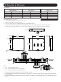
10. Materiales de Referencia
Notas:
PESO APROXIMATDO: 29.5 KG [65 LB]
1. EL CONJUNTO ESTÁ LISTADO POR UL/CUL SEGÚN UL 1778.
2. GABINETE NEMA 1 PARA INSTALACIÓN EN PARED.
3. LA CAJA Y LOS ACCESORIOS SON CONSTRUIDOS DE ACERO GALVANIZADO CALIBRE 16.
4. LOS SWITCHES TIENEN MANIJAS REMOVIBLES PARA PERMITIR QUE LA TAPA SE RETIRE PARA PERMITIR ACCESO AL PANEL INTERNO.
5. EL PANEL DEBE INSTALARSE A TRAVÉS DE LOS ORIFICIOS DE Ø 13.5 MM [0.53 PULG.] EN LA PARTE POSTERIOR DEL GABINETE.
Notas:
1. “SW1” – SWITCH DE ENTRADA DEL UPS.
2. “SW2” – SWITCH DE DERIVACIÓN PARA MANTENIMIENTO.
3. “SW3” – SWITCH DE AISLAMIENTO PARA MANTENIMIENTO.
4. LA ZAPATA PARA CONEXIÓN A TIERRA ACEPTA (4) CABLES #14 AWG ~ #2 AWG.
5. LAS ZAPATAS MECÁNICAS UTILIZADAS PARA LA ENTRADA DE LA RED PÚBLICA Y LA SALIDA A LA CARGA TIENEN LA MISMA ESPECIFICACIÓN DE CABLE
QUE LOS SWITCHES.
6. ESTOS DIBUJOS DEBEN SER UTILIZADOS PARA PROPÓSITOS ELÉCTRICOS SOLAMENTE Y NO REPRESENTAN LA DISPOSICIÓN MECÁNICA REAL DE LOS
EQUIPOS.
Valores de Apriete para Terminales de
Cabeza Ranurada
Tamaño de Cable Valor de Apriete
14 AWG ~ 10 AWG 35 in•lb (3.9 N•m)
8 AWG 40 in•lb (4.5 N•m)
4 AWG ~ 6 AWG 45 in•lb (5.1 N•m)
3-1/0 AWG 50 in•lb (5.6 N•m)
Valores de Apriete para Terminales de
Cabeza Hueca
Tamaño de Hex Valor de Apriete
3/16 pulg. 120 in•lb (13.6 N•m)
5/16 pulg. 275 in•lb (31.1 N•m)
3/8 pulg. 375 in•lb (42.4 N•m)
1/2 pulg. 500 in•lb (56.5 N•m)
Valores de Apriete para Conexiones de
la Barra de Bus
Tamaño de Tornillo Valor de Apriete
#8 20 in•lb (2.2 N•m)
#10 30 in•lb (3.4 N•m)
1/4 pulg. 68 in•lb (7.7 N•m)
5/16 pulg. 10 pies•lb (13.6 N•m)
3/8 pulg. 20 pies•lb (27.1 N•m)
1/2 pulg. 50 pies•lb (67.8 N•m)
SUT40KMBP
5.09 pulg. (129 mm)
2 pulg. (51 mm)
28.5 pulg.
(724 mm)
1.5 pulg.
(38 mm)
24.13 pulg.
(613 mm)
28.13 pulg.
(715 mm)
31.5 pulg.
(800 mm)
6.98 pulg.
(177 mm)
O0.53 pulg.
(O13.5 mm)

19
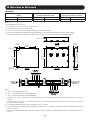
10. Materiales de Referencia
Notas:
PESO APROXIMATDO: 38.5 KG [85 LB]
1. EL CONJUNTO ESTÁ LISTADO POR UL/CUL SEGÚN UL 1778.
2. GABINETE NEMA 1 PARA INSTALACIÓN EN PARED.
3. LA CAJA Y LOS ACCESORIOS SON CONSTRUIDOS DE ACERO GALVANIZADO CALIBRE 16.
4. LOS SWITCHES TIENEN MANIJAS REMOVIBLES PARA PERMITIR QUE LA TAPA SE RETIRE PARA PERMITIR ACCESO AL PANEL INTERNO.
5. EL PANEL DEBE INSTALARSE A TRAVÉS DE LOS ORIFICIOS DE Ø 13.5 MM [0.53 PULG.] EN LA PARTE POSTERIOR DEL GABINETE.
Notas:
1. “SW1” – SWITCH DE ENTRADA DEL UPS.
2. “SW2” – SWITCH DE DERIVACIÓN PARA MANTENIMIENTO.
3. “SW3” – SWITCH DE AISLAMIENTO PARA MANTENIMIENTO.
4. SWITCHES “SW2” Y “SW3” CONECTADOS: CONJUNTOS DE 150A USANDO (1) CABLE #2 AWG POR FASE. CONJUNTOS DE 225A USAN (1) CABLE 1/0
POR FASE.
5. LAS ZAPATAS DEL SWITCH “SW1” Y “SW3” ACEPTAN (1) CABLE #6 - 300 MCM POR FASE PARA CONJUNTOS DE 150A Y (1) CABLE 2 - 600 MCM POR
FASE PARA CONJUNTOS DE 225A.
6. LA ZAPATA PARA CONEXIÓN A TIERRA ACEPTA (4) CABLES #14 AWG ~ #2 AWG.
7. LAS ZAPATAS MECÁNICAS UTILIZADAS PARA LA ENTRADA DE LA RED PÚBLICA Y LA SALIDA A LA CARGA TIENEN LA MISMA ESPECIFICACIÓN DE CABLE
QUE LOS SWITCHES.
8. ESTOS DIBUJOS DEBEN SER UTILIZADOS PARA PROPÓSITOS ELÉCTRICOS SOLAMENTE Y NO REPRESENTAN LA DISPOSICIÓN MECÁNICA REAL DE LOS
EQUIPOS.
Valores de Apriete para las Conexiones de
Switch
Tamaño de Cable Valor de Apriete
1/0-350 AWG 140 in•lb (16 N•m)
Valores de Apriete para Conexiones de
Zapata de Entrada y Salida
Tamaño de Cable Valor de Apriete
6-350 AWG 275 in•lb (31 N•m)
Valores de Apriete para
Conexiones de Zapata para Tierra
Tamaño de Cable Valor de Apriete
6-350 AWG 375 in•lb (42.36 N•m)
SUT60KMBP
5.89 pulg. (150 mm)
2 pulg. (51 mm)
28.5 pulg.
(724 mm)
5 pulg.
(127 mm)
27.5 pulg.
(699 mm)
31.5 pulg.
(800 mm)
38.5 pulg.
(978 mm)
7.8 pulg.
(198 mm)
O0.53 pulg.
(O13.5 mm)

20
11. Garantía
GARANTÍA LIMITADA Y EXCLUSIONES
Tripp Lite se esfuerza por producir productos de calidad a precios razonables. Si no estás satisfecho con nuestro producto debido a un defecto, repararemos o reemplazaremos
la parte o partes defectuosas sin cargo por un período de un año a partir de la fecha de compra. En el caso de que afirme que el producto contiene un defecto, simplemente
notifique a Tripp Lite del defecto y haremos los arreglos para la reparación o el reemplazo. El único y exclusivo recurso contra Tripp Lite relacionado en algún modo a un defecto del
producto será la reparación o sustitución de las piezas defectuosas según lo estipulado en esta GARANTÍA LIMITADA. No está disponible otro recurso, incluyendo pero no limitados
a, los daños incidentales o consecuentes por pérdida de beneficios, pérdida de ventas, daños a personas o propiedades, o cualquier otra pérdida incidental o consecuente. No
se considerará que esta GARANTÍA LIMITADA ha fallado en su propósito esencial siempre que Tripp Lite está dispuesto y pueda reparar o reemplazar las piezas defectuosas de la
manera prescrita en esta GARANTÍA LIMITADA.
Ciertos productos integrados, que no son fabricados por Tripp Lite, estarán garantizadas por el fabricante aplicable. Estas garantías serán entre el fabricante y
el usuario. Los términos y condiciones pueden variar. Estos productos integrados incluyen, pero pueden no estar limitados a, los siguientes productos: Baterías,
Inversores y Sistemas UPS.
Cualquier acción por infracción relativa a la venta de un producto Tripp Lite debe comenzar dentro de un año después de que la causa de acción haya sido acumulada.
ESTA GARANTÍA LIMITADA REEMPLAZA CUALQUIER OTRA GARANTÍA, EXPRESA O IMPLÍCITA Y TODAS ESAS GARANTÍAS QUEDAN EXCLUIDAS, INCLUYENDO, SIN LIMITARSE A,
CUALQUIER GARANTÍA IMPLÍCITA DE COMERCIABILIDAD O IDONEIDAD PARA UN PROPÓSITO PARTICULAR.
Tripp Lite tiene una política de mejora continua. Las especificaciones del producto están sujetas a cambios sin previo aviso.
1111 W. 35th Street, Chicago, IL 60609 EE. UU. • www.tripplite.com/support
La page est en cours de chargement...
La page est en cours de chargement...
La page est en cours de chargement...
La page est en cours de chargement...
La page est en cours de chargement...
La page est en cours de chargement...
La page est en cours de chargement...
La page est en cours de chargement...
La page est en cours de chargement...
La page est en cours de chargement...
La page est en cours de chargement...
La page est en cours de chargement...
-
 1
1
-
 2
2
-
 3
3
-
 4
4
-
 5
5
-
 6
6
-
 7
7
-
 8
8
-
 9
9
-
 10
10
-
 11
11
-
 12
12
-
 13
13
-
 14
14
-
 15
15
-
 16
16
-
 17
17
-
 18
18
-
 19
19
-
 20
20
-
 21
21
-
 22
22
-
 23
23
-
 24
24
-
 25
25
-
 26
26
-
 27
27
-
 28
28
-
 29
29
-
 30
30
-
 31
31
-
 32
32


Tripp Lite SUT40KMBP & SUT60KMBP Mode d'emploi
- Taper
- Mode d'emploi
dans d''autres langues
Documents connexes
-
Tripp Lite Maintenance Bypass Panel Mode d'emploi
-
Tripp Lite SUT20KMBP & SUT30KMBP Mode d'emploi
-
-
-
-
-
-
Tripp Lite SmartOnline 208V SV-Series 3-Phase Modular UPS Systems Le manuel du propriétaire
-
-