
1
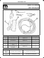
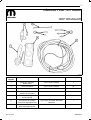
HARDTOPWIRING
JEEPWRANGLER
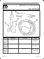
CallOutDescriptionPartsQuantity
1DualOutputWasherPumpSuppliedinKit1
2TieStrapSuppliedinkit10
3WireSplicingKitSuppliedinkit1
4WasherHoseConnectorKitSuppliedinkit1
5OverlayHarnessSuppliedinkit1
6HVACControlswithRear
Defrost
Suppliedinkit82212859only1
7MultiFunctionSwitchwith
RearWiper
Suppliedinkit1
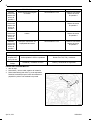
TOOLSREQUIRED
7mmand10mm
Socketsand
Ratchet
TrimStickC4755orequivalentTorxBitsT45,T50andDriver
Phillips
ScrewdriverSolderingIronandSolderWireStrippersandCrimpingTool
Apr01,2011K6861300
www.mopar.com

2
PROCEDURESTEPS:
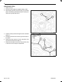
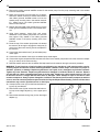
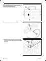
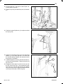
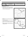
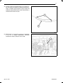
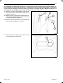
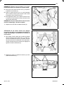
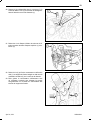
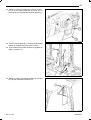
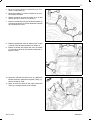
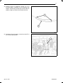
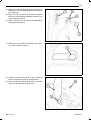
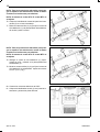
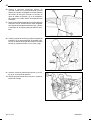
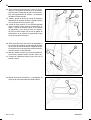
1.Raisethehood.
2.Disconnectandisolatethenegativebatterycable.
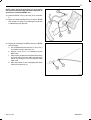
3.Removethegrommet(2)fromthehole(1)inthedash
panel.Discardthegrommetbecausetheoverlayhar
nesshasagrommetbuiltintoit.
4.Installtheoverlayharnessthroughtheholeinthedash
panel(3).
5.Instalthegrommetontheharness(4)intotheholeun
tilitseats.
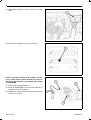
6.Routethewiringharness(2)totherightsideofthe
cowlandsecurewithatiestrap(1).
7.Routetherearwasherhose(5)tothewasherpump
intheleftfrontoftheenginecompartment.
Apr01,2011K6861300

3
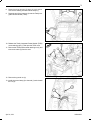
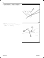
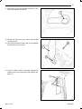
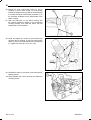
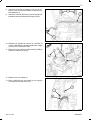
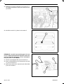
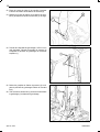
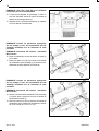
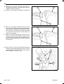
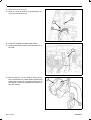
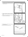
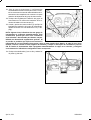
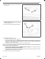
8.Routethewiringharness(2)alongthecowlandse
cureittotheexistingharnesswithtiestraps(1).
9.Routetheendoftheharness(3)neartheTotallyInte
gratedPowerModule(TIPM).
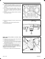
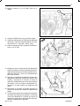
10.ReleasetheTotallyIntegratedPowerModule(TIPM)
coverretainingclips(1)andopentheTIPMcover.
11.RemovetheTIPMpositivecableretainingnut(2)and
removethecable(4)fromthestud.
12.Removethegroundnut(2).
13.Installthegroundstrap(3)tothestud(1)andreinstall
thenut(2).
Apr01,2011K6861300

4
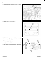
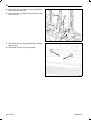
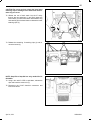
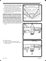
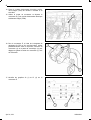
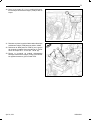
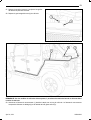
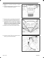
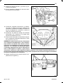
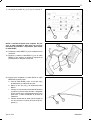
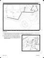
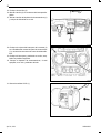
14.PositiontheTIPMtoaccesstheunderside.
15.ReleasetheconnectorlatchandremoveconnectorE
(1)fromtheTIPM.
16.ForconnectorE,usingtrimstickC4755orequiva
lent,carefullyinsertbetweenconnectorcoverlatch(2)
andthelocktab(3)torelease,andslidetheconnector
housing(1)offtheconnector.
17.Identifypins32(1)and27(2)onconnectorE.
Apr01,2011K6861300

5
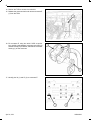
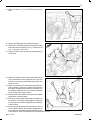
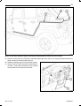
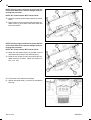
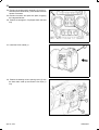
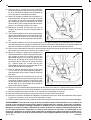
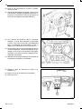
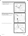
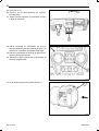
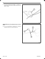
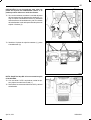
NOTE:Cavity32maybepopulated.Ifso,theexisting
wiremustberemovedusingaterminalremovalkit,or
equivalenttoinstalltheDB/WTwire.
18.InserttheDB/WTwire(1)intocavity32onconnector
E.
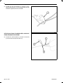
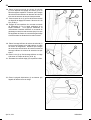
19.SpliceandsoldertheBR/LGwire(3)intotheBR/DB
wire(2)thatisincavity27byfollowingtheprocedure
inStep#20throughStep#23.
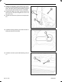
20.Preparetocrimp/splicetheBR/LGwiretotheBR/DB
wireasfollows:
a.CuttheBR/DBwireandremove13mm(0.5in.)
ofinsulationoneachsideofthecut.
b.Remove13mm(0.5in.)ofinsulationfromthe
BR/LGwire.
c.Placeapieceofadhesivelinedheatshrinktubing
(2)ononesideofthewire.Makesurethetubing
willbelongenoughtocoverandsealtheentire
repairarea.
d.Placethestrandsofwireoverlappingeachother
insideofthespliceclip(1).
Apr01,2011K6861300

6
21.Usingcrimpingtool(1),Mopar®p/n05019912AAor
equivalent,crimpthespliceclipandwirestogether.
CAUTION:Donotuseacidcoresolder.
22.Usingasoldertool(3),soldertheconnection(2)to
getherwithrosincoresolder(1).
Apr01,2011K6861300

7
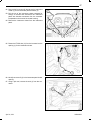
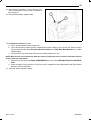
23.Centertheheatshrinktubing(2)overthesolderjoint
andheatusingaheatgun.Heatthejointuntilthetub
ingistightlysealedandsealant(1)comesoutofboth
endsofthetubing.
24.ReassembletheconnectorandinstallconnectorE(1)
totheTIPMandsecurethelatch.
Apr01,2011K6861300

8
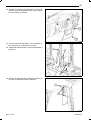
25.DisconnectthelatchandremoveconnectorG(1)from
theTIPM.
26.Identifycavity31(1)inconnectorG.
NOTE:Cavity31maybepopulated.Ifso,theexisting
wiremustberemovedusingaterminalremovalkit,or
equivalenttoinstalltheBR/DBwire
27.Removetheseal(2)fromconnectorG.
28.InstalltheBR/DBwire(1)fromtheharnessintocavity
31(3)inconnectorG.
29.Afterinstallingtheterminal,installtheseal(2)back
intotheconnector.
Apr01,2011K6861300

9
30.InstallconnectorG(1)totheTIPMandsecurethe
latch.
31.PositiontheTIPMbackintoitsoriginalposition.
32.PositiontheTIPMpositivecable(4)ontothemounting
studandinstalltheretainingnut(2).Tightenthenut
to911N∙m(80100in.lbs.).
33.ClosetheTIPMcoverandsnaptheretainingclips(1)
totheTIPM.
34.Siphonthewasherfluidfromthewasherreservoir(6)
ontheforwardendofthecomponenttray(3)onthe
leftsideoftheenginecompartmentintoacleancon
tainerforreuse.
35.Reachintothewellofthecomponenttraydirectlybe
hindthewasherreservoirtoaccessanddisconnect
theenginecompartmentwireharnessconnectorfrom
thewasherpump/motorunit(1)connectorreceptacle
(2)onthetopofthemotorhousing.
36.Disconnectthefrontwasherhose(4)fromthewasher
pump/motorunitoutletnipple.
37.Pullthetopofthewasherpump/motorunitawayfrom
thereservoirfarenoughtodisengagethesnappost
(5)onthetopofthemotorhousingfromthereceptacle
inthereservoir.
38.Pullthewasherpump/motorunitstraightupandout
ofthewasherreservoirfarenoughtodisengagethe
inletnipplefromtherubbergrommetseal/filterscreen
inthereservoir.Caremustbetakennottodamagethereservoir.
Apr01,2011K6861300

10
39.Removetherubbergrommetseal/filterscreenforthewasherpumpfromthepumpmountingholeinthewasher
reservoiranddiscard.
40.Reachintothewellofthecomponenttray(3)directly
behindthewasherreservoirtoaccessandInstalla
newrubbergrommetseal/filterscreenunitintothe
washerpumpmountingholeinthewasherreservoir
(6).Alwaysuseanewrubbergrommetseal/filter
screenonthereservoir.
41.Positiontheinletnippleofthewasherpump(1)tothe
rubbergrommetseal/filterscreeninthewasherreser
voir.
42.Usinghandpressure,pressfirmlyandevenly
downwardonthewasherpump/motorunituntilthe
inletnippleisfullyseatedintherubbergrommet
seal/filterscreeninthepumpmountingholeofthe
reservoir.
43.Pressthetopofthewasherpump/motorunittoward
thereservoirfarenoughtoengagethesnappost(5)
onthetopofthemotorhousingintothereceptaclein
thereservoir.
44.Connecttherearwasherhose(7)tothebarbedpump
outletnipple.
45.Connectthefrontwasherhose(4)tothebarbedpumpoutletnipple.
46.Connecttheenginecompartmentwireharnessconnectorforthewasherpump/motorunittotheconnectorrecepta
cle(2)onthetopofthemotorhousing.
47.Refillthewasherreservoirwiththewasherfluidsiphonedfromthereservoirduringtheremovalprocedure.
WARNING:Toavoidseriousorfatalinjuryduringandfollowinganyseatbeltorchildrestraintanchorservice,
carefullyinspectallseatbelts,buckles,mountinghardware,retractors,tetherstraps,andanchorsforproperin
stallation,operation,ordamage.Replaceanybeltthatiscut,frayed,ortorn.Straightenanybeltthatistwisted.
Tightenanyloosefasteners.Replaceanybeltthathasadamagedorineffectivebuckleorretractor.Replace
anybeltthathasabentordamagedlatchplateoranchorplate.Replaceanychildrestraintanchorortheunit
towhichtheanchorisintegralthathasbeenbentordamaged.Neverattempttorepairaseatbeltorchild
restraintcomponent.Alwaysreplacedamagedorineffectiveseatbeltandchildrestraintcomponentswiththe
correct,newandunusedreplacementpartslistedintheChryslerMopar®PartsCatalog.Failuretofollowthese
instructionsmayresultinpossibleseriousorfatalinjury.
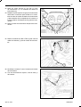
48.Unsnapthetrimcover(4)fromthefrontseatbeltturn
ingloop(2)anddiscard.
49.Removethescrew(3)thatsecurestheseatbeltturn
inglooptotheheightadjuster(1)ontheuppersport
bar.
50.Removetheseatbeltturningloop(2)fromtheheight
adjuster(1).
Apr01,2011K6861300

11
51.Removetheclipfromtheseatreclininghandle(1)and
removethehandlefromtheseat.
52.Positiontheseatcover(2)toexposetheseatbelt
mountingbolt(3).
53.Removetheseatbeltmountingbolt(3)andseparate
theseatbelt(1)fromtheseat.
54.UsingTrimStickC4755orequivalent,separatethe
retainingclips(2)andremovetheupperBpillartrim
panel(1).
Apr01,2011K6861300

12
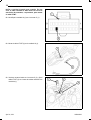
55.Removethepushpinfasteners(3)andseparatethe
lowerBpillartrimpanel(2).
56.Pulltheseatbelt(1)throughtheslotinthetrim(2)and
removethetrim.
57.Removethepushpin(1)andseparatethecowlpanel
retainingclips.
58.Removethecowltrim(2)fromthevehicle.
Apr01,2011K6861300

13
NOTE:Ontwodoormodelsitmaybenecessarytolooptheharnessattherearofthevehicle.
59.Routetheoverlayharness(1)behindthecarpetalongthelengthofthevehicle.Theoverlayharnessconsistsofthe
wiringharness(2)andrearwasherhose(3).
60.Positionthesteeringwheelintothefulldownposition.
61.UsingTrimStickC4755orequivalent,releasetheup
perclips(1)androtatethesteeringcolumnopening
cover(2)downandremovefromlowertabs.
Apr01,2011K6861300

14
62.Ifequippedwithpowerwindows,usingatrimstick
C4755orasuitableflatbladedtool,gentlyprythe
switchassembly(2)awayfromtheinstrumentcluster
bezel(1).
63.Forvehicleswithoutpowerwindows,usingatrim
stickC4755orasuitableflatbladedtool,gentlypry
thestoragebinassemblyawayfromthebezeland
remove.
64.Disconnecttheswitchassemblyelectricalconnector
andremovetheswitch.
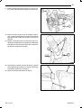
65.Removethestoragebinmatandremovethetop
screw(1).
66.Removethescrew(2)fromtheswitchopening.
67.Removethescrews(3).
NOTE:Performthisprocedureonthetwocenter
HVACoutlets.
68.Rotatethelouversoftheairoutlet(1)beingserviced
totheelevenoclockposition(2).
69.Placeasmallscrewdriver(4)orequivalentthroughthe
squareopening(5)insideoftheairoutlet,locatedat
thetwelvethirtyposition(3).
70.Carefullyprytheretainingtabtowardthecenterofthe
airoutletandrotatetheoutletcounterclockwise.
NOTE:Ifthefoamsealontheairoutletisdeformedor
damaged,thesealmustbereplaced.
71.Removetheairoutletfromtheinstrumentpanel(6).
Apr01,2011K6861300

15
CAUTION:Donotusetoolstoreleasethelowerbezel
retainingclipsordamagetothebezelandreinforc
mentringcanoccur.
72.WithouttheuseoftoolsreachintotheIPcavity
throughtheventopenings(1)andfirmlygraspthe
lowerbezel(2)behindthebezelreinforcementring
andcarefullypullthebezelbacktoreleasethelower
retainingclips(3).
73.Releasetheremaining13retainingclips(1)andre
movethebezel(2).
NOTE:Step#74toStep#81areonlyneededforkit
82212859.
74.UsingatrimstickC4755orequivalent,releasethe
clipsandlowerthecentertrim(1).
75.DisconnecttheHVACelectricalconnectorsand
removethebezel.
Apr01,2011K6861300

16
NOTE:Taketheproperprecautionstoprotecttheface
ofthecenterbezelfromcosmeticdamagewhileper
formingthisprocedure.
NOTE:ATCcontrolshown.MTCcontrolsimilar.
76.Placetheinstrumentpanelcenterbezel(3)onawork
bench.
77.Removethefourscrews(2and4)thatsecuretheA/C
heatercontrol(1)tothebackofthecenterbezeland
removethecontrol.
NOTE:Taketheproperprecautionstoprotecttheface
ofthecenterbezelfromcosmeticdamagewhileper
formingthisprocedure.
NOTE:ATCcontrolshown.MTCcontrolsimilar.
78.ObtaintheA/Cheatercontrol(1)providedinthekit
andinstallontothebackofthecenterbezel(3).
79.Installthefourscrews(2and4)thatsecuretheA/C
heatercontroltothebezel.Tightenthescrewsto2
N∙m(17in.lbs.).
80.ConnecttheHVACelectricalconnectors.
81.Positionthecenterbezel(1)ontotheI/Pandseatthe
clipsfully.
Apr01,2011K6861300

17
82.Removethefourscrews(3)thatsecuretheinstrument
cluster(1)totheinstrumentpanelarmature(2).
83.Pullthetopoftheinstrumentclusterrearwardfar
enoughtoaccessanddisconnecttheinstrument
panelwireharnessconnectorsfromtheconnector
receptaclesonthebackoftheclusterhousing.
84.Removetheinstrumentclusterfromtheinstrument
panel.
85.RoutetheVT/WHwire(2)fromtheharnessintothe
opening(1)fortheinstrumentcluster.
86.IdentifyconnectorC(2)intheinstrumentpanelcluster
opening.
87.Usingapicktool,removetheseal(1)fromthecon
nector.
Apr01,2011K6861300

18
NOTE:Cavity18maybepopulated.Ifso,theexisting
wiremustberemovedusingaterminalremovalkit,or
equivalenttoinstalltheVT/WTwire.
88.Identifycavity18(2)inconnectorC(1).
89.InstalltheVT/WTwire(2)intocavity18(1).
90.ReinstallthesealinconnectorC(3)andsecurethe
VT/WTwire(2)totheexistingwiringharnessusinga
tiestrap(1).
Apr01,2011K6861300

19
91.Removescrewsfromthelowercolumnshroudandre
moveboththeupper(1)andlower(2)shrouds.
92.Removethescrew(2)thatsecurestheright
multifunctionswitch(1)tothemountingbracket
integraltotherightsideoftheclockspring(3)onthe
steeringcolumn.
93.Slidetheswitchawayfromtheclockspringfarenough
todisengagetheslidetabsontheswitchhousingfrom
thechannelformationsinthemountingbracket.
94.Disconnectthejumperwireharnessconnector(1)
fromtheconnectorreceptacleontheinboardendof
therightmultifunctionswitch(2).
95.Removetheswitchfromtheclockspring(3).
Apr01,2011K6861300

20
96.Positiontherightmultifunctionswitch(2)thatis
includedinthekitcloseenoughtothemounting
bracket(3)integraltotherightsideoftheclockspring
toconnectthejumperwireharnessconnector(1)to
theconnectorreceptacleontheinboardsideofthe
switchhousing.
97.Aligntheslidetabsontheswitchhousingwith
thechannelformationsintegraltotheclockspring
mountingbracket,thenslidetheswitchintothe
bracketuntilitisfirmlyseated.
98.Installandtightenthescrew(2)thatsecuresthe
mountingtabonthebackoftherightmultifunction
switch(1)tothemountingbracketontheclockspring
(3).Tightenthescrewto1N∙m(10in.lbs.).
99.Reinstalltheupper(1)andlower(2)shroudsontothe
steeringcolumn.
100.Snaptogetherthecolumnshroudsandinstallthe
mountingscrews.
Apr01,2011K6861300
La page est en cours de chargement...
La page est en cours de chargement...
La page est en cours de chargement...
La page est en cours de chargement...
La page est en cours de chargement...
La page est en cours de chargement...
La page est en cours de chargement...
La page est en cours de chargement...
La page est en cours de chargement...
La page est en cours de chargement...
La page est en cours de chargement...
La page est en cours de chargement...
La page est en cours de chargement...
La page est en cours de chargement...
La page est en cours de chargement...
La page est en cours de chargement...
La page est en cours de chargement...
La page est en cours de chargement...
La page est en cours de chargement...
La page est en cours de chargement...
La page est en cours de chargement...
La page est en cours de chargement...
La page est en cours de chargement...
La page est en cours de chargement...
La page est en cours de chargement...
La page est en cours de chargement...
La page est en cours de chargement...
La page est en cours de chargement...
La page est en cours de chargement...
La page est en cours de chargement...
La page est en cours de chargement...
La page est en cours de chargement...
La page est en cours de chargement...
La page est en cours de chargement...
La page est en cours de chargement...
La page est en cours de chargement...
La page est en cours de chargement...
La page est en cours de chargement...
La page est en cours de chargement...
La page est en cours de chargement...
La page est en cours de chargement...
La page est en cours de chargement...
La page est en cours de chargement...
La page est en cours de chargement...
La page est en cours de chargement...
La page est en cours de chargement...
La page est en cours de chargement...
La page est en cours de chargement...
La page est en cours de chargement...
La page est en cours de chargement...
La page est en cours de chargement...
La page est en cours de chargement...
La page est en cours de chargement...
La page est en cours de chargement...
La page est en cours de chargement...
-
 1
1
-
 2
2
-
 3
3
-
 4
4
-
 5
5
-
 6
6
-
 7
7
-
 8
8
-
 9
9
-
 10
10
-
 11
11
-
 12
12
-
 13
13
-
 14
14
-
 15
15
-
 16
16
-
 17
17
-
 18
18
-
 19
19
-
 20
20
-
 21
21
-
 22
22
-
 23
23
-
 24
24
-
 25
25
-
 26
26
-
 27
27
-
 28
28
-
 29
29
-
 30
30
-
 31
31
-
 32
32
-
 33
33
-
 34
34
-
 35
35
-
 36
36
-
 37
37
-
 38
38
-
 39
39
-
 40
40
-
 41
41
-
 42
42
-
 43
43
-
 44
44
-
 45
45
-
 46
46
-
 47
47
-
 48
48
-
 49
49
-
 50
50
-
 51
51
-
 52
52
-
 53
53
-
 54
54
-
 55
55
-
 56
56
-
 57
57
-
 58
58
-
 59
59
-
 60
60
-
 61
61
-
 62
62
-
 63
63
-
 64
64
-
 65
65
-
 66
66
-
 67
67
-
 68
68
-
 69
69
-
 70
70
-
 71
71
-
 72
72
-
 73
73
-
 74
74
-
 75
75


Mopar 82214392 Guide d'installation
- Taper
- Guide d'installation
- Ce manuel convient également à
dans d''autres langues
- English: Mopar 82214392 Installation guide
- español: Mopar 82214392 Guía de instalación
Documents connexes
-
Mopar 82215385AC Guide d'installation
-
-
-
-
-
-
-
-
-
