Bosch GDR 12V 2 Manuel utilisateur
- Catégorie
- Perceuses mixtes sans fil
- Taper
- Manuel utilisateur

IMPORTANT: IMPORTANT : IMPORTANTE:
Read Before Using Lire avant usage Leer antes de usar
Operating/Safety Instructions
Consignes de fonctionnement/sécurité
Instrucciones de funcionamiento y seguridad
22612
22614
22618
23609
23612
23614
23618
For English Version Version française Versión en español
See page 2 Voir page 19 Ver la página 36
1-877-BOSCH99 (1-877-267-2499) www.boschtools.com
Call Toll Free for
Consumer Information
&Service Locations
Pour obtenir des informations
et les adresses de nos centres
de service après-vente,
appelez ce numéro gratuit
Llame gratis para
obtener información
para el consumidor y
ubicaciones de servicio
BM 2609140358 12-05 12/6/05 3:28 PM Page 1
Downloaded from www.Manualslib.com manuals search engine

-2-
Work area safety
Keep work area clean and well lit.
Cluttered or dark areas invite accidents.
Do not operate power tools in explosive
atmospheres, such as in the presence of
flammable liquids, gases or dust. Power
tools create sparks which may ignite the dust
or fumes.
Keep children and bystanders away while
operating a power tool. Distractions can
cause you to lose control.
Electrical safety
Power tool plugs must match the outlet.
Never modify the plug in any way. Do not
use any adapter plugs with earthed
(grounded) power tools. Unmodified plugs
and matching outlets will reduce risk of
electric shock.
Avoid body contact with earthed or
grounded surfaces such as pipes,
radiators, ranges and refrigerators. There
is an increased risk of electric shock if your
body is earthed or grounded.
Do not expose power tools to rain or wet
conditions. Water entering a power tool will
increase the risk of electric shock.
Do not abuse the cord. Never use the cord
for carrying, pulling or unplugging the
power tool. Keep cord away from heat, oil,
sharp edges or moving parts. Damaged or
entangled cords increase the risk of electric
shock.
When operating a power tool outdoors,
use an extension cord suitable for
outdoor use. Use of a cord suitable for
outdoor use reduces the risk of electric
shock.
Do not use AC only rated tools with a DC
power supply. While the tool may appear to
work, the electrical components of the AC
rated tool are likely to fail and create a
hazard to the operator.
If operating the power tool in damp
locations is unavoidable a Ground Fault
Circuit Interrupter (GFCI) must be used to
supply the power to your tool. GFCI and
personal protection devices like electrician’s
rubber gloves and footwear will further
enhance your personal safety.
Personal safety
Stay alert, watch what you are doing and
use common sense when operating a
power tool. Do not use a power tool while
you are tired or under the influence of
drugs, alcohol or medication. Amoment of
inattention while operating power tools may
result in serious personal injury.
Use safety equipment. Always wear eye
protection. Safety equipment such as dust
mask, non-skid safety shoes, hard hat, or
hearing protection used for appropriate
conditions will reduce personal injuries.
Avoid accidental starting. Ensure the
switch is in the off-position before
plugging in. Carrying power tools with your
finger on the switch or plugging in power
tools that have the switch on invites
accidents.
Remove any adjusting key or wrench
before turning the power tool on. Awrench
or a key left attached to a rotating part of the
power tool may result in personal injury.
Do not overreach. Keep proper footing
and balance at all times. This enables
better control of the power tool in unexpected
situations.
Dress properly. Do not wear loose
clothing or jewelry. Keep your hair,
clothing and gloves away from moving
parts. Loose clothes, jewelry or long hair can
be caught in moving parts.
If devices are provided for the connection
of dust extraction and collection facilities,
ensure these are connected and properly
used. Use of these devices can reduce dust-
related hazards.
Read all instructions. Failure to follow all instructions listed below may
result in electric shock, fire and/or serious injury. The term “power tool”
in all of the warnings listed below refers to your mains-operated (corded) power tool or
battery-operated (cordless) power tool.
SAVE THESE INSTRUCTIONS
!
WARNING
General Safety Rules
BM 2609140358 12-05 12/6/05 3:28 PM Page 2
Downloaded from www.Manualslib.com manuals search engine

-3-
Keep handles dry, clean and free from oil
and grease. Slippery hands cannot safely
control the power tool.
Power tool use and care
Do not force the power tool. Use the
correct power tool for your application.
The correct power tool will do the job better
and safer at the rate for which it was
designed.
Do not use the power tool if the switch
does not turn it on and off. Any power tool
that cannot be controlled with the switch is
dangerous and must be repaired.
Disconnect the plug from the power
source and/or the battery pack from the
power tool before making any
adjustments, changing accessories, or
storing power tools. Such preventive safety
measures reduce the risk of starting the
power tool accidentally.
Store idle power tools out of the reach of
children and do not allow persons
unfamiliar with the power tool or these
instructions to operate the power tool.
Power tools are dangerous in the hands of
untrained users.
Maintain power tools. Check for
misalignment or binding of moving parts,
breakage of parts and any other condition
that may affect the power tools operation.
If damaged, have the power tool repaired
before use. Many accidents are caused by
poorly maintained power tools.
Keep cutting tools sharp and clean.
Properly maintained cutting tools with sharp
cutting edges are less likely to bind and are
easier to control.
Use the power tool, accessories and tool
bits etc., in accordance with these
instructions and in the manner intended
for the particular type of power tool,
taking into account the working
conditions and the work to be performed.
Use of the power tool for operations different
from those intended could result in a
hazardous situation.
Use clamps or other practical way to
secure and support the workpiece to a
stable platform. Holding the work by hand
oragainst your body is unstable and may
lead to loss of control.
Battery tool use and care
Ensure the switch is in the off position
before inserting battery pack. Inserting the
battery pack into power tools that have the
switch on invites accidents.
Recharge only with the charger specified
by the manufacturer. Acharger that is
suitable for one type of battery pack may
create a risk of fire when used with another
battery pack.
Use battery tools only with specifically
designated battery packs. Use of any other
battery packs may create a risk of injury and
fire.
When battery pack is not in use, keep it
away from other metal objects like paper
clips, coins, keys, nails, screws, or other
small metal objects that can make a
connection from one terminal to another.
Shorting the battery terminals together may
cause burns or a fire.
Under abusive conditions, liquid may be
ejected from the battery, avoid contact. If
contact accidentally occurs, flush with
water. If liquid contacts eyes, additionally
seek medical help. Liquid ejected from the
battery may cause irritation or burns.
Service
Have your power tool serviced by a
qualified repair person using only identical
replacement parts. This will ensure that the
safety of the power tool is maintained.
Develop a periodic maintenance schedule
for your tool. When cleaning a tool be
careful not to disassemble any portion of
the tool since internal wires may be
misplaced or pinched or safety guard
return springs may be improperly
mounted. Certain cleaning agents such as
gasoline, carbon tetrachloride, ammonia, etc.
may damage plastic parts.
SAVE THESE INSTRUCTIONS
BM 2609140358 12-05 12/6/05 3:28 PM Page 3
Downloaded from www.Manualslib.com manuals search engine

-4-
Safety Rules for Cordless Impact Drivers
Hold tools by insulated gripping surfaces
when performing an operation where the
cutting tool may contact hidden wiring.
Contact with a "live" wire will make exposed
metal parts of the tool "live" and shock the
operator.
Use clamps or other practical way to
secure and support the workpiece to a
stable platform. Holding the work by hand
or against your body is unstable and may
lead to loss of control.
Do not drill, fasten or break into existing walls
or other blind areas where electrical wiring may
exist. If this situation is unavoidable,
disconnect all fuses or circuit breakers feeding
this worksite.
Always wear safety goggles or eye
protection when using this tool.
Wear ear protectors when using the tool for
extended periods. Prolonged exposure to
high intensity noise can cause hearing loss.
Use thick cushioned gloves and limit the
exposure time by taking frequent rest
periods. Vibration caused by hammer-drill
action may be harmful to your hands and
arms.
Secure the material being fastened. Never
hold it in your hand or across your legs.
Unstable support can cause loss of control
and injury.
Avoid accidental starting. Be sure the
forward/reverse switch is in the off
position before inserting battery pack.
Carrying appliances with your finger on the
switch or inserting the battery pack into an
appliance with the switch on invites
accidents.
Remove battery pack before changing
accessories. Accidental starting may occur
because battery appliances with a battery
inserted are in the operative condition.
Be prepared for a reaction torque when
“seating” or removing a fastener. The
screwdriver housing may tend to twist in the
opposite direction of bit rotation when
“seating” or removing a fastener depending
on the torque setting of the tool.
Do not use dull or damaged bits and
accessories. When installing an accessory,
insert the shank of the bit well within the
chuck. Be sure the chuck has locked onto
the bit correctly.
Do not run the tool while carrying it at
your side. Aspinning bit could become
entangled with clothing and injury may result.
Place the tool onto the fastener only when
the screwdriver is switched off. Rotating
driver tools can slide off the fastener.
Do not use this tool as a drill. Tools
equipped with shut-off clutches are not
designed for drilling applications. The clutch
can shut off automatically and without
warning.
Be careful when driving long screws –
there is a risk of sliding off the fastener
head depending on type of socket or bit
used. First test the run-down of a fastener
and pay attention during the screw driving
process to ensure you do not injure yourself
if the tool bit or socket slides off of the
fastener.
Some dust created by
power sanding, sawing,
grinding, drilling and other construction
activities contains chemicals known to
cause cancer, birth defects or other
reproductive harm. Some examples of
these chemicals are:
• Lead from lead-based paints
•Crystalline silica from bricks, cement and
other masonry products.
•Arsenic and chromium from chemically
treated lumber.
Your risk from these exposures varies
depending on how often you do this type of
work. To reduce your exposure to these
chemicals, work in a well-ventilated area and
work with approved safety equipment such
as dust masks designed to filter out
microscopic particles.
!
WARNING
BM 2609140358 12-05 12/6/05 3:28 PM Page 4
Downloaded from www.Manualslib.com manuals search engine

Battery/Charger
-5-
Before using battery charger, read all
instructions and cautionary markings on
(1) battery charger, (2) battery pack, and
(3) product using battery.
Use only the charger which accompanied
your product or direct replacement as
listed in the catalog or this manual. Do not
substitute any other charger. Use only Bosch
approved chargers with your product. See
Functional Description and Specifications.
Do not disassemble charger or operate
the charger if it has received a sharp blow,
been dropped or otherwise damaged in
any way. Replace damaged cord or plugs
immediately. Incorrect reassembly or
damage may result in electric shock or fire.
Do not recharge battery in damp or wet
environment. Do not expose charger to
rain or snow. If battery case is cracked or
otherwise damaged, do not insert into
charger. Battery short or fire may result.
Charge only Bosch approved rechargeable
batteries. See Functional Description and
Specifications. Other types of batteries may
burst causing personal injury and damage.
Charge battery pack in temperatures
above +40 degrees F (4 degrees C) and
below +105 degrees F (41 degrees C).
Store tool and battery pack in locations
where temperatures will not exceed 120
degrees F (49 degrees C). This is important
to prevent serious damage to the battery
cells.
Battery leakage may occur under extreme
usage or temperature conditions. Avoid
contact with skin and eyes. The battery
liquid is caustic and could cause chemical
burns to tissues. If liquid comes in contact
with skin, wash quickly with soap and water,
then with lemon juice or vinegar. If the liquid
contacts your eyes, flush them with water for
aminimum of 10 minutes and seek medical
attention.
Place charger on flat non-flammable
surfaces and away from flammable
materials when re-charging battery pack.
The charger and battery pack heat during
charging. Carpeting and other heat insulating
surfaces block proper air circulation which
may cause overheating of the charger and
battery pack. If smoke or melting of the case
are observed unplug the charger immediately
and do not use the battery pack or charger.
Use of an attachment not recom-
mended or sold by Bosch may result in a
risk of fire, electric shock or injury to
persons.
When batteries are not in
tool or charger, keep them
away from metal objects. For example, to
protect terminals from shorting DO NOT
place batteries in a tool box or pocket with
nails, screws, keys, etc. Fire or injury may
result.
To prevent fire or injury
when batteries are not in
tool or charger, always place protective
cap onto end of battery pack. Protective
cap, guards against terminal shorting.
DO NOT PUT BATTERIES INTO FIRE OR
EXPOSE TO HIGH HEAT. They may
explode.
!
WARNING
Battery Care
!
WARNING
BM 2609140358 12-05 12/6/05 3:28 PM Page 5
Downloaded from www.Manualslib.com manuals search engine

-6-
Do not attempt to disas-
semble the battery or
remove any component projecting from
the battery terminals. Fire or injury may
result. Prior to disposal, protect exposed
terminals with heavy insulating tape to
prevent shorting.
NICKEL-CADMIUM BATTERIES
If equipped with a nickel-cadmium battery, the
battery must be collected, recycled or
disposed of in an environmentally sound
manner.
“The EPA certified RBRC
Battery Recycling Seal on the
nickel-cadmium (Ni-Cd)
battery indicates Robert
Bosch Tool Corporation is
voluntarily participating in an
industry program to collect and recycle these
batteries at the end of their useful life, when
taken out of service in the United States or
Canada. The RBRC program provides a
convenient alterative to placing used Ni-Cd
batteries into the trash or the municipal
waste stream, which may be illegal in your
area.
Please call 1-800-8-BATTERY for information
on Ni-Cd battery recycling and disposal
bans/restrictions in your area, or return your
batteries to a Skil/Bosch/Dremel Service
Center for recycling. Robert Bosch Tool
Corporation’s involvement in this program is
part of our commitment to preserving our
environment and conserving our natural
resources.”
NICKEL-METAL HYDRIDE BATTERIES
If equipped with a nickel-metal hydride
battery, the battery can be disposed of in a
municipal solid waste stream.
!
WARNING
Battery Disposal
BM 2609140358 12-05 12/6/05 3:28 PM Page 6
Downloaded from www.Manualslib.com manuals search engine

-7-
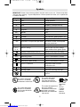
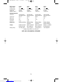
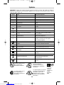
IMPORTANT: Some of the following symbols may be used on your tool. Please study them
and learn their meaning. Proper interpretation of these symbols will allow you to operate the
tool better and safer.
Symbol Name Designation/Explanation
V Volts Voltage (potential)
A Amperes Current
Hz Hertz Frequency (cycles per second)
W Watt Power
kg Kilograms Weight
min Minutes Time
s Seconds Time
Diameter Size of drill bits, grinding wheels, etc.
n0No load speed Rotational speed, at no load
.../min Revolutions or reciprocation per minute Revolutions, strokes, surface speed,
orbits etc. per minute
0 Off position Zero speed, zero torque...
1, 2, 3, ... Selector settings Speed, torque or position settings.
I, II, III, Higher number means greater speed
Infinitely variable selector with off Speed is increasing from 0 setting
Arrow Action in the direction of arrow
Alternating current Type or a characteristic of current
Direct current Type or a characteristic of current
Alternating or direct current Type or a characteristic of current
Class II construction Designates Double Insulated
Construction tools.
Earthing terminal Grounding terminal
Warning symbol Alerts user to warning messages
Ni-Cad RBRC seal Designates Ni-Cad battery recycling
program
Symbols
A
0
A
0
A
0
A
0
A
A
A
This symbol designates
that this tool is listed by
Underwriters Laboratories.
This symbol designates
that this tool is listed by
the Canadian Standards
Association.
This symbol designates
that this tool is listed to
Canadian Standards by
Underwriters Laboratories. This symbol
designates
that
this tool
complies
to NOM
Mexican
Standards.
This symbol designates that
this tool is listed by
Underwriters Laboratories,
and listed to Canadian
Standards by Underwriters
Laboratories.
BM 2609140358 12-05 12/6/05 3:28 PM Page 7
Downloaded from www.Manualslib.com manuals search engine

-8-
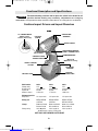
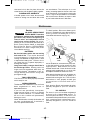
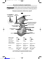
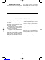
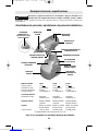
Functional Description and Specifications
Disconnect battery pack from tool or place the switch in the locked or off
position before making any assembly, adjustments or changing
accessories.Such preventive safety measures reduce the risk of starting the tool accidentally.
!
WARNING
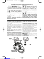
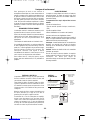
Cordless Impact Drivers and Impact Wrenches
VARIABLE SPEED
TRIGGER SWITCH
FORWARD/REVERSING
LEVER & TRIGGER LOCK
RUBBERIZED GRIP
BATTERY
RELEASE TABS
BATTERY PACK
VENTILATION
OPENINGS
BRUSH COVER
LOCKING
SLEEVE
BELT CLIP
(Optional Accessory)
SWIVEL LIGHTING
SYSTEM
BIT AND BIT
STORAGE
FIG. 1
1/2"SQUARE DRIVE
(Models 22612,
22614 & 22618 only)
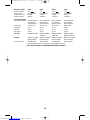
Model number 22612 22614 22618
Voltage rating 12 V 14.4 V 18 V
No load speed n00-2,800/min n00-2,800/min n00-2,800/min
Impact rate 0-3,200 0-3,200 0-3,200
Maximum torque 1,550 in-lbs 1,770 in-lbs 1,950 in-lbs
Maximum Capacities
Output drive 1/2" Square drive 1/2" Square drive 1/2" Square drive
Battery pack BAT043-BAT046 BAT038-BAT041 BAT025, BAT026,
& BAT120 & BAT140 BAT180 & BAT181
Charger BC001-6 & BC016 BC001-6 & BC016 BC003, 4, 6 & BC016
BC130 & BC230 BC130 & BC230 BC130 & BC230
Voltage rating 120 V 60 Hz 120 V 60 Hz 120 V 60 Hz
BC006 charger requires 12 V DC input
NOTE: ONLY USE CHARGERS LISTED ABOVE
BM 2609140358 12-05 12/6/05 3:28 PM Page 8
Downloaded from www.Manualslib.com manuals search engine

-9-
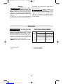
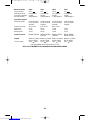
Model number 23609 23612 23614 23618
Voltage rating 9.6 V 12 V 14.4 V 18 V
No load speed n00-2,800/min n00-2,800/min n00-2,800/min n00-2,800/min
Impact rate 0-3,200 0-3,200 0-3,200 0-3,200
Maximum torque 950 in-lbs 1,050 in-lbs 1,150 in-lbs 1,350 in-lbs
Maximum Capacities
Chuck size 1/4" Hex-shank 1/4" Hex-shank 1/4" Hex-shank 1/4" Hex-shank
with power groove with power groove with power groove with power groove
Screw sizes #12 x 3" #14 x 3" #16 x 3" #16 x 3"
Mild metal 1/4" 3/8" 1/2" 3/4"
Hard wood 3/4" 1-1/4" 1-1/2" 2"
Soft wood 1-1/4" 1-1/2" 2" 3"
Battery pack BAT048 & BAT100 BAT043-BAT046 BAT038-BAT041 BAT025, BAT026,
& BAT120 & BAT140 BAT180 & BAT181
Charger BC001-6 & BC016 BC001-6 & BC016 BC001-6 & BC016 BC003, 4, 6 & BC016
BC130 & BC230 BC130 & BC230 BC130 & BC230 BC130 & BC230
Voltage rating 120 V 60 Hz 120 V 60 Hz 120 V 60 Hz 120 V 60 Hz
BC006 charger requires 12 V DC input
NOTE: ONLY USE CHARGERS LISTED ABOVE
BM 2609140358 12-05 12/6/05 3:28 PM Page 9
Downloaded from www.Manualslib.com manuals search engine

-10-
Operating Instructions
INTENDED USE
This tool is intended for the fastening and
loosening of bolts, nuts and various threaded
fasteners. This tool is not intended for use as a
drill.
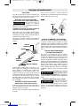
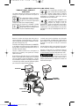
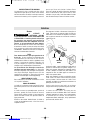
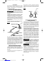
INSERTING AND REMOVING
ACCESSORIES
(Models 23609, 23612, 23614 & 23618 only)
To avoid loss of control,
ensure bit is locked in chuck
by pulling on bit after it has been inserted.
The chuck accepts only standard 1/4"
hexagonal shank accessories with power
groove.
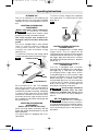
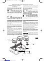
Your tool is equipped with a quick release
chuck. To insert an accessory, simply pull
locking sleeve forward, insert desired
accessory into chuck and release locking
sleeve (Fig. 2).
To remove an accessory, pull locking sleeve
forward and simply remove it from the chuck.
Do not use this tool as a drill. Tools equipped
with shut-off clutches are not designed for
drilling applications. The clutch can shut off
automatically and without warning. Attempting
to restart drilling after shut-off has been
reached can cause the tool to twist out of your
hand until the clutch again reaches shut-off.
Do not attempt to insert quick-change type drill
bits into this chuck.
INSERTING AND REMOVING
ACCESSORIES
(Models 22612, 22614 & 22618 only)
Attach only high quality accessories with the
proper size square drive designed for use with
impact wrenches.
Your impact wrench is equipped with a 1/2"
square drive.
To install a socket, simply push completely
onto output drive. To remove, pull off output
drive (Fig. 3).
VARIABLE SPEED CONTROLLED
TRIGGER SWITCH
Your tool is equipped with a variable speed
trigger switch. The tool speed can be
controlled from the minimum to the maximum
nameplate RPM by the pressure you apply to
the trigger. Apply more pressure to increase
the speed and release pressure to decrease
speed (Fig. 1).
FORWARD/REVERSING LEVER &
TRIGGER LOCK
Your tool is equipped with a forward/
reversing lever and trigger lock located above
the trigger (Fig. 1). This lever was designed
for changing rotation of the chuck, and for
locking the trigger in an “OFF” position to help
prevent accidental starts and accidental
battery discharge. For forward rotation, (with
chuck pointed away from you) move the lever
to the far left. For reverse rotation move the
lever to the far right. To activate trigger lock
move lever to the center off position.
Do not change direction of
rotation until the tool
comes to a complete stop. Shifting during
rotation of the chuck can cause damage to
the tool.
BELT CLIP (Optional Accessory)
When the tool is attached to
the belt, position yourself to
avoid entanglement with surrounding objects.
Unexpected entanglement could cause the
tool to fall resulting in injury to the operator or
bystanders.
!
WARNING
!
CAUTION
LOCKING SLEEVE
CHUCK
FIG. 2
SCREWDRIVER BIT
BIT
HOLDER
SCREWDRIVER
BIT
OUTPUT
DRIVE
SOCKET
FIG. 3
!
WARNING
BM 2609140358 12-05 12/6/05 3:28 PM Page 10
Downloaded from www.Manualslib.com manuals search engine

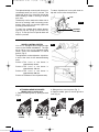
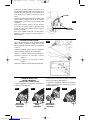
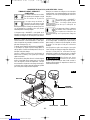
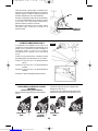
ATTACHING GEAR BOX COVER
(Models 22618 & 23618 only)
1. Remove rubber guard by pulling forward
(Fig. 6).
2. Slide gear box cover into place (Fig. 7).
3. Replace rubber guard to secure gear box
cover (Fig. 8).
-11-
The optional belt clip accessory will allow you to
conveniently attach your tool to your belt. This
feature will allow you to have both hands free
when climbing a ladder or moving to another
work area.
The belt clip can be attached to either side of
the tool by securing it with a mounting screw.
Always make sure you securely tighten the
mounting screw before use.
To open clip, squeeze both release buttons
and the clip will spring up automatically
(Fig. 4). To use clip, turn tool upside down and
attach to your belt.
To retract clip when not in use, push down on
clip until it locks in the closed position.
RUBBER
GUARD
FIG. 6
GEAR BOX
COVER
FIG. 7
RUBBER
GUARD
FIG. 8 FIG. 9
CLIP
RELEASE
BUTTONS
FIG. 4
SWIVEL LIGHTING SYSTEM
Your tool is equipped with integrated light
source in the knurled thumbwheel. The light
will go ON as soon as you squeeze trigger
switch, unless the thumbwheel is in the 0
position (Fig. 5).
The light beam can be adjusted to 3 positions
in front of the chuck for the desired bit being
used.
Position 1: The focus of the beam is
approximately 20 mm.
Position 2: The focus of the beam is
approximately 150 mm.
Position 3: The focus of the beam is
approximately 500 mm.
Position 0: The beam is shut off permanently.
FIG. 5
BM 2609140358 12-05 12/6/05 3:28 PM Page 11
Downloaded from www.Manualslib.com manuals search engine

-12-
INSERTING AND RELEASING
BATTERY PACK
Release battery pack from tool by pressing
on both sides of the battery release tabs and
pull downward. Before inserting battery pack,
remove protective cap from battery pack. To
insert battery, align battery and slide battery
pack into tool until it locks into position. Do
not force (Fig. 1).
1. The battery pack accepts only about 80%
of its maximum capacity with its first few
charge cycles. However, after the first few
charge cycles, the battery will charge to full
capacity.
2. The charger was designed to fast charge
the battery only when the battery
temperature is between 40˚F (4˚C) and
105˚F (41˚C).
3. Asubstantial drop in operating time per
charge may mean that the battery pack is
nearing the end of its life and should be
replaced.
4. If you anticipate long periods (i.e. a month
or more) of non-use of your tool, it is best to
run your tool down until it is fully discharged
before storing your battery pack. After a long
period of storage, the capacity at first recharge
will be lower. Normal capacity will be restored
in two or three charge/discharge cycles.
Remember to unplug charger during storage
period.
5. If battery does not charge properly:
a. Check for voltage at outlet by plugging
in some other electrical device.
b. Check to see if outlet is connected to a
light switch which turns power “off” when
lights are turned off.
c. Check battery pack terminals for dirt.
Clean with cotton swab and alcohol if
necessary.
d. If you still do not get proper charging,
take or send tool, battery pack and charger
to your local Bosch Service Center. See
“Tools, Electric” in the Yellow Pages for
names and addresses.
Note: Use of chargers or battery packs not
sold by Bosch will void the warranty.
IMPORTANT CHARGING NOTES
BM 2609140358 12-05 12/6/05 3:28 PM Page 12
Downloaded from www.Manualslib.com manuals search engine

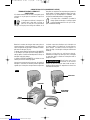
-13-
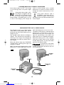
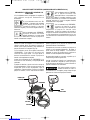
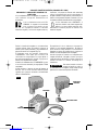
Plug charger cord into your standard power
outlet. Before inserting battery pack, remove
protective cap, then insert battery pack into
charger (Fig. 10).
The charger’s green indicator light will begin to
“BLINK”. This indicates that the battery is
receiving a fast charge. Fast-charging will
automatically stop when the battery pack is
fully charged.
When the indicator light stops “BLINKING”
(and becomes a steady green light) fast
charging is complete.
The battery pack may be used even though
the light may still be blinking. The light may
require more time to stop blinking depending
on temperature. When you begin the charging
process of the battery pack, a steady red light
could also mean the battery pack is too hot or
too cold.
The purpose of the green light is to indicate
that the battery pack is fast-charging. It does
not indicate the exact point of full charge. The
light will stop blinking in less time if the battery
pack was not completely discharged.
When charging several batteries in sequence,
the charge time may slightly increase.
When the battery pack is fully charged,
unplug the charger (unless you're charging
another battery pack) and slip the battery
pack back into the tool.
To prevent fire or injury when
batteries are not in tool or
charger, always place protective cap onto
end of battery pack.
CHARGER INDICATORS, SYMBOLS
AND MEANING
If the indicator lights are “OFF”, the charger
is not receiving power from power supply
outlet.
If the green indicator light is
“ON”, the charger is plugged in
but the battery pack is not
inserted, or the battery pack is fully charged
and is being trickle charged.
If the green indicator light is
“BLINKING”, the battery pack is
being fast-charged. Fast-
charging will automatically stop when the
battery pack is fully charged.
If the red indicator light is “ON”,
the battery pack is too hot or
cold for fast-charging. The
charger will switch to trickle charge, until a
suitable temperature is reached, at which
time the charger will switch automatically to
fast-charging.
If the red indicator light is
“BLINKING”, the battery pack
cannot accept a charge or the
contacts of the charger or battery pack are
contaminated. Clean the contacts of the
charger or battery pack only as directed in
these operating instructions or those supplied
with your tool or battery pack.
CHARGING BATTERY PACK (30 MINUTE SINGLE BAY-BC130)
CHARGER
BATTERY
PACK
PROTECTIVE
CAP
GREEN LIGHT
RED LIGHT
FIG. 10
!
WARNING
BM 2609140358 12-05 12/6/05 3:28 PM Page 13
Downloaded from www.Manualslib.com manuals search engine

-14-
CHARGING BATTERY PACK (30 MINUTE DUAL BAY-BC230)
CHARGER INDICATORS, SYMBOLS
AND MEANING
If the indicator lights are “OFF”, the charger is
not receiving power from power supply outlet.
If the red indicator light is “ON”,
the battery pack is too hot or
cold for fast-charging. The
charger will switch to trickle charge, until a
suitable temperature is reached, at which time
the charger will switch automatically to fast-
charging.
If the red indicator light is
“BLINKING”, the battery pack
cannot accept a charge or the
contacts of the charger or battery pack are
contaminated. Clean the contacts of the
charger or battery pack only as directed in
these operating instructions or those supplied
with your tool or battery pack.
If the green indicator light is
“BLINKING”, the battery pack
is being fast-charged. Fast-
charging will automatically stop when the
battery pack is fully charged.
If the green indicator light is
“ON”, the charger is plugged in
but the battery pack is not
inserted, or the battery pack is fully charged
and is being trickle charged.
Plug charger cord into your standard power
outlet. Before inserting battery pack, remove
protective cap, then insert battery pack into
charger (Fig. 11).
The charger’s green indicator light will begin to
“BLINK”. This indicates that the battery is
receiving a fast charge. Fast-charging will
automatically stop when the battery pack is
fully charged.
When the indicator light stops “BLINKING”
(and becomes a steady green light) fast
charging is complete.
The battery pack may be used even though
the light may still be blinking. The light may
require more time to stop blinking depending
on temperature. When you begin the charging
process of the battery pack, a steady red light
could also mean the battery pack is too hot or
too cold.
The purpose of the green light is to indicate
that the battery pack is fast-charging. It does
not indicate the exact point of full charge. The
light will stop blinking in less time if the battery
pack was not completely discharged.
When charging several batteries in sequence,
the charge time may slightly increase.
When the battery pack is fully charged, unplug
the charger (unless you're charging another
battery pack) and slip the battery pack back
into the tool.
To prevent fire or injury when
batteries are not in tool or
charger, always place protective cap onto end
of battery pack.
CHARGER
BATTERY
PACK
PROTECTIVE
CAP
FIG.11
GREEN LIGHT
RED LIGHT
!
WARNING
BM 2609140358 12-05 12/6/05 3:28 PM Page 14
Downloaded from www.Manualslib.com manuals search engine

-15-
Plug charger cord into your standard power
outlet. Before inserting battery pack, remove
protective cap, then insert battery pack into
charger (Fig. 12).
The charger’s green indicator will begin to
“BLINK”. This indicates that the battery is
receiving a fast charge. Fast-charging will
automatically stop when the battery pack is
fully charged.
When the indicator light stops “BLINKING”
(and becomes a steady green light) fast
charging is complete.
When you begin the charging process of the
battery pack, a steady green light could also
mean the battery pack is too hot or too cold.
The purpose of the light is to indicate that the
battery pack is fast-charging. It does not
indicate the exact point of full charge. The
light will stop blinking in less time if the
battery pack was not completely discharged.
When the battery pack is fully charged,
unplug the charger (unless you're charging
another battery pack) and slip the battery
pack back into the tool handle.
To prevent fire or injury when
batteries are not in tool or
charger, always place protective cap onto
end of battery pack.
CHARGING BATTERY PACK (1 HOUR CHARGER)
CHARGER INDICATORS, SYMBOLS AND MEANING
If the indicator lights are “OFF”, the charger
is not receiving power from power supply
outlet.
If the green indicator light is “ON”,
the charger is plugged in but the
battery pack is not inserted, or the
battery pack is fully charged and is being
trickle charged, or the battery pack is too hot
or cold for fast-charging. The charger will
switch to trickle charge, until a suitable
temperature is reached, at which time the
charger will switch automatically to fast-
charging.
If the green indicator light is
“BLINKING”, the battery pack is
being fast-charged. Fast-charging
will automatically stop when the battery pack
is fully charged.
INDICATOR
LIGHT
CHARGER
BATTERY
PACK
PROTECTIVE
CAP
FIG. 12
!
WARNING
BM 2609140358 12-05 12/6/05 3:28 PM Page 15
Downloaded from www.Manualslib.com manuals search engine

You will extend the life of your bits and do
neater work if you always put the bit in
contact with the work before pulling the
trigger. During the operation, hold the tool
firmly and exert light, steady pressure. Too
much pressure at low speed will stall the tool.
Too little pressure will keep the bit from
cutting and cause excess friction by sliding
over the surface. This can be damaging to
both tool and bit.
DRIVING WITH VARIABLE SPEED
The technique is to start slowly, increasing
the speed as the screw runs down. Set the
screw snugly by slowing to a stop. Prior to
driving screws, pilot and clearance holes
should be drilled.
Always hold the machine straight on the bolt
to be tightened.
The best method to determine the right
impacting/tightening duration is by means of
atrial. For small screws, the right
impacting/tightening duration can be reached
in less then 0.5 Sec. Therefore, work with low
RPM and switch the machine off immediately
when the screw is tight and the impacting
sound can be heard.
For screwing larger, longer wood screws into
hard material, pre-drilling is the best method.
TIGHTENING TORQUE
The tightening torque depends on the
duration of the impacting/tightening action.
The largest tightening torque is achieved
after approx. 6 to 10 Sec. impacting/
tightening action.
The torque build-up depends on the
following factors:
• Hardness of the bolts/nuts.
• Type of washer (disk washer, spring
washer, seal).
• Hardness of the material to be joined.
• Lubricating effect at the surfaces of the
junction.
This leads to the following application cases:
Hard case: The joining of metal to metal with
adisk washer. The maximum torque is
reached after a relative short impacting/
tightening action.
Medium case: The joining of metal to metal
where spring ring washer, disk spring
washer, stud bolts or bolts/nuts with conical
seats are used.
Soft case: The joining of e.g. metal to wood
or insulation material.
For middle or soft joining cases, the
maximum tightening torque is less as for
hard cases. Therefore, a longer impacting/
tightening action is necessary to arrive at the
maximum tightening torque.
Operating Tips
-16-
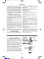
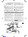
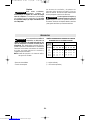
FASTENING WITH SCREWS
This procedure shown in (Fig. 13) will enable
you to fasten materials together with your tool
without stripping, splitting or separating the
material.
First, clamp the pieces together and drill the
first hole 2/3 the diameter of the screw. If the
material is soft, drill only 2/3 the proper
length. If it is hard, drill the entire length.
Second, unclamp the pieces and drill the
second hole the same diameter as the screw
shank in the first or top piece of wood.
Third, if flat head screw is used, countersink
the hole to make the screw flush with the
surface. Then, simply apply even pressure
when driving the screw. The screw shank
2. Drill same
diameter as
screw shank.
3. Countersink
same diameter
as screw head.
1. Drill 2/3 diameter and
2/3 of screw length for
soft materials, full
length for hard
materials.
Screw
Apply a slight
even pressure
when driving
screws.
FASTENING
WITH SCREWS
FIG. 13
BM 2609140358 12-05 12/6/05 3:28 PM Page 16
Downloaded from www.Manualslib.com manuals search engine

Service
NO USER SERVICEABLE
PARTS INSIDE. Preventive
maintenance performed by unauthorized
personnel may result in misplacing of
internal wires and components which
could cause serious hazard. We recom-
mend that all tool service be performed by a
Bosch Factory Service Center or Authorized
Bosch Service Station. SERVICEMEN:
Disconnect tool and/or charger from power
source before servicing.
BATTERIES
Be alert for battery packs that are nearing
their end of life. If you notice decreased
tool performance or significantly shorter
running time between charges then it is time
to replace the battery pack. Failure to do so
can cause the tool to operate improperly or
damage the charger.
Long term battery storage should be in
the discharged state. Battery packs last
longer and re-charge better when they are
stored discharged. Remember to fully re-
charge battery packs before using after
prolonged storage.
TOOL LUBRICATION
Your Bosch tool has been properly lubricated
and is ready for use.
CARBON BRUSHES
The brushes and commutator in your tool have
been engineered for many hours of
dependable service.
If your tool runs sporadically, loses power,
makes unusual noises or runs at a reduced
speed, check the brushes. To continue using
the tool in this condition will permanently
damage your tool.
Check both brushes. Usually the brushes will
not wear out simultaneously. If one brush is
worn out, replace both brushes.
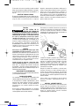
To check brushes: Disconnect battery pack
from tool. Rotate brush cap at the rear part of
housing counter-clockwise with a coin or
screwdriver and remove cap (Fig. 14).
Lift out the brushes; note which way they face,
so that the brushes can be returned to their
original position. New brushes can also be
inserted turned 180º. Clean the brush holder
openings with compressed air or a clean cloth
and replace the brushes and brush covers.
After replacing brushes the tool should be run
at no-load and run it freely at full speed for 2
minutes before using the tool. This will allow
the brushes to “seat” properly and will give
you more hours of life from each set of
brushes.
Only genuine Bosch replacement brushes
specially designed for your tool should be
used.
D.C. MOTORS
The motor in your tool has been engineered
for many hours of dependable service. To
maintain peak efficiency of the motor, we
recommend it be examined every six months.
Only a genuine Bosch replacement motor
specially designed for your tool should be
used.
Maintenance
!
WARNING
BRUSH
CAP
BRUSH
FIG. 14
-17-
clearance hole in the first piece allows the
screw head to pull the pieces tightly together.
RUNNING NUTS AND BOLTS
Variable speed control must be used with
caution for driving nuts and bolts with socket
set attachments. The technique is to start
slowly, increasing speed as the nut or bolt runs
down. Set the nut or bolt snugly by slowing the
tool to a stop. If this procedure is not followed,
the tool will have a tendency to torque or twist
in your hands when the nut or bolt seats.
BM 2609140358 12-05 12/6/05 3:28 PM Page 17
Downloaded from www.Manualslib.com manuals search engine

Cleaning
To avoid accidents, always
disconnect the tool and/or
charger from the power supply before
cleaning. The tool may be cleaned most
effectively with compressed dry air. Always
wear safety goggles when cleaning tools
with compressed air.
Ventilation openings and switch levers must
be kept clean and free of foreign matter. Do
not attempt to clean by inserting pointed
objects through opening.
Certain cleaning agents
and solvents damage
plastic parts. Some of these are: gasoline,
carbon tetrachloride, chlorinated cleaning
solvents, ammonia and household detergents
that contain ammonia.
-18-
*Screwdriver bit
*Carrying case
(* = standard equipment)
(** = optional accessories)
Accessories
If an extension cord is
necessary, a cord with
adequate size conductors that is capable
of carrying the current necessary for your
tool must be used. This will prevent
excessive voltage drop, loss of power or
overheating. Grounded tools must use 3-
wire extension cords that have 3-prong plugs
and receptacles.
NOTE: The smaller the gauge number, the
heavier the cord.
RECOMMENDED SIZES OF EXTENSION CORDS
120 VOLT ALTERNATING CURRENT TOOLS
!
WARNING
!
WARNING
!
CAUTION
Tool’s
Ampere
Rating
Cord Size in A.W.G. Wire Sizes in mm2
3-6
6-8
8-10
10-12
12-16
18 16 16 14 0.75 0.75 1.5 2.5
18 16 14 12 0.75 1.0 2.5 4.0
18 16 14 12 0.75 1.0 2.5 4.0
16 16 14 12 1.0 2.5 4.0 —
14 12 — — — — — —
25 50 100 150 15 30 60 120
Cord Length in Feet Cord Length in Meters
BM 2609140358 12-05 12/6/05 3:28 PM Page 18
Downloaded from www.Manualslib.com manuals search engine

-19-
Sécurité du lieu de travail
Maintenez le lieu de travail propre et bien éclairé.
Les risques d’accident sont plus élevés quand on
travaille dans un endroit encombré ou sombre.
N’utilisez pas d’outils électroportatifs dans des
atmosphères explosives, comme par exemple en
présence de gaz, de poussières ou de liquides
inflammables. Les outils électroportatifs produisent
des étincelles qui risquent d’enflammer les poussières
ou les vapeurs.
Éloignez les enfants et les visiteurs quand vous vous
servez d’un outil électroportatif. Vous risquez une
perte de contrôle si on vous distrait.
Sécurité électrique
Les fiches des outils électroportatifs doivent
correspondre à la prise. Il ne faut absolument jamais
modifier la fiche. N’utilisez pas d’adaptateur de prise
avec des outils électroportatifs munis d’une fiche de
terre. Le risque de choc électrique est moindre si on
utilise une fiche non modifiée sur une prise qui lui
correspond.
Évitez tout contact du corps avec des surfaces reliées
àla terre tels que tuyaux, radiateurs, gazinières ou
réfrigérateurs. Le risque de choc électrique augmente
si votre corps est relié à la terre.
N’exposez pas les outils électroportatifs à la pluie ou
àl’humidité. Si de l’eau pénètre dans un outil
électroportatif, le risque de choc électrique augmente.
Ne maltraitez pas le cordon. Ne vous en servez
jamais pour transporter l’outil électroportatif, pour le
tirer ou pour le débrancher. Éloignez le cordon de la
chaleur, des huiles, des arêtes coupantes ou des
pièces mobiles. Les cordons abîmés ou emmêlés
augmentent les risques de choc électrique.
Si vous utilisez un outil électroportatif à l’extérieur,
employez une rallonge conçue pour l’extérieur. Ces
rallonges sont faites pour l’extérieur et réduisent le
risque de choc électrique.
N’utilisez pas un outil conçu uniquement pour le C.A.
sur une alimentation en C.C. Même si l’outil semble
fonctionner, les composants électriques d’un outil prévu
pour le C.A. tomberont probablement en panne et
risquent de créer un danger pour l’utilisateur.
S’il est nécessaire d’utiliser l’outil dans un lieu
humide, il faut l’alimenter par l’intermédiaire d’un
disjoncteur différentiel de fuite à la terre (DDFT).
L’emploi d’un DDFT et de dispositifs de protection
personnelle tels que gants et chaussures d’électricien en
caoutchouc améliorent votre sécurité personnelle.
Sécurité personnelle
Restez concentré, faites attention à ce que vous
faites, et servez-vous de votre bon sens lorsque vous
utilisez un outil électroportatif. N'employez pas
d’outils électroportatifs quand vous êtes fatigué ou
sous l’emprise de drogues, d’alcool ou de
médicaments. Quand on utilise des outils
électroportatifs, il suffit d’un moment d’inattention pour
causer des blessures corporelles graves.
Utilisez des équipements de sécurité. Portez toujours
une protection oculaire. Si les conditions le
demandent, il faut porter un masque à poussière, des
chaussures de sécurité antidérapantes, un casque de
chantier ou une protection auditive pour réduire le
risque de blessure corporelle.
Évitez les démarrages intempestifs. Assurez-vous
que l’interrupteur est en position arrêt (OFF) avant de
brancher l’outil. Transporter un outil électroportatif
avec le doigt sur la gâchette ou le brancher quand
l’interrupteur est en position “marche” (ON) présente
des risques d’accident.
Enlevez toutes les clés de réglage avant de mettre
l’outil électroportatif en marche. Si on laisse une clé
sur une pièce tournante de l’outil électroportatif, il y a
risque de blessure corporelle.
Ne vous penchez pas. Conservez toujours une bonne
assise et un bon équilibre. Ceci vous permettra de
mieux maîtriser l’outil électroportatif dans des situations
inattendues.
Habillez-vous de manière appropriée. Ne portez pas
de vêtements amples ou de bijoux. Attachez les
cheveux longs. N’approchez pas les cheveux, les
vêtements ou les gants des pièces en mouvement.
Les vêtements amples, les bijoux ou les cheveux longs
risquent d’être happés par les pièces en mouvement.
Si l’outil est muni de dispositifs permettant le
raccordement d’un système d’aspiration et de
collecte des poussières, assurez-vous que ces
dispositifs sont raccordés et utilisés correctement.
L’utilisation de ces dispositifs peut permettre de réduire
les dangers liés à la poussière.
Veuillez lire et comprendre toutes les consignes. Si on n'observe pas toutes les
consignes décrites ci-dessous, il y a risque de choc électrique, d’incendie et/ou de
blessures corporelles graves. Dans toutes les mises en garde ci-dessous, le terme « outil électroportatif » se
rapporte à des outils branchés sur le secteur (avec fil) ou à des outils alimentés par piles (sans fil).
CONSERVEZ CES CONSIGNES
Consignes générales de sécurité
AVERTISSEMENT
!
BM 2609140358 12-05 12/6/05 3:28 PM Page 19
Downloaded from www.Manualslib.com manuals search engine

-20-
Maintenez les poignées sèches et exemptes d’huile et
degraisse. Onne pas maîtriser un outil électroportatif
entoute sécurité quand on a les mains glissantes.
Utilisation et entretien des outils
électroportatifs
Ne forcez pas sur l’outil électroportatif. Utilisez l’outil
électroportatif qui convient à la tâche à effectuer.
L’outil qui convient à la tâche fait un meilleur travail et
est plus sûr à la vitesse pour lequel il a été conçu.
Ne vous servez pas de l’outil électroportatif si son
interrupteur ne parvient pas à le mettre en marche ou
àl’arrêter. Tout outil électroportatif qui ne peut pas
être commandé par son interrupteur est dangereux et
doit être réparé.
Débranchez la fiche de la prise ou enlevez le bloc-
piles de l’outil électroportatif avant tout réglage,
changement d’accessoires ou avant de ranger l’outil
électroportatif. De telles mesures de sécurité
préventive réduisent le risque de démarrage intempestif
de l’outil électroportatif.
Rangez les outils électroportatifs dont vous ne vous
servez pas hors de portée des enfants et ne permettez
pas à des personnes qui ne connaissent pas l’outil
électroportatif ou qui ignorent ces consignes de s’en
servir. Les outils électroportatifs sont dangereux dans
les mains d’utilisateurs inexpérimentés.
Entretenez les outils électroportatifs. Vérifiez que les
pièces mobiles sont alignées correctement et ne
coincent pas. Vérifiez qu’il n’y a pas de pièces
cassées ou d’autre circonstance qui risquent
d’affecter le fonctionnement de l’outil électroportatif.
Si l’outil est abîmé, faites-le réparer avant de
l’utiliser. De nombreux accidents sont causés par des
outils électroportatifs mal entretenus.
Maintenez les outils coupants affûtés et propres. Les
outils coupants entretenus correctement et dotés de
bords tranchants affûtés sont moins susceptibles de
coincer et sont plus faciles à maîtriser.
Utilisez l’outil électroportatif, les accessoires, les
embouts etc. selon ces consignes et de la manière
prévue pour chaque type particulier d’outil
électroportatif en tenant compte des conditions de
travail et de la tâche à accomplir. L'emploi d’outils
électroportatifs pour des tâches différentes de celles
pour lesquelles ils ont été prévus peut résulter en une
situation dangereuse.
Utilisez des brides ou d’autres moyens pratiques de
brider ou de supporter la pièce sur une plate-forme
stable. Tenir la pièce à la main ou contre le corps est
instable et risque de résulter en une perte de contrôle.
Utilisation et entretien des outils à piles
Veillez à ce que l’interrupteur soit dans la position de
fermeture avant d’insérer le bloc-piles. L’insertion
d’un bloc-piles dans un outil électroportatif dont
l’interrupteur est dans la position de marche est une
invite aux accidents.
Rechargez les piles uniquement avec le chargeur
spécifié par le fabriquant. Un chargeur qui convient à
un type de bloc-piles peut entraîner un risque d’incendie
quand il est utilisé avec un autre bloc-piles.
Utilisez des outils alimentés par piles uniquement
avec les blocs-piles spécifiquement désignés pour
eux. L’utilisation de tout autre bloc-piles peut créer un
risque de blessures et d’incendie.
Lorsque le bloc-piles n’est pas utilisé, gardez-le à
distances d’autres objets métalliques tels que des
trombones, des pièces de monnaie, des clés, des
clous, des vis ou de tout autre objet métallique
pouvant faire une connexion entre une borne et une
autre. Court-circuiter les bornes des piles peut causer
des brûlures ou un incendie.
Dans des conditions abusives, du liquide peut être
éjecté de la pile ; dans un tel cas, évitez tout contact
avec ce liquide. Si un contact se produit
accidentellement, rincez avec de l’eau. Si le liquide
entre en contact avec les yeux, consultez un médecin.
Du liquide éjecté de la pile peut causer des irritations ou
des brûlures.
Entretien
Faites réparer votre outil électroportatif par un agent
de service qualifié n’utilisant que des pièces de
rechange identiques. Ceci assure que la sécurité de
l’outil électroportatif est préservée.
Créez un agenda d’entretien périodique pour votre
outil. Quand vous nettoyez un outil, faites attention
de n’en démonter aucune pièce car il est toujours
possible de mal remonter ou de pincer les fils
internes ou de remonter incorrectement les ressorts
de rappel des capots de protection. Certains agents
de nettoyage tels que l’essence, le tétrachlorure de
carbone, l’ammoniaque, etc. risquent d’abîmer les
plastiques.
CONSERVEZ CES INSTRUCTIONS
BM 2609140358 12-05 12/6/05 3:28 PM Page 20
Downloaded from www.Manualslib.com manuals search engine
La page charge ...
La page charge ...
La page charge ...
La page charge ...
La page charge ...
La page charge ...
La page charge ...
La page charge ...
La page charge ...
La page charge ...
La page charge ...
La page charge ...
La page charge ...
La page charge ...
La page charge ...
La page charge ...
La page charge ...
La page charge ...
La page charge ...
La page charge ...
La page charge ...
La page charge ...
La page charge ...
La page charge ...
La page charge ...
La page charge ...
La page charge ...
La page charge ...
La page charge ...
La page charge ...
La page charge ...
La page charge ...
La page charge ...
La page charge ...
La page charge ...
La page charge ...
-
 1
1
-
 2
2
-
 3
3
-
 4
4
-
 5
5
-
 6
6
-
 7
7
-
 8
8
-
 9
9
-
 10
10
-
 11
11
-
 12
12
-
 13
13
-
 14
14
-
 15
15
-
 16
16
-
 17
17
-
 18
18
-
 19
19
-
 20
20
-
 21
21
-
 22
22
-
 23
23
-
 24
24
-
 25
25
-
 26
26
-
 27
27
-
 28
28
-
 29
29
-
 30
30
-
 31
31
-
 32
32
-
 33
33
-
 34
34
-
 35
35
-
 36
36
-
 37
37
-
 38
38
-
 39
39
-
 40
40
-
 41
41
-
 42
42
-
 43
43
-
 44
44
-
 45
45
-
 46
46
-
 47
47
-
 48
48
-
 49
49
-
 50
50
-
 51
51
-
 52
52
-
 53
53
-
 54
54
-
 55
55
-
 56
56


Bosch GDR 12V 2 Manuel utilisateur
- Catégorie
- Perceuses mixtes sans fil
- Taper
- Manuel utilisateur
dans d''autres langues
- English: Bosch GDR 12V 2 User manual
- español: Bosch GDR 12V 2 Manual de usuario
Documents connexes
-
Bosch Power Tools 22612 Manuel utilisateur
-
-
-
-
Bosch 33618-2G Le manuel du propriétaire
-
-
-