La page est en cours de chargement...

LVRS8-DIN • Les Numéros de Catalogue • Los Números de Catálogo:
Country of Origin: Made in China • Pays d’origine: Fabriqué en Chine • País de origen: Hecho en China
OVERVIEW
SOFTWARE / FIRMWARE
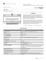
Vantage’s DIN Low Voltage Relay Station features eight isolated, latching relay
channels for switching low-voltage or dry contact closures to third party systems
or devices. The DIN LVRS does not produce or provide any power. Each relay
is single-pole, doublethrow, which offers a normally closed, normally open set
of contacts for each relay. Each relay has an actuator button on the front of
the LVRS which toggles the relay and is useful for testing wiring and operation
without programming the system. Some examples for using a DIN LVRS would
be: draperies, pumps, garage doors, HVAC dampers, lifts, screens, pool covers,
sprinklers, showers, baths, security systems, etc.
The WireLink model is compatible with InFusion Design Center software or QLink 3.5 and Controller Firmware 6.5 or higher. For new
projects it is recommended that rmware and software be kept to the most current release.
36V stations have a symbol on the Serial Number sticker. Any station, not displaying this symbol, should not be
connected to a 36Volt Station Bus.
Description Specication
Dimensions, HWD 3.38” x 6.19” x 2.44” (85.7mm x 157.2mm x 61.9mm)
Weight, 1-gang 7.09 oz (201 g)
Mounting 35 mm DIN Rail (EN 50 022: 1977)
Relay Inputs 8
Relay Actuators 8
Max. Current @ Relay 1A
Max. Voltage @ Relay 48VAC / 30VDC
Min. Voltage @ Relay 0VAC / 0VDC
Lightning Surge Protection Low-voltage ITU-T K.20
Station Wiring Conguration Daisy-chain / Star / Branch
Station Bus Specication 2C, 16AWG / 1.31mm2, twisted, nonshielded, <30pF per foot
Separate a minimum of 12” / 30.5cm from other parallel communication and/or
high-voltage runs
Station Equivalent InFusion 0.5W on IC-24 / 0.5W on IC-36
Station Equivalent QLink 1 Station
Station Bus Connections* 124V / 36V Station Bus
LED Indicators Status and Load State
Ambient Operating Temperature 32-95°F (0-35°C)
Ambient Operating Humidity 5-95% non-condensing
Certications UKCA, CE, FCC, UL, cUL, EN 55032, EN 55035, EN 61000-3-2, EN 61000-3-3
SPECIFICATIONS
DIN Low-Voltage Relay Station
Installation Instructions • Instructions d’Installation • Instrucciones de Instalación
No: IS-0585 – rev. 3 11/23
4 5 6 7 832
SET
COM
RESET
SET
COM
RESET
SET
COM
RESET
SET
COM
RESET
SET
COM
RESET
SET
COM
RESET
SET
COM
RESET
SET
COM
RESET
1
MAX RATINGS
1AMP
48VAC
30VDC
1 7 82 3 4 5 6
STATUS
LOW VOLTAGE RELAY STATION 8 - DIN
SET
STATION
BUS
CLASS 2
LVRS8-DIN
OPEN ENERGY MA NA GEMENT EQUIPMENT
51XT
SERIAL NUMBER

2
No: IS-0585 – Rev. 3
INSTALLATION / MOUNTING
STATION SET UP IN SOFTWARE
Installation of Vantage products should be performed or supervised by a Certied Vantage Installer. The Low Voltage Relay
Station installation is very simple. There are two methods of connecting the Station Bus to the Low Voltage Relay Station for the
WireLink model:
1. Using the 2 wire pigtail connection located on the top of the DIN LVRS
2. Using the pins on the side of the Station to pass Station Bus (see Drawing) Part #VDC-0197
• The DIN LVRS is mounted on a standard 35 mm DIN Rail (EN 50 022: 1977).
• All low voltage connections to the LVRS relays are wired to removable screw terminal connectors. These relays may be given
custom names in software to facilitate their use in the installation.
CONNECTING DEVICE REQUIREMENTS
Each individual low voltage contact is rated as follows:
• Maximum Current = 1A
• Maximum Voltage = 48VAC/ 30VDC
INFUSION
First select the room, then click on Vantage Objects in the Object Explorer and expand Stations, WireLink. From the list of stations
double-click on the DIN LVRS to place it in the room. In the Object Editor, name the station and make sure it is on the correct Station
Bus port.
QLINK
First change to Wiring view, right click on the Main Controller and from the pop-up menu, select Add DIN Station | Low Voltage Relay
from the station list. This will reveal the DIN Relay Station Denition Dialog Box. Type the name of the Station. Click OK to exit the
Denition window. Right click on the station and select Add Low Voltage Relay to add the relay loads. In the Relay Denition window,
name the relay and assign it to the correct oor and room.
PROGRAMMING the RELAY STATION
Because there are relays, the eight buttons on the DIN LVRS cannot be programmed directly. Programmed Buttons, Time Controls or
Host Commands in InFusion and V-Commands in QLink are used to control the relays. The relays are accessed by selecting the
relay load in Programming.
CONFIGURATION WITH WIRED MODELS
When the station is rst connected to the Station Bus, the diagnostic LED will blink twice followed by a pause, meaning that the
station is connected correctly but not yet congured. From Design Center, click on the Congure Stations button on the toolbar or
from QLink, select System | Congure Stations and click on the radio Congure button in the Online Conguration section from the
pull down menu. Highlight the DIN LVRS. The Status LED will blink ve times followed by a pause and the button LEDs will blink
rapidly indicating that the station is in conguration mode. To nish conguring press any button on the Station three times. The
station may also be congured by typing the serial number in the project le, using this method the station will automatically be
congured when the system is programmed. Once congured, the Status LED will blink evenly and the buttons stop blinking.
LOCAL CONTROL
Local control of each relay is provided by pressing the corresponding actuator button on the front of the station. This allows testing of
the DIN LVRS connections before it is programmed. Each relay has an LED to indicate if it is in the SET or RESET position.
DIAGNOSTIC AND TEST INFORMATION
Each DIN LVRS station has a status LED. The Status LED blinks steady on and off or 2, 3 or 4 blinks followed by a pause.
One Even Blink: LVRS is operating correctly and is congured.
Two Blinks: LVRS is operating correctly but is not congured (wired model).
Three Blinks: LVRS is not communicating with the Main Controller, verify station bus wiring.
Four Blinks: Factory problem. Please contact the factory.
Five Blinks: Conguration mode.

MULTI-VIEW LINE DRAWING
4 5 6 7 832
SET
COM
RESET
SET
COM
RESET
SET
COM
RESET
SET
COM
RESET
SET
COM
RESET
SET
COM
RESET
SET
COM
RESET
SET
COM
RESET
1
MAX RATINGS
1AMP
48VAC
30VDC
3.38”
Strip back insulation 0.25” (6.5mm)
LOADS: Stranded, 0.75-3.31mm2 / 20-14 AWG, Copper Wire
STAT ION BUS: Vantage Station Bus
(see specifications table)
6.19”
1 7 82 3 4 5 6
STATUS
LOW VOLTAGE RELAY STATION 8 - DIN
SET
STATION
BUS
CLASS 2
LVRS8-DIN
OPEN ENERGY MANAGEMENT EQUIPMENT
51XT
SERIAL NUMBER
2.44”
Wire Gauge Max.
Screw Torque Max.
Enclosure
Ambient Temperature Max.
Load Types
For Use With Copper Wire Only
12 AWG
4.4 in/lb.
Type 1 | IP20
95°F | 35°C
Pilot Duty
LVRS8-DIN
Wire Gauge Max.
Screw Torque Max.
Enclosure
Ambient Temperature Max.
Load Types
For Use With Copper Wire Only
12 AWG
4.4 in/lb.
Type 1 | IP20
95°F | 35°C
Pilot Duty
LVRS8-DIN
Vantage warranties its products to be free of
defects in materials and workmanship for a period
of five (5) years. There are no obligations or
liabilities on the part of Vantage for consequential
damages arising out of, or in connection with,
the use or performance of this product or other
indirect damages with respect to loss of property,
revenue or profit, or cost of removal, installation
or reinstallation.
Vantage garantit que ses produits sont exempts
de défauts de matériaux et de fabrication pour
une période de cinq (5) ans. Vantage ne peut être
tenu responsable de tout dommage consécutif
causé par ou lié à l’utilisation ou à la performance
de ce produit ou tout autre dommage indirect lié
à la perte de propriété, de revenus, ou de profits,
ou aux coûts d’enlèvement, d’installation ou de
réinstallation.
Vantage garantiza que sus productos están libres
de defectos en materiales y mano de obra por un
período de cinco (5) años. No existen obligaciones
ni responsabilidades por parte de Vantage por
daños consecuentes que se deriven o estén
relacionados con el uso o el rendimiento de este
producto u otros daños indirectos con respecto a
la pérdida de propiedad, renta o ganancias, o al
costo de extracción, instalación o reinstalación.
WARRANTY INFORMATION INFORMATIONS RELATIVES À LA GARANTIE INFORMACIÓN DE LA GARANTÍA
800.555.9891
www.legrand.us/vantage
FRONT VIEW
SIDE LABEL ENLARGED
SIDE VIEW
RECOMMENDED WIRE TYPE
FOR LVRS8-DIN SCREW TERMINALS
TOP VIEW
No. IS-0585 – rev. 3 11/23
© Copyright 2023 Legrand All Rights Reserved.
© Copyright 2023 Tous droits réservés Legrand.
© Copyright 2023 Legrand Todos los derechos reservados.
/