Honeywell DR90/DR120 90 Pint Whole House Dehumidifier Guide d'installation
- Taper
- Guide d'installation

D
C
A1
A2
B
F
G1
G2
G3
G4
G5
E
TrueDRY™ DR90 (1) or
TrueDRY™ DR120 (1)
10-in. duct collar (2)
6-in. duct collar (1)
MERV 11 Filter (1)
Filter Door (2)
Installation Guide
Prestige IAQ Kit
TruelAQ
H8908 Manual Dehumidistat
VisionPRO or Prestige Thermostat
H6062 HumidiPRO Digital Humidity Control
Tools required to install TrueDRY DR90/DR120
3/8-in. hex drive
Drill or duct cutting tool
Wire stripper/cutter
Scissors or utility knife
Standard screwdriver
T25 Torx screwdriver
Duct tape
10-in. round duct and starter collar
3/4-in. male NPT to drain line adaptor (1/2-in. Dia.
recommended)
1/2-in. diameter drain line (8 ft.)
1/2-in. drain clamps (2)
Options
1/2-in. drain p-trap (may be required by local code)
Drain pan
Float switch or water sensor
PROFESSIONAL INSTALLATION GUIDE
GUIDE D’INSTALLATION PROFESSIONNELLE
GUÍA DE INSTALACIÓN PROFESIONAL
OPTIONAL CONTROLS SOLD SEPARATELY
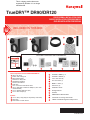
TrueDRY™ DR90/DR120
INCLUDED IN THIS BOX
G
F
E
A1A2
B C
D
69-2690EFS-06
G4G3G2G1
D
C
A
1
A
2
B
F
G
1
G
2
G
3
G
4
E
TrueDRY™ DR90 (1) or
TrueDRY™ DR120 (1)
10-in. duct collar (2)
6-in. duct collar (1)
MERV 11 Filter (1)
Filter Door (2)
Installation Guide
Prestige Comfort System (RedLINK™ Wireless)
TruelAQ
H8908 Manual Dehumidistat
VisionPRO IAQ control
Tools required to install TrueDRY DR90/DR120
3/8-in. hex drive
Drill or duct cutting tool
Wire stripper/cutter
Scissors or utility knife
Standard screwdriver
T25 Torx screwdriver
Duct tape
10-in. round duct and starter collar
3/4-in. male NPT to drain line adaptor (1/2-in. Dia.
recommended)
1/2-in. diameter drain line (8 ft.)
1/2-in. drain clamps (2)
Options
1/2-in. drain p-trap (may be required by local code)
Drain pan
Float switch or water sensor
PROFESSIONAL INSTALLATION GUIDE
GUIDE D’INSTALLATIONPROFESSIONNELLE
GUÍA DE INSTALACIÓN PROFESIONAL
OPTIONAL CONTROLS SOLD SEPARATELY
TrueDRY™ DR90/DR120
INCLUDED IN THIS BOX
G
F
E
A
1
A
2
B C
D
69-2690EFS-02
G
4
G
3
G
2
G
1
G5
This is a legacy product document
supported by Resideo. It is no longer
manufactured.

Liste de vérication
pour l’installation
Inclus dans cette boîte
A1 Unité TrueDRY™ DR90 (1) ou
A2 Unité TrueDRY™ DR120 (1)
B Collet de conduite de 10 po
[25,4 cm] (2)
C Collet de conduite de 6 po [15,2 cm] (1)
D Filtre MERV 11 (1)
E Trappedultre(2)
F Guide d’installation
Options de régulateurs (vendus
séparément)
G1 Nécessaire Prestige IAQ
G2 True IAQ
G3 Déshumidistat manuel H8908
G4 Thermostat VisionPRO ou
Prestige
G5 Régulateur d’humidité
numérique HumidiPRO H6062
Outils requis (non fournis)
• Tournevis cruciforme 3/8 po
• Outil de perçage ou de coupe
de conduit
• Dénudeur/coupe-fils
• Ciseaux ou couteau à lame
rétractable
• Tournevis normal
• Tournevis Torx T25
• Ruban adhésif
• Collet de conduit et de départ
rond de 10 po (25,4 cm)
• Fil de thermostat 5 bandes
calibre 18-22
• Tuyau de vidange de 1/2 po de
dia. (8 pieds [2,4 m])
• Attaches de tuyau de vidange de
1/2 po [1,3 cm] (2)
• Adaptateur mâle 3/4 po NPT vers
conduite de vidange (diamètre de
1/2 po recommandé)
Options
•Siphon-P de vidange d’1/2 po
[1,3 cm] (peut-être requis par le
code local)
•Bac de récupération
• Flotteur ou capteur d’eau
Avertissement : L’installation doit
être effectuée par un technicien
d’entretienqualiéetconformément
aux codes locaux en vigueur.
Couper l’alimentation vers l’appareil
avant d’installer ou de réparer cet
appareil.
Un raccordement de cet appareil
non conforme à ces instructions
peut entraîner des dommages à
l’appareil ou aux commandes.
INSTRUCTIONS D’INSTALLATION
COMMENCENT À LA PAGE 22
Lista de verificación para
la instalación
Esta caja incluye
A1 TrueDRY™ DR90 (1) o
A2 TrueDRY™ DR120 (1)
B Anillo para conductos de
10 pulgadas [25,4 cm] (2)
C Anillo para conductos de
6 pulgadas [15,2 cm] (1)
D Filtro MERV 11 (1)
E Puerta del filtro (2)
F Guía de instalación
Opciones de control (se venden por
separado)
G1 Kit Prestige IAQ
G2 True IAQ
G3 Deshumidistato manual H8908
G4 Termostato VisionPRO o Prestige
G5 Control de humedad digital
HumidiPRO H6062
Herramientas necesarias (no se
suministran)
• Impulsor de cabeza hexagonal
de 3/8 pulgadas
• Taladro o herramienta cortante
para conductos
• Alicates o cortadores de cables
• Tijera o navaja
• Destornillador estándar
• Destornillador Torx T25
• Cinta para conductos
• Conducto redondo de 10 pulgadas
(25,4 cm) y collar de arranque
• Cable de termostato calibre
18 a 22, de 5 bandas
• Línea de desagüe de 1/2 pulgada
(1,3 cm) de diámetro (8 pies [2,4 m])
• Abrazaderas de desagüe de 1/2
pulgada [1,3 cm] (2)
• NPT macho de 3/4 in para drenar el
adaptador de tubería (se recomienda
un diámetro de 1/2 in)
Opciones
• Trampa en P para desagüe de 1/2
pulgada [1,3 cm] (es posible que el
código local la exija)
• Bandeja para drenaje
• Interruptordelotadorosensorde
agua
Advertencia: La instalación la debe
realizar un técnico de reparación
calificado y debe cumplir con los códigos
locales.
Retire la fuente de energía del dispositivo
antes de instalar o reparar el dispositivo.
Si no conecta el dispositivo según
estas instrucciones, el dispositivo o los
controles se pueden dañar.
LAS INSTRUCCIONES DE INSTALACIÓN
COMIENZAN EN LA PÁGINA 38
Installation Checklist
Included in This Box
A1 TrueDRY™ DR90 (1) or
A2 TrueDRY™ DR120 (1)
B 10-in. duct collar (2)
C 6-in. duct collar (1)
D MERV 11 Filter (1)
E Filter Door (2)
F Installation Guide
Control Options (Sold separately)
G1 Prestige IAQ Kit
G2 True IAQ
G3 H8908 Manual Dehumidistat
G4 VisionPRO or Prestige Thermostat
G5 H6062 HumidiPRO Digital
Humidity Control
Tools Required (Not Supplied)
• 3/8-in. hex drive
• Drill or duct cutting tool
• Wire stripper/cutter
• Scissors or utility knife
• Standard screwdriver
• T25 Torx screwdriver
• Duct tape
• 10-in. round duct and starter collar
• 18-22 gauge, 5 band thermostat wire
• 1/2-in. diameter drain line (8 ft.)
• 1/2-in. drain clamps (2)
•3/4-in. male NPT to drain
line adaptor (1/2-in. Dia.
recommended)
Options
•1/2-in. drain p-trap (may be
required by local code)
•Drain pan
• Float switch or water sensor
Warning: Installation must be
performedbyaqualiedservice
technician and must comply with
local codes.
Remove power to the device before
installing or servicing the device.
Failure to connect the device
according to these instructions may
result in damage to the device or
the controls.
INSTALLATION INSTRUCTIONS
BEGIN ON PAGE 6

TrueDRY™ DR90/DR120
NEED HELP? For assistance with this product please visit http://forwardthinking.honeywell.com
or call Honeywell Customer Care toll-free at 1-800-468-1502.
Read and save these instructions.
® U.S. Registered Trademark. Patents pending. Copyright © 2016 Honeywell International Inc. All rights reserved.
?
TrueDRY™ DR90/DR120 Dehumidication System 69-2690EFS—06 1
ABOUT YOUR DEHUMIDIFIER
AbouttheTrueDRY™DR90/DR120Dehumidier ... 2
Control Options ............................. 3
DR90Specications ......................... 4
DR120Specications ........................ 5
INSTALLATION
Install to Fit Your Application ................... 6
Install to Fit Your Application (continued) .......... 7
Plumbing .................................. 7
Terminal Description ......................... 8
Wiring .................................. 8
Checkout ................................. 11
MAINTENANCE
Cleaning ................................. 11
Horizontal to Vertical Conversion ............... 12
Technical Description. . . . . . . . . . . . . . . . . . . . . . . . 13
DR90 Parts List ............................ 14
DR120 Parts List ........................... 15
5-Year Limited Warranty ..................... 16
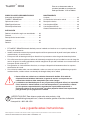
• The TrueDRY™ DR90/DR120 is designed to be installed indoors in a space that is protected from rain and
flooding.
• Install the unit with space to access the front panel for maintenance and service.
• Avoid directing the discharge air at people, or over the water in pool areas.
• If used near a pool or spa, be certain there is no chance the unit could fall into the water or be splashed, and
that it is plugged into a ground fault interrupt (GFI) outlet.
• To ensure quiet operation, do not place the device directly on the structural supports of the home.
• A drain pan must be placed under the unit if installed above a living area or above an area where water
leakage could cause damage.
1. Never operate a unit with a damaged power cord. If the power cord is damaged it must be
replaced by the manufacturer, its service agent, or similarly qualified person in order to
avoid a hazard.
2. The appliance is not intended for use by persons (including children) with reduced
physical, sensory, or mental capabilities, or lack of experience and knowledge, unless
they have been given supervision or instruction concerning use of the appliance by a
person responsible for their safety. Children should be supervised to ensure that they do
not play with the appliance.
!

AbouttheTrueDRY™DR90/DR120Dehumidier
The Honeywell TrueDRY DR90/DR120 ensures the home is maintained at proper humidity levels through its high
performance and efficiency.
When indoor humidity exceeds 60%,
the home is more susceptible to mold
and mildew growth. TrueDRY DR90/
DR120 safeguards against excessive
humidity in the home year-round.
*American Society of Heating, Refrigerating
and Air Conditioning Engineers (ASHRAE).
MCR24780
010203040506070809
0100
OPTIMUM
ZONE
BACTERIA
VIRUSES
FUNGI
MITES
RESPIRATORY
INFECTIONS
ALLERGIC RHINITIS
AND ASTHMA
CHEMICAL
INTERACTIONS
OZONE
PRODUCTION
ASHRAE RECOMMENDED WINTER DESIGN LEVEL
00159095808570756065505540453035202510150
001 4418312316210215110117014011019979593919
59 631031421811411
0117014011018969493919098878
09 221711311901601201001896959391909887868584838
58 801501201997959391909988
878685848382818089787
08 199888786868583828181808979787777767574737
57 0897978787777767675757474737372727
17079696
07 271717171717070707969686867676666656564646
WHAT THE AIR FEELS LIKE
HOW HOT THE HEAT-HUMIDITY COMBINATION MAKES IT FEEL.
EXAMPLE: AIR AT 90ºF WITH 50% RH FEELS LIKE 96ºF TO THE HUMAN BODY!
RELATIVE HUMIDITY (PERCENTAGE)
EXTREME DANGER
EXTREME CAUTION
CAUTION
M27328
DANGER
AIR TEMPERATURE
(DEGREES FAHRENHEIT)
SOURCE: TEMPERATURE - HUMIDIY INDEX WAS DERIVED BY R.G. STEADMAN, JOURNAL OF APPLIED METEOROLOGY, JULY 1979.
DR120
DR90
Benefits
• Removes up to 90 (DR90) or 120 (DR120) pints of water
per day from the indoor air
• Built-in fresh air supply
• Energy Star Rated
• Built-in transformer circuit breaker
Maintaining Ideal Humidity
Dew points and relative humidity (RH) affect the way your body
senses heat. Higher humidity levels cause the air to feel much
hotter than the actual temperature. When maintained properly,
your cooling equipment may not run as much because
dehumidified air feels cooler.
Ideal humidity is defined by industry experts* as being between
40-60% on an average annual basis.
TrueDry DR90/DR120 Dehumidication System 69-2690EFS—06
2

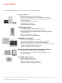
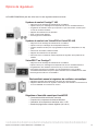
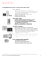
Control Options
The TrueDRY DR90/DR120 may be used with one of the following external controls:
HumidiPRO Digital Control
• Manual dehumidification control
• Dehumidifier compressor protection
• RH% and outdoor temperature calibration
• Adjustable high and low range stops (10-90%)
TrueIAQ Digital Control
• Automatic adjustments maintain fresh air in home.
• Sensor for displaying outdoor temperature and humidity.
• Advanced ventilation programming includes economizing and extreme
condition shutdown.
• Maintenance and service reminders.
• Controls other indoor air quality equipment.
Manual Dehumidistat and Automatic Ventilation Controls
• Manual humidity control with intuitive comfort settings.
• Automatic W8150 ventilation control to ASHRAE standard, or for
continuous operation.
Prestige™ IAQ Kit
• Controls both heating/cooling and ventilation.
• Wireless sensor for displaying outdoor temperature and humidity.
• Advanced ventilation programming includes economizing and extreme
condition shutdown.
• Maintenance and service reminders.
• High definition color display.
• RedLINK™ Wireless technology
VisionPRO™ or Prestige™
• Controls both heating/cooling and ventilation.
• Wireless sensor for displaying outdoor temperature and humidity.
• Ventilation programming for time of day or Ashrae standards.
• Optional ventilation lockouts for high/low temp or humidity conditions when
C7089R1013 wireless outdoor sensor is used.
• Wi-Fi™ or RedLINK™ Wireless technology
TrueDry DR90/DR120 Dehumidication System 69-2690EFS—06 3

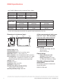
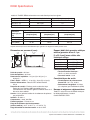
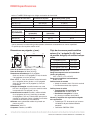
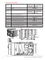
DR90Specications
Install TrueDRY DR90 according to National Electric Codes.
Dimensions in inches and (mm):
Product weight: 82 lbs.
Shipping weight: 93 lbs.
Shipping dimensions: 21.5”H x 18.5”W x 40.0”L
Media Filter: MERV 11, 14”H x 18”W x 2”L
Drain connection: 3/4-in. threaded female NPT connection.
Duct connections: 10-in. round inlet and outlet. 6-in. supply
inlet. ABS plastic, compatible for connection to rigid or
flexible ducting with sheet metal screws and/or tape.
Cabinet: 20 ga
Insulation: R value 1
Compressor: Rotary, 8.0k BTU
Refrigerant: R-410A, 21 oz
Operating Temp Range (outside cabinet):
34ºF to 135ºF (1.1ºC to 57.2ºC)
Operating Humidity Range: 0-99% RH
Input ratings
• Electrical input voltage: 120 VAC,
60 Hz nominal
• Input current: 5.9 A
Output ratings
• Power transformer to R/C
terminals: 24 VAC, 0.85 A
• Energy Performance: 2.9 liters
(6.1 pints) per kilowatt hour (KWH)
Standards and approval body
requirements
ETL Tested per standard UL 60335-2-40
ducted dehumidifier.
ENERGY STAR rated.
Dry-Bulb Temp Intake Humidity Capacity (Pints/Day)
80°F (26.7°C) 60% RH 97
70°F (21.1°C) 60% RH 74
60°F (15.6°C) 60% RH 55
Home Size
(square ft [m]) Dehumidifier Capacity Required to Maintain Desired Indoor RH*
60% RH Indoor
(pints/day) 50% RH Indoor
(pints/day) 40% RH Indoor
(pints/day)
2080 (193.2) 49–54 55–58 71–78
2600 (241.5) 61–68 65–72 90–97
3120 (289.9) 75–82 79–86 95–110
* Based on extreme climates where outdoor humidity is 70-90% RH. For less extreme climates, larger
homes can be adequately served with less capacity. Actual requirements may vary.
Airflow versus external static pres-
sure (0–1 in. [0 - 25.4 mm] water
pressure) with collars attached
0 in. (0 mm) 262 CFM
0.2 in. (5 mm) 225 CFM
0.4 in. (10 mm) 172 CFM
0.6 in. (15.2 mm) 106 CFM
3-3/16
(81)
3-3/16
(81)
19-3/8
(492)
14-3/8
(365)
25-13/16
(656)
M28840A
TrueDry DR90/DR120 Dehumidication System 69-2690EFS—06
4

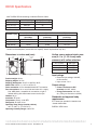
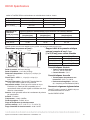
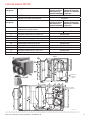
DR120Specications
Install TrueDRY DR120 according to National Electric Codes.
Dimensions in inches and (mm):
Product weight: 90 lbs.
Shipping weight: 101 lbs.
Shipping dimensions: 23.5”H x 18.5”W x 40.0”L
Media Filter: MERV 11, 14”H x 18”W x 2”L
Drain connection: 3/4-in. threaded female NPT connection.
Duct connections: 10-in. round inlet and outlet. 6-in. supply
inlet. ABS plastic, compatible for connection to rigid or
flexible ducting with sheet metal screws and/or tape.
Cabinet: 20 ga
Insulation: R value 1
Compressor: Rotary, 10.0k BTU
Refrigerant: R-410A, 26 oz
Operating Temp Range (outside cabinet):
34ºF to 135ºF (1.1ºC to 57.2ºC)
Operating Humidity Range: 0-99% RH
Input ratings
• Electrical input voltage: 120 VAC,
60 Hz nominal
• Input current: 7.3 A
Output ratings
•Power transformer to R/C
terminals: 24 VAC, 0.85 A
•Energy Performance: 2.9 liters
(6.1 pints) per kilowatt hour (KWH)
Standards and approval body
requirements
ETL Tested per standard UL 60335-2-40
ducted dehumidifier.
ENERGY STAR rated.
Dry-Bulb Temp Intake Humidity Capacity (Pints/Day)
80°F (26.7°C) 60% RH 121
70°F (21.1°C) 60% RH 92
60°F (15.6°C) 60% RH 72
Home Size
(square ft [m]) Dehumidifier Capacity Required to Maintain Desired Indoor RH*
60% RH Indoor
(pints/day) 50% RH Indoor
(pints/day) 40% RH Indoor
(pints/day)
2080 (193.2) 49–54 55–58 71–78
2600 (241.5) 61–68 65–72 90–97
3120 (289.9) 75–82 79–86 95–110
* Based on extreme climates where outdoor humidity is 70-90% RH. For less extreme climates, larger
homes can be adequately served with less capacity. Actual requirements may vary.
Airflow versus external static pres-
sure (0–1 in. [0 - 25.4 mm] water
pressure) with collars attached
0 in. (0 mm) 350 CFM
0.2 in. (5 mm) 285 CFM
0.4 in. (10 mm) 210 CFM
0.6 in. (15.2 mm) 150 CFM
25-13/16
(656)
21
(533)
19-3/8
(492)
M33292
14-3/8
(365) 3-3/16
(81)
3-3/16
(81)
TrueDry DR90/DR120 Dehumidication System 69-2690EFS—06 5

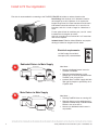
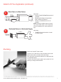
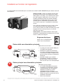
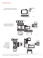
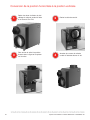
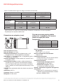
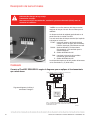
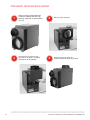
Install to Fit Your Application
Ideal when…
• Access to dedicated central return for
TrueDRY is available.
• Requires backdraft damper on the
exhaust port to minimize backdraft when
TrueDRY is not on but A/C is.
• (optional) Duct TrueDRY supply with 20%
open gravity damper to provide dry air to
a specific area
SUPPLY
RETURN
AIR HANDLER
TrueDRY
M33150
SEPARATE
RETURN
BACKDRAFT
DAMPER
(OPTIONAL)
GRAVITY DAMPER
ADedicated Return to Main Supply
DR120
DR90
TrueDry DR90/DR120 Dehumidication System 69-2690EFS—06
6
Flex duct is recommended in connecting to the TrueDRY DR90/DR120 collars to reduce vibration noise.
M24745
Electrical requirements:
115 VAC outlet. Ground fault
interrupter (GFI) recommended.
Duct Sizing: Use minimum 10-in. diameter round for
duct lengths up to 25 ft. Minimum 12-in. required for
lengths longer than 25 ft. Duct branches from the main
inlet/exhaust should be minimum 10-in. round for 2-3
branches, and 12-in. round or larger for 4 branches or
more.
For the optional fresh air ventilator port, use 6-in. round,
insulated duct for lengths up to 50 ft.
Use 8-in. round duct for more than 50 ft. of if more than
100 CFM is required.
Isolated Areas: Effective dehumidification may require
ducting to isolated or stagnant air flow areas.
SUPPLY
RETURN
AIR HANDLER
TrueDRY
M27324
BACKDRAFT
DAMPER
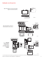
BMain Return to Main Supply
Ideal when…
• Running TrueDRY when not running A/C.
• Requires damper on the exhaust port to
minimize backdraft when TrueDRY DR90/
DR120 is not on but A/C is.
• Access to a dedicated central return is
not possible.

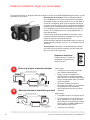
Ideal when…
• TrueDRY will not be ducted to a forced
air HVAC system.
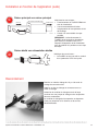
Attach 3/4” male NPT drain nozzle.
Connect 1/2-in. drain tube to male connection drain outlet.
Secure drain tube to connector with hose clamp.
Run drain hose continuously downhill to an approved drain
or condensate pump.
The drain line must include a water trap to prevent air from
entering or exiting the dehumidifier.
Plumbing
Install to Fit Your Application (continued)
TrueDry DR90/DR120 Dehumidication System 69-2690EFS—06 7
TrueDRY
M33152
SEPARATE
RETURN
SUPPLY
DDedicated Return to Dedicated Supply
SUPPLY
RETURN
AIR HANDLER
TrueDRY M27325
CMain Return to Main Return
Ideal when…
• Running TrueDRY DR90/DR120 with A/C
operation.
• Minimizing discharge air temperature
(DAT) increase is preferred.
• Access to a dedicated return is not
possible.
NOTE: Running TrueDRY after A/C shutoff
may cause excess water on A/C evaporator
coil to re-humidify air for a short amount of
time.

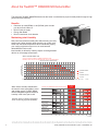
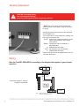
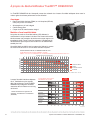
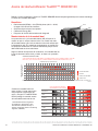
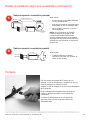
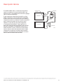
Terminal Description
* NOTE: The outer screws on the terminal block
secure the block to the chassis. They are not used
for wiring.
A wiring terminal block is located on the side panel
of the TrueDRY unit.
The six terminals for the terminal block (reading from
left to right in the photo) are:
FLOAT: External low voltage float switch or water
sensor (two terminals). Use normally
closed switch.
DHUM: Compressor and fan operation for
dehumidification
R: DR90/DR120 24V output
FAN: Fan activation only for ventilation
C: DR90/DR120 24V output
External 24V devices can be powered from R and C
terminals (20VA max.).
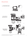
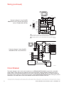
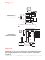
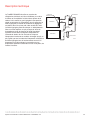
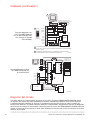
Wiring
Wire the TrueDRY DR90/DR120 according to the diagram that applies to your desired
operation.
TrueDry DR90/DR120 Dehumidication System 69-2690EFS—06
8
TrueDRY
HVAC
THERMOSTAT
GYWR C
M29839A
C
Rc
R
H
H
DH
DH
W
W2
Y
Y2
G
K
NO
TE: THERMOSTAT MUST BE CONFIGURED TO DRIVE FURNACE FAN
DURING DEHUMIDIFICATION CALL.
DHUM
+
+
RFANC
FLOAT
Follow this diagram if using the
Prestige™ thermostat.
CAUTION: Low voltage hazard.
Can cause equipment damage.
Disconnect HVAC equipment before beginning installation.

Wiring (continued)
TrueDry DR90/DR120 Dehumidication System 69-2690EFS—06 9
Follow this diagram for
ducted operation with an
external humidity control.
Follow this diagram if using the
HumidiPro Digital Humidity Controller.
HVAC
MECHANICAL
DEHUMIDISTAT
THERMOSTAT
GYWRRc
GYWR C
M29840A
DRY
CONTACTS
DPDT RELAY,
2.6A
TrueDRY
DHUM
+
+
RFANC
FLOAT FLOAT
Follow this diagram for
ducted operation with
external humidity and
ventilation control.
TrueDRY
HVAC
MECHANICAL
DEHUMIDISTA
T
THERMOSTAT
GY
W
RRc
GYWR C
M29841A
DRY
CONTACTS
DPDT
RELAY,
2.6A
EARD6TZ
AT120
R
C
DAMPER
AUX
REMOTE
W8150A
G
R
C
C
W
G
DHUM
+
+
RFANC
FLOAT
M34595
C
R
U
U
S
S
24 VAC
(CONSTANT)
RFloat DHUM FanC

Wiring (continued)
Follow this diagram if using TrueDRY
DR90/DR120 with a powered dehumidistat
such as TrueIAQ (DG115EZIQ).
HVAC
THERMOSTAT
GYWRRc
M29842A
IF A THERMOSTAT OTHER THAN A TH5110, TH5220, TH5320, TH6110, TH6220, TH6320,
TH8110, TH8320, OR TH8321 IS USED, A RELAY MAY BE REQUIRED TO ISOLATE THE G WIRE.
PROGRAM ISU SETTING 60 TO Ø TO FORCE SYSTEM FAN ON WITH DEHUMIDIFICATION CALL.
C
68
40
55
12 15
:
76
%
%
In
Out
PM
R
C
W
Y
G
R
C
SENSOR
SENSOR
SWITCH
W
G
VENT
VENT
DEHUM
DEHUM
HUM
HUM
OUTDOOR
SENSOR
(PROVIDED)
EARD6TZ
TrueIAQ
1
1
2
2
TrueDRY
DHUM
+
+
RFANC
FLOAT
To prevent damage to the 24 volt control transformer, the DR90A2000/DR120A2000 comes with a resettable
circuit breaker. Check wiring for any electrical short and repair before resetting breaker. Resetting the circuit
breaker without correcting the electrical short may result in transformer damage. Be sure to check the electrical
schematics in this manual or inside the access panel of the DR90A2000/DR120A2000 before making any control
connections. The reset button for the circuit breaker can be found on the back of the unit.
Circuit Breaker
TrueDry DR90/DR120 Dehumidication System 69-2690EFS—06
10
Follow this diagram if using TrueDRY
DR90/DR120 with a VisionPRO IAQ.
M29843A
FAN
FURNACE BOARD
EQUIPMENT INTERFACE MODULE (EIM)
G
C
CONV.HP
1
2
3
C
R
RC
RH
W1
W2
W3
Y
Y2
G
O/B
AUX
AUX2
Y
Y2
G
H1
U
M2
D1
H
M2
V1
N
T2
HEAT 1 RELAY
HEAT 2 RELAY
HEAT 3 RELAY
COOL 1 RELAY
COOL 2 RELAY
FAN RELAY
VISIONPRO IAQ
D-1
R-2
C-3
FLOAT
FLOAT
DHUM
R
FAN
C
OR
EARD6TZ
TrueDRY
+
+

Cleaning
Apply power to TrueDRY DR90/DR120. Turn the humidity control to a low RH% level to initiate a dehumidifica-
tion call. Confirm that the TrueDRY DR90/DR120 compressor and fan turn on. The furnace blower will also turn
on to circulate air. This will take up to two minutes. Be sure to turn the control to the desired RH% or to Off when
checkout is complete.
Checkout
TrueDry DR90/DR120 Dehumidication System 69-2690EFS—06 11
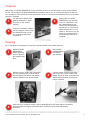
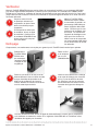
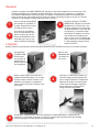
On an annual basis, maintenance is required to ensure TrueDRY runs at peak efficiency.
1
1
2
2
3
3
4
Unplug TrueDRY
DR90/DR120
before beginning
service. Remove
the magnetic filter
door.
Cut and remove plastic strap
holding compressor in place.
This strap is only used for
shipping.
Remove filter
(50049536-003)
and replace
with new filter.
Apply power to TrueDRY
DR90/DR120. Turn humidity
control to a low RH% to initi-
ate a dehumidification call.
Confirm that the compressor
and fan turn on. The furnace
blower will also turn on to cir-
culate air. Be sure to turn the
control to the desired RH% or
to Off when the checkout is
complete.
Remove cover on output side of dehumidi-
fier. Using a damp cloth, remove excess
dust and debris from blower and internal
cabinet. Reattach cover when finished.
If using for ventilation, initiate a
call for ventilation. Confirm that
the DR90/DR120 fan turned
on, but that the compressor
remained off.
5
When service is complete, initiate a call for dehumidification and check that the compressor
and fan activate. If using the VisionPRO IAQ or TrueIAQ controls, reset maintenance
reminders.
Check the drain connection and drain
line to ensure it is clear of debris and
sludge. Ensure all hose connections are
secure once maintenance of the drain
lines is complete.

TrueDry DR90/DR120 Dehumidication System 69-2690EFS—06
12
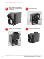
Horizontal to Vertical Conversion
2Remove the duct collar.
3Rotate the collar to the position shown
in the figure and place it back on the
cabinet. 4Reattach the duct collar using the
twelve screws.
Remove the twelve screws attached to the
wiring side of the duct collar using a T25
Torx screwdriver.
1

TrueDry DR90/DR120 Dehumidication System 69-2690EFS—06 13
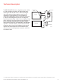
Technical Description
TrueDRY DR90/DR120 uses a refrigeration system similar
to an air conditioner to remove heat and moisture from
incoming air and add heat to the air that is discharged.
Hot, high-pressure refrigerant gas is routed from the
compressor to the condenser coil. The refrigerant is
cooled and condensed by giving up its heat to the air that
is about to be discharged from the unit. The refrigerant
liquid then passes through a filter drier and capillary tubing
which causes the refrigerant pressure and temperature to
drop. It next enters the evaporator coil where it absorbs
heat from the incoming air and evaporates. The evaporator
operates in a flooded condition, which means that all the
evaporator tubes contain liquid refrigerant during normal
operation. A flooded evaporator should maintain nearly
constant pressure and temperature across the entire coil,
from inlet to outlet.
CONDENSER
EVAPORATOR
CAPILLARY
TUBES
ACCUMULATOR
COMPRESSOR
STRAINER/FILTER
DRIER
M27404

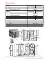
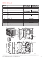
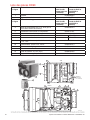
DR90 Parts List
M34305A
1
2
TOP
SIDE
15
12
6
14
7
8
5
10
9
11
4(INSIDE
CONTROL
BOX)
TrueDry DR90/DR120 Dehumidication System 69-2690EFS—06
14
Figure
Reference Base and Accessory Parts Part Number
(device date code
up to K12XXXXX)
Part Number
(device date code
L12XXXXX and up)
1TrueDRY DR90A2000/U
2Motorized Ventilation Damper EARD6TZ
Figure
Reference Replacement Parts Part Number
(device date code
up to K12XXXXX)
Part Number
(device date code
L12XXXXX and up)
4Compressor Relay, 24 VAC, 30 A (found in control
box) 50035445-014
5Compressor Run Capacitor 50070171-001
610" Duct Collar 50049536-005
7Fan Assembly 50049537-006 DR90XFAN1
8Capacitor - Fan 50070204-001 DR90XCFA1
9Fan Relay, SPDT, 24 VAC, 15A 50035445-011
10 Transformer 120/24 VAC, 40 VA 50035445-013
11 Defrost Thermostat 50070204-002
12 Filter 50070171-002
14 6” Duct Collar 50049536-004
15 Magnetic Filter Door 50070171-003

TrueDry DR90/DR120 Dehumidication System 69-2690EFS—06 15
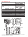
DR120 Parts List
Figure
Reference Base and Accessory Parts Part Number
(device date code
up to K12XXXXX)
Part Number
(device date code
L12XXXXX and up)
1TrueDRY DR120A2000/U
2Motorized Ventilation Damper EARD6TZ
Figure
Reference Replacement Parts Part Number
(device date code
up to K12XXXXX)
Part Number
(device date code
L12XXXXX and up)
4Compressor Relay, 24 VAC, 30 A (found in control
box) 50035445-014
5Compressor Run Capacitor 50070205-001 DR120XCRC1
610" Duct Collar 50049536-005
7Fan Assembly 50070205-002
8Capacitor - Fan 50070205-003
9Fan Relay, SPDT, 24 VAC, 15A 50035445-011
10 Transformer 120/24 VAC, 40 VA 50035445-013
11 Defrost Thermostat 50070204-002
12 Filter 50070171-002
14 6” Duct Collar 50049536-004
15 Magnetic Filter Door 50070171-003
M34306A
1
2
TOP
SIDE
15
14
11 7510 9
8
VIEW OF CONTROL BO
X
WITH COVER REMOVED
12
6
4(INSIDE
CONTROL
BOX)

® U.S. Registered Trademark
© 2016 Honeywell International Inc.
69-2690EFS—06 M.S. Rev. 12-16
Printed in U.S.A
In the U.S.:
Honeywell
1985 Douglas Drive North
Golden Valley, MN 55422
http://yourhome.honeywell.com
Home and Building Technologies
Honeywell warrants this product to be free from defects in the workmanship or materials, under normal use and
service, for a period of five (5) years from the date of purchase by the consumer. If at any time during the war-
ranty period the product is determined to be defective or malfunctions, Honeywell shall repair or replace it (at
Honeywell’s option).
If the product is defective,
(i) return it, with a bill of sale or other dated proof of purchase, to the place from which you purchased it; or
(ii) call Honeywell Customer Care at 1-800-468-1502. Customer Care will make the determination whether
the product should be returned to the following address: Honeywell Return Goods, Dock 4 MN10-3860, 1985
Douglas Dr. N., Golden Valley, MN 55422, or whether a replacement product can be sent to you.
This warranty does not cover removal or reinstallation costs. This warranty shall not apply if it is shown by
Honeywell that the defect or malfunction was caused by damage which occurred while the product was in the
possession of a consumer.
Honeywell’s sole responsibility shall be to repair or replace the product within the terms stated above.
HONEYWELL SHALL NOT BE LIABLE FOR ANY LOSS OR DAMAGE OF ANY KIND, INCLUDING ANY
INCIDENTAL OR CONSEQUENTIAL DAMAGES RESULTING, DIRECTLY OR INDIRECTLY, FROM ANY
BREACH OF ANY WARRANTY, EXPRESS OR IMPLIED, OR ANY OTHER FAILURE OF THIS PRODUCT.
Some states do not allow the exclusion or limitation of incidental or consequential damages, so this limitation
may not apply to you.
THIS WARRANTY IS THE ONLY EXPRESS WARRANTY HONEYWELL MAKES ON THIS PRODUCT. THE
DURATION OF ANY IMPLIED WARRANTIES, INCLUDING THE WARRANTIES OF MERCHANTABILITY AND
FITNESS FOR A PARTICULAR PURPOSE, IS HEREBY LIMITED TO THE FIVE-YEAR DURATION OF THIS
WARRANTY. Some states do not allow limitations on how long an implied warranty lasts, so the above limitation
may not apply to you.
This warranty gives you specific legal rights, and you may have other rights which vary from state to state.
If you have any questions concerning this warranty, please write Honeywell Customer Relations, 1985 Douglas
Dr, Golden Valley, MN 55422 or call 1-800-468-1502.
5-Year Limited Warranty

TrueDRY™ DR90/DR120
BESOIN D’AIDE? Pour obtenir de l’aide sur ce produit, prière de visiter le site
http://forwardthinking.honeywell.com ou d’appeler le service d’assistance à la clientèle de
Honeywell au 1-800-468-1502.
Lire et conserver ces instructions.
® Marque de commerce déposée aux États-Unis. Brevets en instance. Copyright © 2016 Honeywell International Inc. Tous droits réservés.
Système de déshumidication TrueDRY™ DR90 69-2690EFS—06 17
?
À PROPOS DU NOUVEAU DÉSHUMIDIFICATEUR
Àproposdudéshumidicateur
TrueDRY™ DR90/DR120 .................... 18
Options de régulateurs ...................... 19
DR90Spécications ........................ 20
DR120Spécications ....................... 21
INSTALLATION
Installation en fonction de l’application .......... 22
Raccordement ............................. 23
Description des bornes ...................... 24
Câblage ................................. 25
Vérication ................................ 27
ENTRETIEN
Nettoyage ................................ 27
Conversion de la position horizontale
à la position verticale ........................ 28
Description technique ....................... 29
Liste des pièces DR90 ....................... 30
Liste des pièces DR120 ...................... 31
Garantie limitée de 5 ans ..................... 32
• Le modèle TrueDRY™ DR90 est destiné à être installé à l’intérieur dans un lieu protégé de la pluie et des
inondations.
• Installer l’unité en assurant le dégagement nécessaire pour l’accès au panneau pour la maintenance et
l’entretien.
• Éviter de diriger l’air d’évacuation vers les personnes ou sur l’eau des piscines.
• Si le produit est utilisé près d’une piscine ou d’un spa, veiller à garantir que l’unité ne peut pas tomber dans
l’eau ou être éclaboussée, et qu’elle est raccordée à un disjoncteur de fuite à la terre.
• Pour garantir un fonctionnement silencieux, ne pas placer l’unité directement sur les supports de structure du
bâtiment.
• Un bac de récupération doit être placé sous l’unité si elle est installée au-dessus d’une zone habitée ou
d’une zone où une fuite d’eau pourrait causer des dommages.
1. Ne jamais faire fonctionner l’appareil avec un cordon d’alimentation endommagé. Si le
cordon d’alimentation est endommagé, il doit être remplacé par le fabricant, son agent du
service, ou une personne qualifiée afin d’éviter les situations dangereuses.
2. Cet appareil n’est pas conçu pour une utilisation par des personnes (incluant les
enfants) ayant des capacités physiques, sensorielles ou mentales réduites, ou manquant
d’expérience et de connaissance à moins d’avoir reçu la supervision ou les instructions
concernant l’utilisation de l’appareil par une personne responsable de leur sécurité. Les
enfants devraient être supervisés pour s’assurer qu’ils ne jouent pas avec l’appareil.
!
Il s'agit d'un document produit hérité pris en
charge par Resideo. Il n'est plus fabriqué.

ÀproposdudéshumidicateurTrueDRY™DR90/DR120
Le TrueDRY DR90/DR120 de Honeywell permet de maintenir les niveaux d’humidité adéquats dans toute la
maison grâce à sa haute performance et son efficacité.
Lorsque l’humidité intérieure dépasse
60 %, l’habitation est plus suscep-
tible à la moisissure. L’unité TrueDRY
DR90/DR120 protège de l’humidité
excessive dans la maison tout au long
de l’année.
* Société américaine des ingénieurs en
chauffage, refroidissement et climatisation
(ASHRAE).
MFCR24780
010203040506070809
01
00
ZONE
OPTIMALE
BACTÉRIES
VIRUS
CHAMPIGNONS
ACARIENS
INFECTIONS
RESPIRATOIRES
RHINITES ALLERGIQUES
ET ASTHME
INTERACTIONS
CHIMIQUES
PRODUCTION
D’OZONE
TAUX D’HUMIDITÉ TYPE EN HIVER
RECOMMANDÉ PAR L’ASHRAE
00159095808570756065505540453035202510150
001 4418312316210215110117014011019979593919
59 631031421811411
0117014011018969493919098878
09 221711311901601201001896959391909887868584838
58 801501201997959391909988
878685848382818089787
08 199888786868583828181808979787777767574737
57 0897978787777767675757474737372727
17079696
07 271717171717070707969686867676666656564646
NOTRE PERCEPTION DE LA TEMP
É
RATURE DE L’AIR
NOTRE PERCEPTION DE LA CHALEUR COMBINÉE À L’HUMIDITÉ
EXEMPLE : À 90 °F ET 50 % D’HUMIDITÉ RELATIVE, LA TEMPÉRATURE PERÇUE PAR NOTRE CORPS ATTEINT 96 °F!
HUMIDITÉ RELATIVE (POURCENTAGE)
DANGER EXTRÊME
PRUDENCE EXTRÊM
E
PRUDENCE
MF27328
DANGER
TEMP
É
RATURE DE L’AIR
(DEGRÉ FAHRENHEIT)
SOURCE : INDICE DE TEMPÉRATURE-HUMIDITÉ DÉRIVÉ PAR R.G. STEADMAN, JOURNAL OF APPLIED METEOROLOGY, JUILLET 1979.
Avantages
• Retire jusqu’à 90 chopines (DR90) ou 120 chopines (DR120)
d’eau par jour de l’air intérieur.
• Alimentation en air frais intégrée
• Certifié Energy Star
• Coupe-circuit du transformateur intégré
Maintien d’une humidité idéale
Les points de rosée et d’humidité relative (HR) affectent la
manière dont le corps ressent la chaleur. Des niveaux d’humidité
élevés causent une perception de chaleur accrue par rapport à la
température réelle. Lorsqu’il est bien entretenu, l’équipement de
refroidissement peut ne pas tourner autant car l’air déshumidifié
semble plus frais.
L’humidité idéale est définie par les experts de l’industrie* comme
se situant entre 40 et 60 % sur une base annuelle moyenne.
DR120
DR90
Système d’humidication TrueDRY DR90/DR120 69-2690EFS—06
18
La page est en cours de chargement...
La page est en cours de chargement...
La page est en cours de chargement...
La page est en cours de chargement...
La page est en cours de chargement...
La page est en cours de chargement...
La page est en cours de chargement...
La page est en cours de chargement...
La page est en cours de chargement...
La page est en cours de chargement...
La page est en cours de chargement...
La page est en cours de chargement...
La page est en cours de chargement...
La page est en cours de chargement...
La page est en cours de chargement...
La page est en cours de chargement...
La page est en cours de chargement...
La page est en cours de chargement...
La page est en cours de chargement...
La page est en cours de chargement...
La page est en cours de chargement...
La page est en cours de chargement...
La page est en cours de chargement...
La page est en cours de chargement...
La page est en cours de chargement...
La page est en cours de chargement...
La page est en cours de chargement...
La page est en cours de chargement...
La page est en cours de chargement...
La page est en cours de chargement...
La page est en cours de chargement...
La page est en cours de chargement...
-
 1
1
-
 2
2
-
 3
3
-
 4
4
-
 5
5
-
 6
6
-
 7
7
-
 8
8
-
 9
9
-
 10
10
-
 11
11
-
 12
12
-
 13
13
-
 14
14
-
 15
15
-
 16
16
-
 17
17
-
 18
18
-
 19
19
-
 20
20
-
 21
21
-
 22
22
-
 23
23
-
 24
24
-
 25
25
-
 26
26
-
 27
27
-
 28
28
-
 29
29
-
 30
30
-
 31
31
-
 32
32
-
 33
33
-
 34
34
-
 35
35
-
 36
36
-
 37
37
-
 38
38
-
 39
39
-
 40
40
-
 41
41
-
 42
42
-
 43
43
-
 44
44
-
 45
45
-
 46
46
-
 47
47
-
 48
48
-
 49
49
-
 50
50
-
 51
51
-
 52
52


Honeywell DR90/DR120 90 Pint Whole House Dehumidifier Guide d'installation
- Taper
- Guide d'installation
dans d''autres langues
Documents connexes
-
Honeywell Dehumidifier DR90 Manuel utilisateur
-
Honeywell DR65 Manuel utilisateur
-
-
Honeywell C7089R3013 Guide d'installation
-
-
Honeywell VNT5150H1000 Manuel utilisateur
-
-
Honeywell HM506 Guide d'installation
-
Honeywell TrueSTEAM HM506 Manuel utilisateur

