La page est en cours de chargement...

Installation Instructions | Installationsanleitung |
Notice d’installation | Istruzioni per l’installazione |
Instrucciones de instalación
Minebea Intec Combics: Option Y2
Models CAIS… | CAW.S… | CAAP…
Combics Equipment for Use in Zone 2 and 22 Hazardous Areas
Modelle CAIS… | CAW.S… | CAAP…
Combics-Geräte für den Einsatz in explosionsgefährdeten Bereichen der Zonen 2 und 22
Modèles CAIS… | CAW.S… | CAAP…
Appareils Combics pour l’utilisation dans les domaines à risques d’explosions des zones 2 et 22
Modelli CAIS… | CAW.S… | CAAP…
Strumenti Combics per l’impiego nelle aree a rischio di esplosione, Zona 2 e 22
Modelos CAIS… | CAW.S… | CAAP…
Aparatos Combics para el empleo en atmósferas potencialmente explosivas, zonas 2 y 22
98647-004-70

2 Installation Instructions Option Y2 Installation Instructions Option Y2 3
Contents
Contents
English – page 2
In cases involving questions of interpretation,
the German-language version shall prevail.
Deutsch – Seite 10
Im Auslegungsfall ist die deutsche Sprache
maßgeblich.
Français – page 18
En cas de questions concernant l’interprétation,
la version en langue allemande fera autorité.
Italiano – pagina 26
In caso di interpretazione, fa testo la
versione in lingua tedesca.
Español – página 34
En caso de interpretación, la versión en
lengua alemana es determinante.
Intended Use ....................................... 3
Warning a nd Safety Information ........................ 3
Getting Started...................................... 4
Safety Instructions ................................... 6
EC Declaration of Conformity ...........................42
Manufacturer’s Certificate..............................44

2 Installation Instructions Option Y2 Installation Instructions Option Y2 3
Warning and Safety Information
Intended Use
Combics explosion-protected instru-
ments equipped with Option Y2 meet
the requirements for Category 3
equipment in accordance with Council
Directive 94/9/EC and are rated for
use in Zone 2 and 22 hazardous areas.
Please refer to the Annex to the
Statement of Conformity for the
equipment designation.
The permissible temperature range
during operation is –20°C to +40°C
(–4°F to +104°F).
The additional equipment required
was installed by Minebea Intec during
the production process.
The weighing instrument meets the EC
Directives and standards governing:
– electrical apparatus
– explosion protection
– electromagnetic compatibility
– electrical safety
Improper use or handling, however, can
result in damage and/or injury.
– Do not expose the equipment to aggressive
chemical vapors or to extreme tempera-
tures, moisture, shocks, or vibration.
The equipment is rated for use in Zone 2
and 22 hazardous areas. Please make sure
the currently valid regulations and guide-
lines for installing equipment in the areas
listed above are strictly observed.
– When using the equipment in hazard-
ous areas, make sure there is no current
or voltage in the equipment before con-
necting or disconnecting current-carrying
cables to or from the device. Disconnect
the scale from AC power before connecting
or disconnecting cables.
– Refer to the enclosed “Installation
Instructions“ before installing the equip-
ment: Drawing 65954-751-16-A4
– Installation in a Zone 2 or 22 hazardous
area must be performed by a trained
technician. The power connection must be
made in accordance with the regulations
applicable in your country.
If you need assistance, contact your
Minebea Intec dealer or the Minebea Intec
Service Center. Any installation work that
does not conform to the instructions in
this manual will result in forfeiture of all
claims under the manufacturer‘s warranty.
– Make sure all metal parts are grounded to
prevent buildup of static electricity.
– Have the equipment inspected at appropri-
ate intervals for correct functioning and
safety by a trained technician.
– If you see any indication that the equip-
ment cannot be operated safely (for
example, due to damage), disconnect the
device from power and lock the equipment
in a secure place so that it cannot be used
for the time being. Make sure the appli-
cable accident prevention regulations are
observed by all operating personnel.
– Always make sure the equipment is discon-
nected from AC power before performing
any installation, cleaning, maintenance or
repair work.
– Handle the equipment with care in accor-
dance with its IP protection rating. Make
sure the IP protection is not damaged
when cleaning the equipment.
– If you use cables purchased from another
manufacturer, check the pin assignments
in the cable against those specified by
Minebea Intec before connecting the cable
to Minebea Intec equipment, and discon-
nect any wires that are assigned differ-
ently. The
operator shall be solely responsible for any
damage or injuries that occur when using
cables not supplied by Minebea Intec.
Conditions for Installation:
Before putting the equipment into opera-
tion, it is important to make sure that the
power cord is correctly connected to the
power outlet (mains supply). All equip-
ment must be connected to the equipoten-
tial bonding conductor by connecting the
grounding cable (not included in delivery)
to the grounding terminals or bore holes
provided for this purpose on each device.
The dimensions of the grounding cable
are specified in national regulations for
electrical installations. Installation must
be performed by a trained technician in
accordance with national regulations and
acknowledged technological standards.
Use only cabling and extensions approved
by Minebea Intec, as these are made in
accordance with the restrictions on permis-
sible cable lengths imposed by both the
capacitance and inductivity values and
the requirements for electromagnetic
compatibility.
Before putting the weighing system into
operation for the first time, make sure
there is no hazard of explosion present
at the place of installation. If there is any
indication that the equipment does not
function properly (e.g., display remains
blank) due to damage during transport,
disconnect the equipment from power and
notify your nearest Minebea Intec Service
Center.
Before connecting or disconnecting data
cables, control lines or measuring lines to
or from the device, make sure all equip-
ment is disconnected from power.
If the equipment housing is opened by
anyone other than persons authorized by
Minebea Intec, this will negate its confor-
mity with regulations governing use in the
stated Zone 2 and
22 hazardous areas and result in forfeiture
of all claims under the manufacturer‘s
warranty.
DeviceNet YDO02C-DN (B3) use only with
stainless steel cable gland. The shielding of
the bus cable is not connected to the
device!
If you use the equipment in a hazardous
area outside Germany, you must comply
with the national electrical code and appli-
cable safety regulations of your
country. Ask your local Minebea Intec
office
or dealer for information on the legal
regulations applicable in your country.
Warning and Safety Information

4 Installation Instructions Option Y2 Installation Instructions Option Y2 5
Getting Started
Getting Started
If necessary, connect the weighing platform (not applicable to Combics CAW.S..
complete scales):
$ See the operating instructions supplied with the particular indicator.
Connect the equipment to AC power:
$ See the operating instructions supplied with the particular Combics indicator.
$ Min. torque that must be applied the cable gland when connecting the equipment
to AC power: 3 Nm
$ Min. torque for other cable glands: 5 Nm
Connect an equipotential bonding conductor (CAIS indicators and CAW.S..
complete scales) = grounding:
§ Connect the device to a central equipotential bus bar (not included in delivery) using
a grounding conductor.
§ If necessary, seal the Combics indicator to protect it from vapors as follows:
– Use a torque wrench
– Apply 1 Nm torque to each of the 10 screws
§ Make sure the integrity of the IP67/IP69K protection is not damaged or impaired while
performing installation work. For more information about industrial protection,
contact the Minebea Intec Service Center.

4 Installation Instructions Option Y2 Installation Instructions Option Y2 5
Getting Started
CAAPS... and CAAPP... weighing platforms must be grounded using an equipotential
bonding conductor (grounding):
§ Make sure all metal parts are grounded to prevent buildup of static electricity.
Connect the device to a central equipotential busbar (not included in delivery) using
a grounding conductor.
§ Tighten screws and nuts securely.
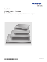
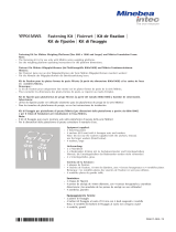
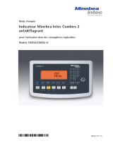
CAAPS1.. and CAAPP1.. weighing platforms, dimensions: up to 500 + 400 mm
CAAPS1.. and CAAPP1.. weighing platforms, dimensions: > 650 + 500 mm
CAAPS4.. and CAAPP4.. weighing platforms

6 Installation Instructions Option Y2 Installation Instructions Option Y2 7
Safety Information
Page 4
of
1
65954-750-16
Safety Information
11.05.2012
Klausgrete Drawing No.
Designation
Revision 01
1. Mains Connection
Explosion-risk area Zone 2 or Zone 22Explosion-safe area
Indicator CAIS.
or
complete scale
CAW...-......-......
each with option Y2
2. Data Transfer
PC,
Printer,
PLC,
etc.
For data transfer only and, if required, supply for the connected
device (e.g. printer), there is no supply voltage going from the
connected device to the indicator / complete scale
These devices may also be
installed in Zone 2 or Zone 22
if they are suitable for
Category 3 as per the ATEX
Directive.
Gas: Group IIC, temperature class T4
Dust: Group IIIC, Tmax 80°C
Ambient temperature: -10°C … +40°C …
Protect connector from
equipment supplied from
being disconnected. Make
sure the emergency stop
works.
Connector from
equipment
supplied
Connection
alternatives
Use an explosion-protected connector
Equipotential
bonding conductor
Equipotential
bonding conductor
Note 8)
EX
Indicator CAIS.
or
complete scale
CAW...-......-......
each with option Y2
Note 8)
Note 16)

6 Installation Instructions Option Y2 Installation Instructions Option Y2 7
Safety Information
Page 4
of
2
65954-750-16
Safety Information
11.05.2012
Klausgrete Drawing No.
Designation
Revision 01
Analog weighing
platforms from series
CAAP..-......-...... +
Option Y2 or other weighing
platforms suitable for Zone 2
or 22 (category 3G or 3D) that
can be supplied via a bridge
supply voltage of at least
9 VDC (±4.5 VDC).
ADU output with
bridge supply voltage
9 VDC (±4.5 VDC)
3. Connecting Weighing Platforms
4. Connecting External Devices
Equipotential
bonding conductor
Equipotential
bonding conductor
Indicator
CAIS. with option Y2
Analog weighing platforms (load cells)
of series
CAAP..-......-...... + Option Y2
Connection
alternatives
Explosion-safe area
Note 8)
Note 8)
Note 8)
Note 8)
Note 8)
External device with
bridge supply voltage
12 VDC (±6.0 VDC)
External device with
bridge supply voltage
12 VDC (±6.0 VDC)
Device must be
suitable for Zone
2 and/or 22!
Digital weighing
platforms that are
suitable for Zone 2 or 22
(category 3G or 3D) and
can be supplied by at
least 16 VDC via the
data output.
Data output with
nominal supply
voltage
16 VDC
Note 8)
Explosion-risk area Zone 2 or Zone 22
Gas: Group IIC, temperature class T4
Dust: Group IIIC, Tmax 80°C
Ambient temperature: -10°C … +40°C

8 Installation Instructions Option Y2 Installation Instructions Option Y2 9
Safety Information
Page 4
of
3
65954-750-16
Safety Information
11.05.2012
Klausgrete Drawing No.
Designation
Revision 01
These safety instructions apply to installation, use, maintenance and repair
1. The device (CAIS. indicator, CAAP weighing platform..-……-……, CAW complete scale…-……-…...)
is suitable for use in potentially explosive atmospheres of Zone 2 (Group IIC, temperature
class T4 or T6 for weighing platforms) and Zone 22 (Group IIIC; surface temperature 80°C)
according to EU Directive 94/9/EC and applicable harmonized European standards. This does
not guarantee compliance with other properties and requirements.
2. The device may only be used indoors.
3. Do not use it as a portable instrument.
4. Installation, operation, maintenance and repairs should only be performed by an authorized
specialist, in accordance with applicable laws, rules and regulations, ordinances and standards.
Particular attention should be paid to Standard EN 60079-14 within the scope of validity of EU
Directive 94/9/EC for the installation. Installation, maintenance, cleaning and repair work may
only take place with all power disconnected from the device and any connected peripheral
devices.
5. It is essential that recommendations on the installation, operation, maintenance and repair
contained in the operating instructions supplied are complied with for all equipment (including
connected devices). The temperature ranges of connected devices must also be taken into
account.
6. The device should only be used in a temperature range of -10°C … +40°C, do not expose it to
unacceptable sources of heat or cold, direct sunlight, UV radiation, shocks or vibrations, and the
installation should ensure that heat can be properly dissipated and external heat sources are
kept at a sufficient distance.
7. Tighten the cable entry glands using a torque of 5 Nm. The cable gland for the power cord should
be tightened with a torque of only 3 Nm. Install the external connecting cables firmly to avoid
damage and strain. The cable connections inside the explosion-risk area must be secured
against loosening.
8. All metal parts must be electrically connected to the same equipotential bonding conductor (PA)
so that any electrostatic charges can be conducted away from the equipment. For this purpose,
the equipment operator is obligated to connect a lead with a gauge of at least 4 mm² (cross
section) to the equipotential bonding terminal (indicated by the ground symbol) located on the
housing. A suitable ring terminal must be attached to the end of the cable. The cable must be laid
so that the ground connector cannot come loose. The connection to the equipotential bonding
conductor should be checked to see if it is of low resistance at the time of installation and at
regular intervals. The indicator and weighing platform must each be connected individually to the
equipotential bonding conductor if no metal connection (e.g. support arm) is used between them.
Do not use the shield of the connection cable for the equipotential bonding conductor.
9. Before opening devices, switch off the supply voltage, or make sure that the area is not
potentially explosive. Do not connect or disconnect any live cables inside an explosion-risk area.
10. When closing, make sure the cover screws are tightly secured.
11. The device should only be operated for the first time when it is certain that the area is not
potentially explosive.
12. Data lines to connected devices and the connection cable to the weighing platform should be
secured against accidental disconnection and may only be connected and disconnected when
the power supply is turned off. Block unused outlets to guarantee the IP 65 level of protection.
Keep any transitory voltage phenomenon away from the device.
13. Data cables are for data transfer only and may not supply any power from the connected device
to the indicator / complete scale. However, one digital weighing platform suitable for use in Zone
2 or 22 connected to the data output can be supplied via direct voltage if it can be supplied by
direct voltage of at least 16 VDC via the data output.

8 Installation Instructions Option Y2 Installation Instructions Option Y2 9
Safety Information
Page 4
of
4
65954-750-16
Safety Information
11.05.2012
Klausgrete Drawing No.
Designation
Revision 01
14. During installation, take suitable steps to prevent stray electrical interference (e.g. due to
magnetic fields). Keep any voltage transients away from the device.
15. The indicator (indicator of the complete scale) should be installed so that there is only a low risk
of mechanical danger to the IP protection. The IP protection rating of the device is IP6x according
to EN 60529 / IEC 60529. The device is designed for clean environments and must be handled
carefully according to the IP protection rating.
16. The power connection must be made in accordance with the regulations applicable in the country
of operation. A correct power connection must be ensured. The power supply cable should be
protected against damage and properly connected to the power supply (100 - 240 VAC, ± 10%,
50-60Hz) or 24 VDC (± 10%) for Option L8.The indicator and/or complete scale is approved for
circuits up to 1500 A. Only use the power supply connection cable in the hazardous area with a
suitable and approved explosion-protected plug. Alternatively: Protect connector from being
disconnected or attach the power supply connection cable directly. Be sure to provide a suitable
emergency shut-off switch.
17. Avoid generating static electricity. Only use a damp cloth to clean the device. This is especially
true when using a dust cover. The equipment operator assumes responsibility for preventing any
risks caused by electrostatic charging.
18. If cables are connected subsequently, make sure that the connections are not corroded. The
grounding conductor of a mains connection cable must have the same cross section as the
current-carrying wires (N and L).
19. All external cables (even cables between load cells / weigh cells and connection box / junction
box) are only suitable for fixed placement and must be laid fixed. Otherwise, use screwed
connections designed according to EN60079-0 and rounded at an angle of 75º (minimum) and a
radius at least equal to one-quarter of the diameter of the cables, but without exceeding 3 mm.
20. Cables from third-party manufacturers (subject to the user’s responsibility) must be tested for
suitability according to Appendix A EN 60079-0. Pay attention to the pin assignment. Pay
attention to the wiring diagram. Remove unneeded connections.
21. Unused openings must be sealed using suitable cover caps (dummy plugs) to ensure their IP
protection rating. Do not remove while it is carrying current.
22. When using external devices in Zone 2 hazardous areas, pay attention to the gas group and
temperature class. The outputs must include the Ex nA electrical circuits. Pay attention to the
maximum surface temperature and group for Zone 22.
23. Chemicals that can attack housing gaskets and cable sheathings must be kept away from the
device. These include oil, grease, benzine, acetone, and ozone. If you are uncertain, contact the
manufacturer.
24. The installation must be inspected for correct function and safety by a trained and qualified
person at appropriate intervals.
25. If the installation does not operate properly, disconnect it from the supply voltage immediately
and secure it against further use.
26. In the event of repair, use only original spare parts supplied by the manufacturer.
27. Any modifications to the instrument (except by persons authorized by Sartorius) cause loss of
conformity for use in Zone 2 and Zone 22 explosion-risk areas and invalidate all guarantee
claims. Similarly, the device may only be opened by qualified and authorized personnel.
28. Modifications (also those by Sartorius personnel) are subject to written approval.
29. These instructions are given in addition to those in the instruction manuals and do not release the
operator from his responsibilities for the installation, operation and inspection of the equipment in
compliance with any applicable regulations in the country of use.

10 Installation Instructions Option Y2 Installation Instructions Option Y2 11
Inhalt
Verwendungszweck ..................................11
Warn- und Sicherheitshinweise ..........................11
Inbetriebnahme .....................................12
Sicherheitshinweise...................................14
EG-Konformitätserklärung .............................42
Herstellerbescheinigung ...............................44
Inhalt

10 Installation Instructions Option Y2 Installation Instructions Option Y2 11
Warn- und Sicherheitshinweise
Verwendungszweck
Bei den Combics-Geräten mit
Optionsschlüssel Y2 handelt es sich
gemäß Richt li nie 94/9/EG um Geräte
der Kategorie 3, ge eig net für den
Einsatz in den explosionsgefährdeten
Be rei chen der Zonen 2 und 22.
Die Kennzeichnung ist der Anlage zur
Konformitätsaussage zu entnehmen.
Die zulässige Um ge bungs tem pe ra tur im
Betrieb beträgt –20°C bis +40°C.
Im Fertigungsprozess von Minebea
Intec sind die Geräte mit der notwendi-
gen Zusatzausrüstung bestückt worden.
Warn- und Sicherheitshinweise
Die Waage entspricht den EG-Richtlinien
und EG-Normen:
– für elektrische Betriebsmittel
– für den Explosionsschutz
– für die elektromagnetische
Verträglichkeit
– für die elektrische Sicherheit
Ein un sach ge mä ßer Gebrauch kann
jedoch zu Schäden an Personen und
Sachen führen.
– Das Gerät nicht unnötig extremen
Temperaturen, aggressiven chemischen
Dämpfen, Feuchtigkeit, Stößen und
Vibrationen aussetzen.
– Das Gerät darf in explosionsgefährdeten
Bereichen der Zone 2 oder 22 eingesetzt
werden. Die derzeit gültigen Normen
und Vorschriften für die Installation von
Geräten in der Zone 2 oder 22 sind
einzuhalten.
– Beim Einsatz des Gerätes im explosions-
gefährdeten Bereich dürfen alle Strom füh-
renden Kabel nur im strom-/spannungs-
losen Zustand vom Gerät gezogen oder
aufgesteckt werden. Vor Anschluss oder
Trennen von Kabeln die Waage vom Netz
trennen.
– Zur Installation die beigefügten
»Installationshinweise« beachten:
Zeichnung 65954-750-16-A4
– Die Installation des Gerätes in der Zone
2 und 22 ist von einer Fachkraft durch-
zuführen. Der Netzanschluss muss gemäß
den Bestimmungen Ihres Landes erfolgen.
Bei Bedarf den Händler oder Minebea
Intec-Kundendienst ansprechen. Bei
unsachgemäßer Installation entfällt die
Gewährleistung.
– Zur Vermeidung elektrostatischer
Aufladung alle Metallteile erden.
– Die Anlage in angemessenen Abständen
durch eine dafür entsprechend ausgebil-
dete Fachkraft auf ihre ordnungsgemäße
Funktion und Sicherheit überprüfen lassen.
– Erscheint Ihnen ein gefahrloser Betrieb
nicht mehr gewährleistet, das Gerät von
der Be triebs span nung trennen und gegen
weitere Benutzung sichern (z.B. bei einer
Be schä di gung).
Un fall ver hü tungs vor schrif ten beachten,
Bedienpersonal entsprechend einweisen.
– Alle Wartungs-, Reinigungs- und Repara-
turarbeiten am Gerät sind grundsätzlich im
spannungsfreiem Zustand durchzuführen.
– Die Geräte entsprechend ihrem IP-Schutz
behandeln. IP-Schutz bei der Reinigung
der Geräte einhalten.
– Bei Verwendung fremdbezogener Kabel auf
die Pinbelegungen achten. Die Anschlüsse
des Kabels deshalb vor Anschluss an die
Minebea Intec Geräte nach
dem entsprechenden Verbindungsplan
prüfen und die abweichend belegten
Leitungen trennen. Nicht von Minebea
Intec gelieferte Kabel unterliegen der
Verantwortung des Betreibers.
Aufstellbedingungen:
Vor der Inbetriebnahme muss si cher ge stellt
sein, dass das Netzkabel ord nungs ge mäß
am Netz an ge schlos sen ist. Alle Geräte
mit Mas se ver bin dungs ka bel (nicht im Lie-
fe rum fang enthalten) über die an den
Geräten vorhandenen Po ten ti al aus gleichs-
klem men oder Bohrungen an den Po ten ti-
al aus gleich (PA) erden.
Der Kabelquerschnitt richtet sich nach den
zutreffenden nationalen Be stim mun gen.
Die Installation muss von einer dafür aus-
gebildeten Fachkraft vor schrifts mä ßig und
nach den Regeln der Technik durchgeführt
werden.
Es dürfen nur von Minebea Intec frei ge-
ge be ne Kabel und Kabellängen ver wen-
det werden, die die Beschränkungen der
Ka bel län gen aufgrund der Kapazitäts- und
Induktivitätswerte und des EMV-Ver hal-
tens berücksichtigen.
Die Anlage erstmalig nur dann in Betrieb
nehmen, wenn sichergestellt ist, dass der
Bereich nicht ex plo si ons ge fähr det ist.
Zeigen sich bei dieser In be trieb nah me
durch Trans port schä den Ab wei chun gen
(z.B. keine Anzeige), so ist die Anlage
vom Netz zu trennen und der Service zu
informieren.
Vor dem Anschluss und Trennen von
Datenübertragungs-, Steu er ,
und Messleitungen muss das Gerät
unbedingt von der Spannungsversorgung
getrennt werden.
Jeder Eingriff in das Gerät (außer durch
von Minebea Intec autorisierte Personen)
führt zum Verlust der Ex-Konformität
für die Zone 2 und 22 sowie aller
Garantieansprüche.
DeviceNet YDO02C-DN (B3) nur mit
Edelstahl-Kabelverschraubung verwenden. Die
Abschirmung des Bus-Kabels nicht mit dem
Gehäuse verbinden!
Wird das Gerät außerhalb der Bun des -
repub lik Deutschland im ex plo si ons ge fähr-
de ten Bereich der Zone 2 oder 22 verwen-
det, so sind die ent spre chen den nationalen
Gesetze/Vor schrif ten zu beachten. Den
Händler oder Minebea Intec-Kundendienst
nach den in Ihrem Land geltenden
Richtlinien fragen.

12 Installation Instructions Option Y2 Installation Instructions Option Y2 13
Inbetriebnahme
Inbetriebnahme
Ggf. Wägeplattform anschließen (nicht bei Komplettwaagen CAW.S..):
$ Siehe Be triebs an lei tung des jeweiligen Auswertegerätes.
Netzanschluss herstellen:
$ Siehe Betriebsanleitung des jeweiligen Combics-Auswertegerätes.
$ Min. Anzugsdrehmoment der Kabelverschraubung für Netzanschluss: 3 Nm
$ Min. Anzugsdrehmoment für andere Kabelverschraubungen: 5 Nm
Potentialausgleichsanschluss bei Auswertegerät CIS und Komplettwaagen CW.S..
herstellen (Erdungsanschluss):
§ Gerät mit einem Masseverbindungskabel mit Öse M5 (nicht im Lieferumfang) an eine
zentrale Po ten ti al aus gleichs schie ne anschließen.
§ Schraube: M5 + 8
§ Ggf. Combics-Auswertegerät (Indikator) schwadensicher schließen:
– Drehmomentschlüssel verwenden
– Drehmoment für die 10 Schrauben: 1 Nm
§ Die Montage so durchführen, dass der IP67/IP69K-Schutz gewährleistet ist.
Weitere In for ma tionen hierzu bitte beim Minebea Intec Service erfragen.

12 Installation Instructions Option Y2 Installation Instructions Option Y2 13
Inbetriebnahme
Potentialausgleichsschraube bei Wägeplattformen CAAPS... und CAAPP...
herstellen (Erdungsanschluss):
§ Zur Vermeidung elektrostatischer Aufladung die Metallteile der Wägeplattform erden.
Gerät mit einem Masseverbindungskabel (nicht im Lieferumfang) an zentrale
Potential aus gleichs schie ne anschließen.
§ Schrauben und Muttern fest anziehen.
Wägeplattformen CAAPS1.. und CAAPP1.., Abmessung bis 500 + 400 mm
Wägeplattformen CAAPS1.. und CAAPP1.., Abmessung ab 650 + 500 mm
Wägeplattformen CAAPS4.. und CAAPP4..

14 Installation Instructions Option Y2 Installation Instructions Option Y2 15
Sicherheitshinweis
Blatt
4
von
1
65954-750-16
Sicherheitshinweise
11.05.2012
Klausgrete Zeichnungs-Nr.
Benennung
Revision
01
1. Netzanschluss
Ex-Bereich Zone 2 oder Zone 22Nicht-Ex- Bereich
Indikator CAIS.
oder
Komplettwaage
CAW...-......-......
jeweils mit Option Y2
2. Datentransfer
PC,
Drucker,
SPS,
etc.
nur Datentransfer und ggf. Versorgung des angeschlossenen
Geräts (z.B. Drucker), keine Versorgungsspannung vom
angeschlossenen Gerät zum Indikator / zur Komplettwaage
Diese Geräte dürfen auch in
Zone 2 oder 22 installiert
werden, wenn sie gemäß
ATEX-Richtlinie für Kategorie 3
geeignet sind.
Gas: Gruppe IIC, Temperaturklasse T4
Staub: Gruppe IIIC, Tmax 80°C
Umgebungstemperatur: -10°C ... +40°C
Stecker des Lieferumfangs
gegen Herausziehen sichern.
Not-Aus sicherstellen!
Stecker des
Lieferumfangs
Anschluss-
alternativen
Ex-Stecker verwenden
Potenzialausgleich
Potenzialausgleich
Note 8)
EX
Indikator CAIS.
oder
Komplettwaage
CAW...-......-......
jeweils mit Option Y2
Note 8)
Note 16)

14 Installation Instructions Option Y2 Installation Instructions Option Y2 15
Sicherheitshinweis
Blatt
4
von
2
65954-750-16
Sicherheitshinweise
11.05.2012
Klausgrete
Zeichnungs-Nr.
Benennung
Revision
01
Analoge
Wägeplattformen der
Serie CAAP..-......-...... +
Option Y2 oder andere für
Zone 2 oder 22 (Kategorie 3G
oder 3D) geeignete
Wägeplattformen, die mit
Brückenspannungen von
mindestens 9 Vdc (±4,5 Vdc)
versorgt werden dürfen.
ADU-Ausgang mit
Brückenspeisespannung
9Vdc (±4,5 Vdc)
3. Anschluss von Wägeplattformen
4. Anschluss an Fremdgerät
Potenzialausgleich
Potenzialausgleich
Indikator
CAIS. mit Option Y2
Analoge Wägeplattformen (Lastzellen)
der Serie
CAAP..-......-...... + Option Y2
Anschluss-
alternativen
Nicht-Ex- Bereich
Note 8)
Note 8)
Note 8)
Note 8)
Note 8)
Fremdgerät mit
Brücken-
speisespannung
12Vdc (±6,0 Vdc)
Fremdgerät mit
Brückenspeisespannung
12Vdc (±6,0 Vdc)
Gerrät muss für
Zone 2 bzw. 22
geeignet sein!
Digitale
Wägeplattformen, die
für Zone 2 oder 22
(Kategorie 3G oder 3D)
geeignet sind und mit
Versorgungsnenn-
spannungen von
mindestens 16 Vdc über
den Datenausgang
versorgt werden dürfen.
Datenausgang
mit Versorgungs-
nennspannung
16Vdc
Note 8)
Ex-Bereich Zone 2 oder Zone 22
Gas: Gruppe IIC, Temperaturklasse T4
Staub: Gruppe IIIC, Tmax 80°C
Umgebungstemperatur: -10°C ... +40°C

16 Installation Instructions Option Y2 Installation Instructions Option Y2 17
Sicherheitshinweis
Blatt 4
von
3
65954-750-16
Sicherheitshinweise
11.05.2012
Klausgrete Zeichnungs-Nr.
Benennung
Revision 01
Diese Sicherheitshinweise gelten für Installation, Betrieb, Wartung und Reparatur
1. Das Gerät (Indikator CAIS., Wägeplattform CAAP..-……-……, Komplettwaage CAW…-……-…...)
ist geeignet für den Einsatz in explosionsgefährdeten Bereichen der Zone 2 (Gruppe IIC,
Temperaturklasse T4 bzw. T6 für die Wägeplattform) und der Zone 22 (Gruppe IIIC;
Oberflächentemperatur 80°C) gemäß der EU-Richtlinie 94/9/EG und den damit verbundenen
harmonisierten Europäischen Normen. Die Einhaltung anderer Eigenschaften und
Anforderungen ist damit nicht gewährleistet.
2. Das Gerät ist nur innerhalb von Gebäuden einzusetzen.
3. Das Gerät nicht als tragbares Gerät verwenden.
4. Installation, Betrieb, Wartung und Reparatur sind nach geltenden Gesetzen, Vorschriften,
Verordnungen und Normen von einer dafür autorisierten Fachkraft durchzuführen. Insbesondere
ist im Geltungsbereich der EU-Richtlinie 94/9/EG für die Errichtung die Norm EN 60079-14 zu
beachten. Installations-, Wartungs-, Reinigungs- und Reparaturarbeiten dürfen nur im
spannungslosen Zustand des Geräts und der angeschlossenen Geräte erfolgen.
5. Hinweise zur Installation, Betrieb, Wartung und Reparatur in den mitgelieferten Betriebs-
anleitungen (auch der angeschlossenen Geräte) unbedingt beachten! Die Temperaturbereiche
der angeschlossenen Geräte sind ebenfalls zu beachten!
6. Gerät nur im Temperaturbereich von -10°C ... +40°C einsetzen, keinen unzulässigen Wärme-
oder Kältequellen, keiner direkten Sonneneinstrahlung, keiner UV-Strahlung sowie keinen
starken Stößen oder Vibrationen aussetzen und so installieren, dass umlaufend genügend
Wärmeabfuhr möglich ist und externe Wärmequellen hinreichend weit entfernt sind.
7. Die Kabelverschraubungen müssen mit einem Drehmoment von 5 Nm angezogen werden. Die
Kabelverschraubung für das Netzkabel nur mit 3 Nm anziehen. Die äußeren Anschlusskabel sind
fest zu verlegen, um Beschädigungen und Zugbelastung zu vermeiden. Die Kabelanschlüsse im
Ex-Bereich müssen gegen Selbstlösen gesichert sein.
8. Alle metallischen Teile müssen galvanisch mit dem gleichen Potenzialausgleich (PA) verbunden
sein, um eventuelle elektrostatische Aufladung abführen zu können. Der Betreiber hat dazu
einen Leiter von mindestens 4 mm² Querschnitt an den am Gehäuse angebrachten PA-
Anschluss (gekennzeichnet durch das Erdungssymbol) anzuschließen. Am Kabelende muss eine
geeignete Ringöse angebracht sein. Das Kabel muss so verlegt werden, dass der
Erdungsanschluss sich nicht lösen kann. Die Niederohmigkeit dieser Verbindung zur PA-Schiene
ist bei der Installation der Anlage und in regelmäßigen zeitlichen Abständen zu überprüfen.
Indikator und Wägeplattform müssen einzeln an den PA angeschlossen werden, wenn zwischen
ihnen keine metallische Verbindung (z. B. Stativ) verwendet wird. Den Schirm des
Verbindungskabels nicht zum Potenzialausgleich verwenden!
9. Vor dem Öffnen der Geräte Spannung abschalten oder sicherstellen, dass der Bereich nicht
explosionsfähig ist! Kabel im Ex-Bereich nicht unter Spannung stecken oder trennen!
10. Beim Verschließen Schrauben des Deckels fest anziehen.
11. Bei der ersten Inbetriebnahme darf der Bereich nicht explosionsgefährdet sein.
12. Die Datenleitungen zu den angeschlossenen Geräten sowie die Anschlussleitung zur
Wägeplattform gelten als zündfähige Stromkreise und sind gegen unbeabsichtigtes Trennen zu
sichern und dürfen nur im spannungslosen Zustand gesteckt und getrennt werden. Nicht
benutzte Ausgänge müssen so abgedichtet werden, dass der IP65-Schutzgrad erhalten bleibt.
Spannungstransienten vom Gerät fernhalten.
13. Datenkabel sind nur für Datentransfer gedacht und dürfen keine Versorgungsspannung vom
angeschlossenen Gerät zum Indikator / zur Komplettwaage enthalten! Eine an den
Datenausgang angeschlossene für Zone 2 oder 22 zulässige digitale Wägeplattform kann jedoch
mit Gleichspannung versorgt werden, wenn sie mit Gleichspannung von mindestens 16 Vdc
über den Datenausgang versorgt werden darf.

16 Installation Instructions Option Y2 Installation Instructions Option Y2 17
Sicherheitshinweis
Blatt 4
von
4
65954-750-16
Sicherheitshinweise
11.05.2012
Klausgrete
Zeichnungs-Nr.
Benennung
Revision 01
14. Der Einfluss von Streuströmen (z.B. durch magnetische Felder) ist durch die geeignete
Installation zu vermeiden. Spannungstransienten vom Gerät fernhalten!
15. Den Indikator (Anzeigeeinheit des Komplettgeräts) so installieren, dass nur ein niedriges Maß an
mechanischer Gefährdung des IP- Schutzes besteht. Der IP-Schutz des Gerätes beträgt IP6x
nach EN 60529 / IEC 60529. Das Gerät ist für saubere Umgebungen gedacht und ist gemäß
dem IP-Schutz sorgfältig zu behandeln.
16. Der Netzanschluss muss gemäß den Bestimmungen des Anwenderlandes entsprechen. Auf die
korrekte Netzanschlussleitung ist zu achten. Das Netzanschlusskabel ist gegen Beschädigung
zu schützen und sachgemäß an die Netzspannung (100 - 240 Vac, ± 10%, 50-60Hz) bzw. an die
24Vdc (± 10%) bei Option L8 anzuschließen. Der Indikator bzw. das Komplettgerät ist für
Stromkreise bis 1500A zulässig. Das Netzanschlusskabel im Ex-Bereich nur mit einem
geeigneten zugelassenen Ex-Stecker betreiben. Alternativ: Stecker gegen Herausziehen sichern
oder das Netzanschlusskabel direkt anklemmen. Dann für geeigneten Not-Aus-Schalter sorgen.
17. Elektrostatische Aufladung vermeiden! Reinigung des Geräts nur mit feuchten Tüchern. Dieses
gilt insbesondere bei Verwendung einer Arbeitsschutzhaube. Die Vermeidung einer Gefahr durch
elektrostatische Aufladung liegt in der Pflicht des Betreibers der Anlage.
18. Werden Kabel nachträglich angeschlossen, so ist darauf zu achten, dass die Anschlüsse nicht
korrodiert sind. Der Schutzleiter eines Netzanschlusskabels muss den selben Querschnitt
aufweisen wie die stromführenden Adern (N und L).
19. Alle externen Kabel (auch Kabel zwischen Lastzellen / Wägezellen und Anschlusskasten /
Junctionbox) sind nur für feste Verlegung geeignet und müssen fest verlegt werden. Ansonsten
sind Kabelverschraubungen zu verwenden, die gemäß EN60079-0 konstruiert sind und
Abrundungen über einen Winkel von mindestens 75° mit einem Radius haben, der wenigstens
ein Viertel des Kabeldurchmessers aber nicht mehr als 3mm aufweist.
20. Fremdbezogene Kabel (unterliegen der Verantwortung des Betreibers; Eignungstest gemäß
Anhang A der EN 60079-0 durchführen). Auf die Pinbelegung achten! Verdrahtungsplan
beachten. Nicht benötigte Anschlüsse entfernen.
21. Nicht benutzte Öffnungen müssen durch geeignete Verschlusskappen (Bildstopfen) so
abgedichtet sein, das der IP-Schutzgrad erhalten bleibt! Nicht unter Spannung entfernen.
22. Bei Verwendung von Fremdgeräten im Ex-Bereich der Zone 2 die Gasgruppe und Tempe-
raturklasse beachten. Die Ausgänge müssen Ex nA-Stromkreise beinhalten. Für Zone 22 die
maximale Oberflächentemperatur und Gruppe beachten.
23. Chemikalien, die die Gehäusedichtungen und Kabelummantelungen angreifen können, vom
Gerät fernhalten. Dazu gehören Öl, Fett, Benzin, Aceton und Ozon. Bei Unklarheit wenden Sie
sich ggf. an den Hersteller.
24. Die Anlage in angemessenen Abständen von einer dafür ausgebildeten Fachkraft auf ihre
ordnungsgemäße Funktion und Sicherheit überprüfen lassen.
25. Arbeitet die Anlage nicht störungsfrei, Anlage sofort vom Netz trennen und gegen weitere
Benutzung sichern!
26. Im Reparaturfall nur Originalersatzteile des Herstellers verwenden!
27. Jeder Eingriff in das Gerät (außer durch von Sartorius autorisierte Personen) führt zum Verlust
der Ex-Konformität für die Zone 2 und Zone 22 sowie aller Garantieansprüche. Auch ein Öffnen
der Geräte darf nur durch autorisiertes Fachpersonal erfolgen.
28. Modifikationen (auch durch Sartorius-Mitarbeiter) sind nur mit schriftlicher Genehmigung erlaubt.
29. Diese Hinweise sind zusätzlich und Entbinden den Betreiber nicht von seiner Verantwortung für
Installation, Betrieb und Prüfung der Anlage nach den im Anwendungsland geltenden
Bestimmungen.

18 Installation Instructions Option Y2 Installation Instructions Option Y2 19
Contenu
Description générale..................................19
Conseils de sécurité ..................................19
Mise en service ......................................20
Consignes de sécurité .................................22
EC Declaration of Conformity ...........................42
Manufacturer’s Certificate..............................44
Contenu

18 Installation Instructions Option Y2 Installation Instructions Option Y2 19
Conseils de sécurité
Description générale
Les appareils Combics avec le code de
référence de l’option Y2 sont des appa-
reils de la catégorie 3 qui, conformé-
ment à la directive 94/9/CE, sont adap-
tés à l’utilisation dans les domaines à
risques d’explosions des zones 2 et 22.
L’identification se trouve dans l’annexe
de la déclaration de conformité.
La gamme de température ambiante
autorisée pendant le fonctionnement va
de –20°C à +40°C.
Les appareils Minebea Intec Combics
ont été équipés en usine de l’option
supplémentaire nécessaire.
Conseils de sécurité
La balance répond aux directives CE et aux
normes CE relatives :
– aux matériels électriques,
– à la protection antidéflagrante,
– à la compatibilité électromagnétique et
– à la sécurité électrique.
Une utilisation non conforme peut toute-
fois entraîner des dommages et représenter
un danger pour l’opérateur.
– Ne pas exposer inutilement l’appareil à
des températures, des vapeurs chimiques
corrosives, de l’humidité, des chocs ou des
vibrations extrêmes.
– L’appareil peut être utilisé dans des
domaines à risques d’explosions des zones
2 ou 22. Respecter les normes et règle-
ments actuellement en vigueur pour
l’installation d’appareils dans les zones 2
ou 22.
– En cas d’utilisation de l’appareil dans un
domaine à risques d’explosions, brancher
et débrancher tous les câbles électriques
de l’appareil uniquement s’il n’est pas sous
tension. Avant de connecter ou de décon-
necter des câbles, veuillez débrancher la
balance du secteur.
– Pour effectuer l’installation, suivre les
conseils d’installation en anglais ci-joints :
croquis 65954-752-16-A4, voir pages 6 à 8
– Seul un spécialiste est autorisé à effectuer
l’installation de l’appareil dans les zones 2
et 22. Le raccordement au secteur doit être
conforme aux lois/règlements en vigueur
dans votre pays. Si nécessaire, adressez-
vous à votre revendeur ou au centre de
service après-vente Minebea Intec le plus
proche. Toute installation non conforme
fait perdre tout droit à la garantie.
– Afin d’éviter toute charge électrostatique,
mettre toutes les parties métalliques
à la terre.
– Un spécialiste ayant reçu la formation
correspondante doit vérifier à intervalles
réguliers que l’installation fonctionne
correctement et en toute sécurité.
– S’il vous semble que l’appareil ne peut plus
fonctionner sans danger, débranchez-le
du secteur et assurez-vous qu’il ne sera
plus utilisé (par ex. en cas de dommage).
Respecter le règlement de prévention des
accidents et former le personnel opérateur
en conséquence.
– Toutes les opérations de maintenance, de
nettoyage et de réparation sur l’appareil
doivent être effectuées uniquement si
l’appareil n’est pas sous tension.
– Utiliser les appareils en fonction de leur
indice de protection IP. Respecter l’indice
de protection IP lors du nettoyage de
l’appareil.
– Attention si vous utilisez des câbles de
raccordement prêts à l’emploi : les câbles
préparés par d’autres ont souvent une
mauvaise affectation des broches pour les
appareils Minebea Intec. C’est pourquoi
vous
devez vérifier les schémas de câblage avant
de connecter et de supprimer les branche-
ments non conformes. L’utilisateur assume
l’entière responsabilité en cas d’utilisation
de câbles non livrés par Minebea Intec.
Conditions d’installation :
Avant de mettre votre appareil en service,
assurez-vous que le câble d’alimentation
en courant est correctement raccordé au
secteur. Mettre tous les appareils à la terre
en reliant les bornes d’équipotentialité ou
les orifices situés sur les appareils à la
ligne d’équipotentialité à l’aide d’un câble
de mise à la masse (non compris dans
la livraison).
La section du câble doit être conforme
aux prescriptions nationales en vigueur.
Seul un spécialiste ayant reçu la formation
correspondante est autorisé à effectuer
l’installation conformément aux lois/
règlements en vigueur et selon les règles
reconnues de la technologie.
Utilisez uniquement les câbles et les lon-
gueurs de câbles autorisés par Minebea
Intec et qui respectent les limitations des
longueurs de câbles en raison des valeurs
de capacité et d’inductance et de la com-
patibilité électromagnétique.
Ne mettez l’installation en marche pour
la première fois que si vous vous êtes
assuré que le lieu d’installation ne se
trouve pas dans un domaines à risques
d’explosions.
Si lors de la mise en service, vous constatez
des écarts provoqués par des dommages
dus au transport (par ex. pas d’affichage),
débranchez l’installation du secteur et
informez-en le service après-vente.
Avant de connecter ou de déconnecter les
lignes, Cordons de mesure de commande
et de transmission des données, vous devez
absolument débrancher l’appareil du
secteur.
Toute intervention sur l’appareil (sauf par
du personnel agréé par la société Minebea
Intec) a pour conséquence la perte de la
conformité antidéflagrante pour les zones
2
et 22 ainsi que la perte de tout droit à la
garantie.
DeviceNet YDO02C-DN (B3) utiliser
uniquement avec presse-étoupe en acier
inoxydable. Le blindage du câble de bus est
pas connecté à l’appareil!
Si vous utilisez votre appareil en dehors
de la République Fédérale d’Allemagne
dans un domaine à risques d’explosions
des zones 2 ou 22, vous devez respecter
les lois/règlements nationaux en vigueur.
Renseignez-vous auprès de votre revendeur
ou du service après-vente Minebea Intec
en ce qui concerne les directives en vigueur
dans votre pays.

20 Installation Instructions Option Y2 Installation Instructions Option Y2 21
Mise en service
Mise en service
Si nécessaire, raccorder la plate-forme de pesée (pas avec les balances
complètes CAW.S..) :
$ Voir le mode d’emploi de l’indicateur correspondant.
Raccordement au secteur :
$ Voir le mode d’emploi de l’indicateur Combics correspondant.
$ Moment du couple minimum du passe-câble à vis pour le raccordement au secteur :
3 Nm
$ Moment du couple minimum pour d’autres passe-câbles à vis : 5 Nm
Connexion du conducteur d’équipotentialité sur l’indicateur CAIS et les balances
complètes CAW.S.. (mise à la terre) :
§ Raccorder l’appareil à une borne d’équipotentialité centrale à l’aide d’un câble de mise
à la masse (non compris dans la livraison).
§ Si nécessaire, fermer l’indicateur Combics pour le protéger contre les vapeurs :
– Utiliser une clé dynamométrique.
– Moment du couple pour les 10 vis : 1 Nm
§ Effectuer le montage de manière à ce que la protection IP67/ID69K soit garantie.
Pour obtenir de plus amples informations, veuillez vous adresser au service après-vente
Minebea Intec.
1/48