Bradley EFX 60 S19-2200 Series Installation And Maintenance Instructions Manual
- Taper
- Installation And Maintenance Instructions Manual

Installation and Maintenance
Instructions
Instructions pour l'installation et
l'entretien
Instrucciones para la instalación y
mantenimiento
215-1289 Rev. H; EN 06-909
© 2007 Bradley Corporation
Page 1 of 28 1/29/07
P.O. Box 309, Menomonee Falls, WI USA 53052-0309
Phone (262) 251-6000 Fax (262) 251-5817
http://www.bradleycorp.com
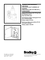
Bradley EFX 60 Thermostatic Mixing Valve
with Optional Cabinet
Model S19-2200 Series
Robinet thermostatique mélangeur EFX 60
avec cabinet facultatif
Bradley modèle S19-2200
Válvula mezcladora termostática EFX 60
con armario opcional
Bradley modelo S19-2200

2 Bradley Corporation • 215-1289 Rev. H; EN 06-9091/29/07
Bradley EFX 60 Thermostatic Mixing Valve with Optional Cabinet
Model S19-2200 Series Installation and Maintenance Instructions
Pre-Installation Information
Overview
Valve: The EFX 60 Thermostatic Mixing Valve (Model S19-2200) is designed for use with drench showers
and/or eye washes. The valve consists of a liquid-filled thermal motor and a piston control mechanism
with positive shut-off of hot when cold water supply is lost to prevent scalding. The valve allows cold
flow in the event of loss or interruption of the hot water supply or failure of the thermostat. The valve may
be mounted in any position.
The maximum inlet temperature of the valve is 180°F (82°C), with a recommended inlet temperature of
120°F–140°F (49°C–60°C). The valve has a maximum operating pressure of 125 PSI (860 kPA).
Cabinet: The optional recess-mounted or surface-mounted cabinet is constructed of 18-gauge stainless
steel with a 16-gauge stainless steel door. The cabinet finish is either stainless steel or baked white enamel.
The optional cabinet window is made of Plexiglass.
Supplies recommended for installation
• lockable shut-off on the outlet if tempered water is supplied to one or more remote showers
• lockable shut-off on the inlets/supplies
• (6) 3/8" wall anchors and fasteners for surface-mounted cabinet
• (4) 1/4" fasteners (and wall anchors, if necessary) for recess-mounted cabinet
• unions on all connections to facilitate removal of valve
Tools required for temperature adjustment
• 5/32" Allen key
• blade screwdriver
Table of Contents
Pre-Installation Information...................................... 2
Valve Installation Instructions................................... 3
Recess-Mounted Cabinet Installation ....................... 4
Surface-Mounted Cabinet Installation...................... 5
Recirculation Instructions ......................................... 6
Maintenance........................................................... 7-8
Troubleshooting..................................................... 8-9
Parts Breakdown and Service Kits.......................... 10
Bradley Warranty Information
Product warranties may be found under “Product Information” on our website at www.bradleycorp.com

Installation Instructions for Valve
CAUTION: If optional cabinet is to be used, the cabinet must be mounted before the valve
is installed. Please refer to the cabinet mounting instructions on pages 4-5.
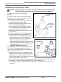
Note: Flush the supply lines before beginning
installation.
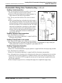
Note: When the check valves are in the open (operating)
position, the cover screw for the stop/check stem will be
flush with the valve cap (see Figure 1).
1. Connect the hot and cold valve supply inlets to the
appropriate hot and cold supply piping.
2. Connect the mixed valve supply outlet from the
valve to the tempered supply piping.
3. Screw the thermometer into the hole in the valve
body (see Figure 2). The thermometer provides a
readout of the outlet water temperature.
4. Pressurize the thermostatic mixing valve and check
for pipe leaks.
5. Slowly open the outlet valve to fill the piping system.
6. Check the temperature when approximately 10
GPM water flow is reached (equivalent to two face
washes) and adjust if necessary [the range of the
valve is 65°F–95°F (18°C–35°C)]. To adjust the
temperature, follow the procedure below:
•remove the slotted cover screw to expose the set screw
•using a 5/32" hex-head Allen key, turn the set screw
counterclockwise to increase the temperature or
clockwise to decrease the temperature.
Note: The standard preset factory temperature setting is
85°F (29°C). Consult proper medical and/or safety
authorities for the optimum temperature recommended for
your particular application.
7. Shut the hot water inlet off by closing either the hot
water check valve or inlet valve. While the hot water
supply is turned off, check to make sure the cold
water is flowing properly. If the cold water is flowing
properly, reopen the hot water supply.
8. Shut the cold water inlet off by closing either the cold water check valve or inlet valve. While the cold
water supply is off, check to make sure that the hot water flow has shut down.
9. Test the system weekly (turn on the water supply and check for constant control of the desired set
temperature).
THERMOMETER
VALVE BODY
Figure 2
VALVE
CAP
Figure 1
STOP/CHECK
COVER SCREW
SLOTTED COVER
SCREW
3Bradley Corporation • 215-1289 Rev. H; EN 06-909 1/29/07
Bradley EFX 60 Thermostatic Mixing Valve with Optional Cabinet
Installation and Maintenance Instructions Model S19-2200 Series

4 Bradley Corporation • 215-1289 Rev. H; EN 06-9091/29/07
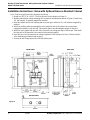
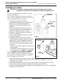
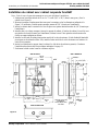
Figure 3
BOTTOM VIEW
SIDE VIEWFRONT VIEW
Installation Instructions: Valve with Optional Recess-Mounted Cabinet
Note: Flush the supply lines before beginning installation.
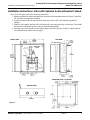
1. Rough in a 24-1/2" W x 28-1/2" H hole in the wall for the cabinet (see Figure 3).
2. Measure and mark the cabinet mounting hole locations at the dimensions shown in Figure 3. Install four
1/4" wall anchors, if required (supplied by installer).
3. Insert the cabinet into the wall opening and secure into place with four 1/4" wall fasteners (supplied by
installer).
4. Install two anchors and screws through the valve bracket in back of the cabinet into a secure brace
(supplied by installer) or into the wall. This must be done to provide adequate support for the valve.
5. Install the valve nipples and one-half of the union ball valve using pipe dope or teflon tape. Then install
the other half of the union ball valve onto the inlet and outlet piping.
6. Insert the valve into the bracket in the cabinet (right side of the valve goes in first). Continue with the
valve installation procedure found on page 3.
7. Position the wall flange tight to the wall and caulk in place.
Bradley EFX 60 Thermostatic Mixing Valve with Optional Cabinet
Model S19-2200 Series Installation and Maintenance Instructions

5Bradley Corporation • 215-1289 Rev. H; EN 06-909 1/29/07
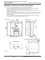
Figure 4
BOTTOM VIEW
Installation Instructions: Valve with Optional Surface-Mounted Cabinet
Note: Flush the supply lines before beginning installation.
1. Measure and mark the cabinet mounting hole locations at the dimensions shown in Figure 4. Install six
3/8" wall anchors (supplied by installer).
2. Position the cabinet onto the wall and secure into place with six 3/8" wall fasteners (supplied by
installer).
3. Install the valve nipples and one-half of the union ball valve using pipe dope or teflon tape. Then install
the other half of the union ball valve onto the inlet and outlet piping.
4. Insert the valve into the bracket in the cabinet (right side of the valve goes in first). Continue with the
valve installation procedure found on page 3.
MOUNTING HOLE LOCATIONS
FRONT VIEW
SIDE VIEW
Bradley EFX 60 Thermostatic Mixing Valve with Optional Cabinet
Installation and Maintenance Instructions Model S19-2200 Series
(57mm)
(64mm)
(64mm)

6 Bradley Corporation • 215-1289 Rev. H; EN 06-9091/29/07
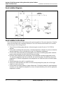
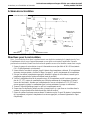
Recirculation Diagram
Recirculation Instructions
Note: Recirculating the water in the system provides constant regulation of the water temperature. Flush the
supply lines thoroughly after completing installation. Close off all fixtures and label them as not available
for use during the recirculating process.
1. Turn off the recirculating pump and turn on the water supply (a water flow rate of 10-15 GPM is
required).
2. Let the water run through the system until a consistent temperature is obtained. If you do not obtain the
required temperature, refer to procedure #6 on page 3 for temperature readjustment.
3. As soon as the water reaches the proper temperature, turn on the recirculating pump (make certain the
proper system temperature has been achieved before proceeding).
4. Check the water temperature at the return pump. If the temperature exceeds the appropriate level by
2°F, adjust the temperature high-limit switch (this will turn off the pump). Wait until the return water
temperature is 5°F below the appropriate level and adjust the low-limit switch (this will turn the pump
back on).
5. Turn the balancing valve until it is completely open.
6. Turn off all fixtures and make sure there is no water running through the system (the cold inlet pipe
should feel warm to the touch).
7. Let the system run for thirty minutes or longer without water. If, after thirty minutes, the water temperature
increases, you may readjust the temperature by slowly closing the balancing valve until the appropriate
temperature is reached.
Bradley EFX 60 Thermostatic Mixing Valve with Optional Cabinet
Model S19-2200 Series Installation and Maintenance Instructions

7Bradley Corporation • 215-1289 Rev. H; EN 06-909 1/29/07
Thermostatic Mixing Valve Maintenance
For maximum efficiency, your thermostatic mixing valve requires a minimum amount of maintenance.
Follow the procedures outlined below to achieve highest performance.
WARNING: To prevent injuries, use proper protective equipment for eyes and skin
when using a propane torch.
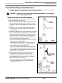
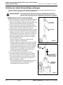
Check the piston for smooth movement
To check the valve's piston for free and smooth movement,
follow the procedures outlined below.
1. Remove the valve's top cap and pull out the push rod and
then the thermostat (see Figure 5). You may use a needle-
nose pliers to remove the thermostat from the valve body if
desired.
2. Insert a 7/16" dia. rod into the valve and into the piston
overheat chamber. Mark the length of the rod inside the
valve (see Figure 6).
3. Push the rod until the piston stops and mark the new length
(the new length should be approximately 1/2" longer than
the original length) (see Figure 6). If the length is not as it
should be, the piston is not moving freely and needs to be
cleaned along with the piston liner. Clean the piston and
liner following the method outlined below:
•remove the control section assembly from the valve body
•remove the top cap and thermostat
•unthread the liner from the cap (it is glued together; the
o-rings must be removed and a propane torch must be
used to melt the glue and loosen the liner)
•any cleaner suitable for brass and stainless steel may be
used (if cleaning with suitable cleaner is not sufficient to
remove debris, a 400-grit sandpaper may be used to polish
and hone the piston and liner).
4. If the piston moves freely, push the mechanism up and
down several times to make sure the piston moves
smoothly and consistently. If movement of the piston is
not consistent, recheck the piston and liner for dirt and
debris as described in procedure #3.
•if the piston parts need to be replaced, contact your
Bradley representative and ask for Piston/Liner Kit
(part number S65-180).
THERMOSTAT
Figure 5
TOP CAP
w/PUSHROD
7/16"
ROD
The second mark
should be 1/2" higher
on the rod than the
first mark.
Figure 6
PISTON
OVERHEAT
CHAMBER
Bradley EFX 60 Thermostatic Mixing Valve with Optional Cabinet
Installation and Maintenance Instructions Model S19-2200 Series

8 Bradley Corporation • 215-1289 Rev. H; EN 06-9091/29/07
Thermostatic Mixing Valve Maintenance continued . . .
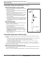
Check the thermostat for proper operation
To check the valve's thermostat for proper operation, follow the
procedures outlined below.
1. Remove the top cap and pull out the push rod and thermostat
(see Figure 5 on page 7).
2. Insert a 7/16" dia. rod into the thermostat bellows. Mark the
length of the rod inside the bellows (see Figure 7).
3. Mark the length of the thermostat bellows (at room temperature,
with 10 lb. of force, the bellows length should be approx.
2-2/3") (see Figure 7).
4. If the thermostat bellows length is not in the proper range, the
thermostat must be replaced (it cannot be repaired). Contact
your Bradley representative and ask for Thermostat Kit (part
number S65-178).
Adjust the temperature
To adjust the valve's temperature to other than the factory preset,
follow the procedures outlined below.
1. Turn on the water and let it run until at least 10 GPM is
flowing through the valve.
2. Remove the slotted cover screw to expose the set screw.
3. Using a 5/32" hex-head Allen key, turn the set screw
counterclockwise to increase the temperature or clockwise
to decrease the temperature.
4. When the adjustment is complete, replace the cover screw
and turn off the water.
Thermostatic Mixing Valve Troubleshooting
Note: Before attempting to troubleshoot the valve or disassemble the components, check for the following
conditions:
• make sure that the check valves are fully open (the slotted stem must be flush with the stop/check cap)
(see Figure 1 on page 3) and that all inlet and outlet shut-off valves are open
• make sure that the hot and cold inlet pipes are connected properly, and that there are no cross-
connections or leaking stop/check valves
• check the hot water heater output to make sure that it is at least 15° F above the set temperature.
Be sure to close the appropriate shut-off valves prior to disassembly of the valve and reopen the valves
after inspection and repair is complete.
Problem: No hot water flow (cold water flow only)
Cause: The thermostat has failed and, subsequently, the safety shut-off has engaged (the shut-off valve has
closed on either the inlets or outlet).
Solution: See “Check the thermostat for proper operation” above and follow the step-by-step procedure.
7/16"
ROD
Bellows length
should be 2-1/2"
to 2-3/4"
Figure 7
THERMOSTAT
Bradley EFX 60 Thermostatic Mixing Valve with Optional Cabinet
Model S19-2200 Series Installation and Maintenance Instructions

9Bradley Corporation • 215-1289 Rev. H; EN 06-909 1/29/07
Thermostatic Mixing Valve Troubleshooting continued . . .
Problem: Limited water flow
Cause: The inlet shut-off valve may be partially closed or there
has been a significant decrease in water pressure.
Solution: See “Check the thermostat for proper operation” on
page 8 and follow the step-by-step procedure.
Cause: The stop and check sections of the valve do not move
freely.
Solution: Dirt and debris have collected on the check screen or
seat, limiting the movement of the stop and checks. Remove
the stop and checks, clean the screen and seat and reassemble
the valve (see Figure 8). Do not remove the seat. The compo-
nents may be scraped with a screwdriver to remove debris.
A pair of tweezers works well for pulling debris out from
the seat. If the stop and checks need to be replaced, contact
your Bradley representative and ask for Check/Stop Kit
(part number S65-179).
Problem: Improper water temperature
Cause: Recirculation is not balanced.
Solution: See “Recirculation instructions” on page 6 and follow
the step-by-step procedure.
Problem: External leaks in the system
Cause: Either the NPT joints or the o-rings have been damaged.
Solution: Replace the NPT joints and/or o-rings where necessary. For replacement of o-rings, contact your
Bradley representative and ask for O-Ring/Seal Kit (part number S65-177).
Problem: Temperature fluctuation
Cause: Thermostat is slowly failing.
Solution: See “Check the thermostat for proper operation” on page 8 and follow the step-by-step procedure.
Cause: Recirculation is not balanced.
Solution: See “Recirculation instructions” on page 6 and follow the step-by-step procedure.
Cause: Inlet supply line to the mixing valve is being shared by other pieces of equipment that are used only
periodically, such as laundry appliances or washdown stations. It may reduce the inlet pressure to the
mixing valve to less than 10 PSI. The supply line size may not be large enough to supply both the valve
and the other appliances.
Solution: Enlarge the supply line size, reconfigure the supply line or regulate the supply usage.
STOP AND
CHECKS
Figure 8
VALVE
SEAT
VALVE
SCREEN
Bradley EFX 60 Thermostatic Mixing Valve with Optional Cabinet
Installation and Maintenance Instructions Model S19-2200 Series

10 Bradley Corporation • 215-1289 Rev. H; EN 06-9091/29/07
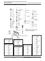
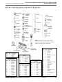
EFX 60: Parts Breakdown and Service Kits
Thermostat Kit S65-178
Item Qty. Description
15 1 Thermostat
17 1 O-Ring
21 1 O-Ring
Check/Stop Kit S65-179
Item Qty. Description
25 2 Cap
26 2 O-Ring
27 2 Stem
28 2 O-Ring
29 2 Strainer
30 2 Spring
31 2 Holder (for Seal)
32 2 Seal
33 2 Washer
34 2 Nut
35 2 Seat
36 2 O-Ring
O-Ring Kit S65-177
Item Qty. Description
2 1 O-Ring
10 1 O-Ring
12 1 O-Ring
17 1 O-Ring
18 1 O-Ring
19 1 O-Ring
21 1 O-Ring
26 2 O-Ring
28 2 O-Ring
36 2 O-Ring
Piston & Liner Kit S65-180
Item Qty. Description
2 1 O-Ring
3 1 Liner
4 1 Washer
5 1 Screw
6 1 Spring
7 1 Lower Overheat
Chamber
8 1 Spring
9 1 Washer
10 1 O-Ring
11 1 Piston
13 1 Upper Overheat
Chamber
45 1 Washer
Bradley EFX 60 Thermostatic Mixing Valve with Optional Cabinet
Model S19-2200 Series Installation and Maintenance Instructions
Center Section Kit S65-305
Item Qty. Description
2 1 O-Ring
3 1 Liner
4 1 Washer
5 1 Screw
6 1 Spring
7 1 Lower Overheat
Chamber
8 1 Spring
9 1 Washer
10 1 O-Ring
11 1 Piston
12 1 O-Ring
13 1 Upper Overheat
Chamber
14 1 Upper Seat
15 1 Thermostat
16 1 Pushrod
17 1 O-Ring
18 1 O-Ring
19 1 O-Ring
20 1 Mixing Valve Cap
21 1 O-Ring
22 1 Control Cap
23 1 Set Screw
24 1 Screw
45 1 Washer
NOTE: Kit numbers for rough brass finish
and standard range thermostat. Contact
Bradley for other configurations.
Washer/Seal Kit S65-311
Item Qty. Description
4 1 Washer
9 1 Washer
32 2 Seal
33 2 Washer
45 1 Washer

11Bradley Corporation • 215-1289 Rev. H; EN 06-909 1/29/07
Information avant l'installation
Description
Robinet : Le robinet thermostatique mélangeur EFX 60, (modèle S19-2200), est conçu pour être utilisé
avec les douches d'urgence et/ou les douches oculaires. Le robinet est constitué d'un moteur thermique
rempli de liquide. Pour empêcher les échaudages, un mécanisme de contrôle à piston ferme
automatiquement l'alimentation en eau chaude en cas de manque d'eau froide. Le robinet distribue un jet
d'eau froide, en cas de perte ou d'interruption d'alimentation en eau chaude, ou en cas d'une panne du
thermostat. Le robinet peut être installé dans n'importe quelle position.
La température maximum à l'entrée du robinet est de 82°C (180°F), et la température recommandée à l'entrée
est de 49° à 60°C (120° à 140°F). La pression d'opération maximum du robinet est de 860 kPA (125 psi).
Cabinet : Le module, à montage suspendu ou de surface, est construit en acier inoxydable de calibre 18,
avec une porte en acier inoxydable de calibre 16. La finition du cabinet est en acier inoxydable ou en
émail cuit de couleur blanc. La fenêtre en Plexiglas est facultative.
Fournitures recommandées pour l'installation
•arrêt d'alimentation avec verrouillage aux sorties, si certaines douches du site sont alimentées en
eau tempérée
•arrêt d'alimentation avec verrouillage aux entrées
•6 ancrages muraux et attaches de 3/8" pour le cabinet de surface
•4 attaches (et ancrages muraux si nécessaire) de 1/4" pour le cabinet suspendu
•raccords à tous les branchements, pour faciliter l'enlèvement du robinet
Outils nécessaires pour l'ajustement de la température
•clé Allen de 5/32"
•tournevis plat
Informations de garantie Bradley
Les garanties du produit figurent sous la rubrique « Informations techniques » sur notre site Internet
à www.bradleycorp.com.
Table des matières
Information avant l'installation ............................... 11
Installation du robinet ............................................. 12
Installation du cabinet suspendu............................. 13
Installation du cabinet de surface............................ 14
Directives pour la recirculation............................... 15
Entretien............................................................. 16-17
Dépannage ......................................................... 17-18
Liste des pièces et des trousses de service.............. 19
R
obinet thermostatique mélangeur EFX 60, avec cabinet facultatif
Instructions pour l’installation et l’entretien Bradley modèle
S19-2200

12 Bradley Corporation • 215-1289 Rev. H; EN 06-9091/29/07
Robinet thermostatique mélangeur EFX 60, avec cabinet facultatif
Bradley modèle S19-2200 Instructions pour l’installation et l’entretien
Installation du robinet
ATTENTION : Si on utilise le cabinet facultatif, il devra être installé avant le robinet.
Se référer aux directives pour l'installation du cabinet, aux pages 13 et 14.
Note : Vider le tuyau d'approvisionnement en eau avant
de débuter l'installation.
Note : Lorsque les clapets anti-retour sont en position
ouverts, la vis du chapeau de la tige d'arrêt est de niveau
avec le capuchon de robinet (voir Figure 1).
1. Brancher l'eau chaude et froide d'entrée
d'alimentation du robinet à la tuyauterie appropriée.
2. Brancher la sortie d'alimentation du robinet
mélangeur à la tuyauterie d'alimentation en eau
tempérée.
3. Visser le thermomètre dans l'orifice du corps du
robinet (voir Figure 2). Le thermomètre donne une
lecture de la température de l'eau à la sortie.
4. Pressuriser le robinet thermostatique mélangeur et
vérifier s'il y a des fuites.
5. Ouvrir le robinet doucement, de manière à remplir
le système de tuyauterie.
6. Lorsque qu'un débit moyen de 38 litres/minute
(10 gallons/minute) est atteint (équivaut à un double
rinçage facial), vérifier la température et ajuster si
nécessaire [la variation du robinet est de 18° à 35°C
(65° à 95°F)]. Pour ajuster la température, procéder
comme suit :
•enlever la vis encochée du chapeau, afin d'exposer la
vis d'ajustement
•à l'aide d'une clé Allen hexagonale de 5/32", tourner
la vis d'ajustement vers la gauche pour augmenter
la température ou vers la droite pour l'abaisser.
Note : La température préréglée en usine est de 29°C
(85°F). Consulter les autorités, médicales ou de sécurité,
pour déterminer la température maximale recommandée
pour votre application en particulier.
7. Fermer l'alimentation en eau chaude, soit par le clapet anti-retour ou l'entrée d'eau chaude. Alors que
l'alimentation en eau chaude est fermée, vérifier si le jet d'eau froide est régulier. Si oui, ouvrir
l'alimentation en eau chaude.
8. Fermer l'alimentation en eau froide, soit par le clapet anti-retour ou l'entrée d'eau froide. Alors que
l'alimentation en eau froide est fermée, s'assurer que le jet d'eau chaud s'est arrêté.
9. Faire une vérification hebdomadaire du système (ouvrir l'alimentation en eau et vérifier si la température
réglée pour l'eau est constante).
THERMOMÈTRE
Figure 2
Figure 1
VIS DU CHAPEAU
DE LA TIGE
D'ARRÊT
CAPUCHON
DE ROBINET
VIS ENCOCHÉE
DU CHAPEAU
CORPS DE
ROBINET

13Bradley Corporation • 215-1289 Rev. H; EN 06-909 1/29/07
Figure 3
VUE DU DESSOUS
VUE LATERALEVUE DE FACE
Installation du robinet avec cabinet suspendu facultatif
Note : Vider le tuyau d'approvisionnement en eau avant de débuter l'installation.
1. Pratiquer une ouverture initiale de 62 cm L x 72 cm H (24,5" x 28,5") dans le mur, pour y fixer le
cabinet (voir Figure 3).
2. Mesurer et marquer l'emplacement des trous pour le montage, selon les dimensions indiquées à la
Figure 3. Si nécessaire, installer quatre ancrages muraux de 1/4" (fournis par l'installateur).
3. Insérer le cabinet dans l'ouverture et le fixer en place avec quatre attaches murales de 1/4" (fournies par
l'installateur).
4. Installer deux vis et deux ancrages à travers le support de robinet, à l'arrière du cabinet, le tout fixé avec
une attache de sécurité (fournie par l'installateur) ou dans le mur. Cette opération est nécessaire afin
d'offrir un support adéquat au robinet.
5. Installer les raccords du robinet ainsi qu'une moitié de la valve de retenue, à l'aide d'enduit d'étanchéité
pour tuyaux ou de ruban de téflon. Puis, installer l'autre moitié de la valve de retenue sur l'entrée et la
sortie de la tuyauterie.
6. Insérer le robinet dans le support, dans le cabinet (le côté droite du robinet en premier). Continuer
l'installation du robinet selon les procédures indiquées à la page 12.
7. Positionner la bride contre le mur et calfeutrer en place.
578 mm
(22,75")
PORTE
679 mm
(26,75")
PORTE
BRIDE
ENTREES :
1" NPT
TROUS DE 7 mm (0,28")
DE DIAMÈTRE,
4 POUR CHAQUE COTE,
8 AU TOTAL
VALVE DE
RETENUE
RACCORDS
DU
ROBINET
SORTIE :
1,25" NPT
R
obinet thermostatique mélangeur EFX 60, avec cabinet facultatif
Instructions pour l’installation et l’entretien Bradley modèle
S19-2200
259 mm
(10,19")
762 mm
(30")
194 mm
(7,63")
222 mm
(8,75")
660 mm
(26")
610 mm
(24")
51 mm (2")
57 mm (2,25")
64 mm
(2,5")
127 mm
(5")
711 mm
(28")
457 mm
(18")
64 mm
(2,5")
165 mm
(6,5")
51 mm
(2")

14 Bradley Corporation • 215-1289 Rev. H; EN 06-9091/29/07
Figure 4
VUE DU DESSOUS
Installation du robinet avec cabinet de surface facultatif
Note : Vider le tuyau d'approvisionnement en eau avant de débuter l'installation.
1. Mesurer et marquer l'emplacement des trous pour le montage, selon les dimensions indiquées à la
Figure 4. Installer six ancrages muraux de 3/8" (fournis par l'installateur).
2. Aligner le cabinet face aux trous de montage et le fixer en place avec six attaches murales de 3/8"
(fournies par l'installateur).
3. Installer les raccords du robinet ainsi qu'une moitié de la valve de retenue, à l'aide d'enduit d'étanchéité
pour tuyaux ou de ruban de téflon. Puis, installer l'autre moitié de la valve de retenue sur l'entrée et la
sortie de la tuyauterie.
4. Insérer le robinet dans le support, dans le cabinet (le côté droite du robinet en premier). Continuer
l'installation du robinet selon les procédures indiquées à la page 12.
VUE DE FACE
VUE LATERALE
578 mm
(22,75")
PORTE
679 mm
(26,75")
PORTE
SORTIE : 1,25" NPT
ENTREES :
1" NPT
POSITION DES TROUS POUR L'INSTALLATION
RACCORDS
DU
ROBINET
VALVE DE
RETENUE
TROUS DE 12 mm
(0,47") DE DIAMÈTRE,
EN 6 ENDROITS
Robinet thermostatique mélangeur EFX 60, avec cabinet facultatif
Bradley modèle S19-2200 Instructions pour l’installation et l’entretien
259 mm
(10,19")
222 mm
(8,75")
194 mm
(7,63")
64 mm
(2,5")
711 mm
(28")
165 mm
(6,5")
64 mm
(2,5")
57 mm
(2,25")
130 mm
(5,13")
248 mm
(9,75")
610 mm
(24")
233 mm
(9,19")
51 mm
(2")
51 mm
(2")
508 mm
(20")
610 mm
(24")

15Bradley Corporation • 215-1289 Rev. H; EN 06-909 1/29/07
Schéma de recirculation
Directives pour la recirculation
Note : La recirculation d'eau dans le système fournie une régulation constante de la température de l'eau.
Complètement vider le tuyau d'approvisionnement en eau après avoir terminé l'installation. Durant le
processus de recirculation, fermer tous les douches de premier secours et les identifier comme étant occupés.
1. Fermer la pompe de recirculation et ouvrir l'alimentation en eau [un débit de 38 à 56 litres/minute
(10 à 15 gallons/minute) est nécessaire].
2. Laisser circuler l'eau dans le système, jusqu'à l'atteinte d'une température cohérente. Si la température
nécessaire n'est pas atteinte, se référer à l'étape 6 en page 12, pour le réajustement de la température.
3. Dès que l'eau atteint la température appropriée, démarrer la pompe de recirculation (s'assurer que la
température appropriée du système est atteinte avant de procéder).
4. Vérifier la température d'eau de la pompe de retour. Si la température excède le niveau approprié par
plus de 1°C (2°F), ajuster le commutateur pour l'élévation maximum de la température (la pompe
cessera de fonctionner). Attendre que la température de l'eau se soit abaissée à 2,8°C (5°F) sous le
niveau approprié et ajuster le commutateur pour le niveau minimum (la pompe va redémarrer).
5. Tourner le clapet d'équilibrage jusqu'à ce qu'il soit complètement ouvert.
6. Fermer tous les douches de premier secours et s'assurer qu'il n'y a pas d'eau en circulation dans le
système (le tuyau d'entrée d'eau froide devrait être tiède au toucher).
7. Laisser le système fonctionner sans eau durant 30 minutes ou plus. Si après 30 minutes, la température
de l'eau augmente, réajuster la température à son niveau approprié, en fermant légèrement le clapet
d'équilibrage.
CLAPET ANTI-RETOUR (TYPICAL)
EAU
FROIDE
COLLECTEUR
DE CHALEUR,
CHUTE 71 cm
(28")
CHAUFFE-EAU
RESERVOIR DE STOCKAGE
COMMUTATEUR DE
TEMPERATURE
RECIRCULATION
ALTERNATIVE
[plus de
19 litres/minute
(5 gal/min)]
DÉBIT D’EAU
TEMPÉRÉE
CLAPET
D'EQUILIBRAGE
(TYPICAL)
POMPE DE
RECIRCULATION
FROIDE
CHAUDE
DÉBIT DE
RETOUR
EAU TEMPÉRÉE
RECIRCULÉE
R
obinet thermostatique mélangeur EFX 60, avec cabinet facultatif
Instructions pour l’installation et l’entretien Bradley modèle
S19-2200

16 Bradley Corporation • 215-1289 Rev. H; EN 06-9091/29/07
Entretien du robinet thermostatique mélangeur
Pour une efficacité maximum, le robinet thermostatique mélangeur nécessite peu d'entretien. Suivre les
directives ci-dessous pour obtenir les meilleures performances.
AVERTISSEMENT : Pour empêcher les blessures, porter les équipements protecteurs
pour les yeux et la peau, lors de l'utilisation d'une torche au propane.
Vérifier l'aisance de la course du piston
Pour vérifier l'aisance de la course du piston, procéder comme suit.
1. Enlever le capuchon du robinet et sortir la bielle, puis le
thermostat (voir Figure 5). Si désiré, utiliser une pince à bec
effilé pour enlever le thermostat du corps du robinet.
2. Insérer une bielle de 11 mm (0,44") de diamètre dans le
robinet et dans la chambre de surchauffe du piston. Noter la
longueur de la bielle dans le robinet (voir Figure 6).
3. Pousser la bielle, jusqu'à l'arrêt du piston et noter la nouvelle
longueur [la nouvelle longueur devrait être plus longue que
l'originale, environ 13 mm (0,5") de plus (voir Figure 6)].
Si la longueur n'est pas ce qu'elle devrait être, la course du
piston ne se fait pas librement. Le piston et sa chemise
nécessite un nettoyage. Nettoyer le piston et sa chemise
selon la méthode suivante :
•enlever la section de contrôle du corps du robinet
•enlever le capuchon et le thermostat
•séparer la chemise et le capuchon (ils sont collés ensemble ;
les bagues doivent être enlevées et une torche au propane
doit être utilisée pour fondre la colle et libérer la chemise)
•tout nettoyeur convenant au laiton et à l'acier inoxydable,
peut être utilisé (si le nettoyage ne suffit pas à enlever
les débris, un papier sablé 400 peut être utilisé pour
polir et affiler le piston et sa chemise).
4. Si la course du piston se fait librement, pousser le
mécanisme de haut en bas plusieurs fois, pour s'assurer
que la course du piston se fait constamment en douceur.
Si la course du piston ne se fait pas en douceur, vérifier à
nouveau le piston et sa chemise pour les saletés et les
débris, tel qu'indiqué à l'étape 3.
•si des pièces du piston doivent être remplacées, contacter
votre représentant Bradley et demander la trousse
Piston/Chemise (pièce numéro S65-180).
THERMOSTAT
Figure 5
CAPUCHON
AVEC BIELLE
BIELLE
DE 11 mm
(0,44")
Figure 6
La seconde marque sur
la bielle devrait être
située 13 mm (0,5") plus
haute que la première.
CHAMBRE DE
SURCHAUFFE
DU PISTON
Robinet thermostatique mélangeur EFX 60, avec cabinet facultatif
Bradley modèle S19-2200 Instructions pour l’installation et l’entretien

17Bradley Corporation • 215-1289 Rev. H; EN 06-909 1/29/07
Entretien du robinet thermostatique mélangeur, suite
Vérification du fonctionnement approprié du thermostat
Pour vérifier si le thermostat du robinet a un fonctionnement
approprié, procéder comme suit.
1. Enlever le chapeau, puis sortir la bielle et le thermostat (voir
Figure 5, page 16).
2. Insérer une bielle de 11 mm (0,44") de diamètre dans le
soufflet du thermostat. Noter la longueur de la bielle dans le
soufflet (voir Figure 7).
3. Noter la longueur du soufflet du thermostat [à température de
la pièce, avec 4,45 kg / 44,5 N (10 lb) de force, la longueur du
soufflet devrait être d'environ 67 mm (2,67")] (voir Figure 7).
4. Si la longueur du soufflet du thermostat n'est pas appropriée,
le thermostat doit être remplacé (il ne peut être réparé).
Contacter votre représentant Bradley et demander la trousse
Thermostat (pièce numéro S65-178).
Ajuster la température
Pour ajuster la température du robinet à un niveau différent de
celui réglé en usine, procéder comme suit.
1. Ouvrir et laisser couler l'eau, jusqu'à ce qu'un débit de
38 litres/minute (10 gallons/minute) s'écoule par le robinet.
2. Eenlever la vis encochée du chapeau, afin d'exposer la vis
d'ajustement.
3. À l'aide d'une clé Allen hexagonale de 5/32", tourner la vis
d'ajustement vers la gauche pour augmenter la température
ou vers la droite pour l'abaisser.
4. Lorsque l'ajustement est complété, remettre la vis du chapeau et fermer l'eau.
Dépannage du robinet thermostatique mélangeur
Note : Avant de tenter un dépannage du robinet ou de démonter les composantes, vérifier les points suivants :
• s'assurer que les clapets anti-retour sont complètement ouverts (la tige encochée doit être de niveau
avec le capuchon de la tige d'arrêt) (voir Figure 1 à la page 12) et s'assurer également que tous les
robinets d'entrées et de sorties sont ouverts
• s'assurer que les tuyaux d'entrée pour l'eau chaude et l'eau froide sont correctement branchés et qu'il
n'y a aucun branchement croisé ou fuites aux robinets arrêt/contrôle
• vérifier la sortie du chauffe-eau pour s'assurer que la température est à au moins 8,3°C (15°F)
au-dessus du niveau réglé.
S'assurer de fermer les robinets d'arrêt appropriés, avant de démonter le robinet. Les rouvrir quand
l'inspection et la réparation sont complétées.
Problème : Aucun débit d'eau chaude (débit d'eau froide seulement)
Cause : Le thermostat est en panne, donc le robinet d'arrêt de secours s'est embrayé (le robinet d'arrêt a
fermé soit les entrées ou soit les sorties).
Solution : Voir la section « Vérification du fonctionnement approprié du thermostat » ci-dessus et suivre
les procédures qui y sont décrites.
La longueur du
soufflet devrait être
de 63 à 70 mm
(2,5" à 2,75")
Figure 7
THERMOSTAT
BIELLE
DE 11 mm
(0,44")
R
obinet thermostatique mélangeur EFX 60, avec cabinet facultatif
Instructions pour l’installation et l’entretien Bradley modèle
S19-2200

18 Bradley Corporation • 215-1289 Rev. H; EN 06-9091/29/07
Dépannage du robinet thermostatique mélangeur, suite
Problème : Débit d'eau limité
Cause : Le robinet d'arrêt d'entrée peut être partiellement fermé,
ou il y a eu une baisse significative de la pression d'eau.
Solution : Voir la section « Vérification du fonctionnement
approprié du thermostat » à la page 17 et suivre les
procédures qui y sont décrites.
Cause : Les sections arrêt/contrôle du robinet ne bougent pas
librement.
Solution : Des saletés et des débris se sont amassés sur le crible
ou le siège, limitant ainsi les mouvements des arrêts/contrôles.
Enlever l'arrêt/contrôle, nettoyer le crible et le siège, puis
assembler le robinet (voir Figure 8). Ne pas enlever le siège.
Les composantes peuvent être grattées avec un tournevis,
pour en enlever les débris. Les débris dans le siège s'enlèvent
bien avec une paire de pinces. Si l'arrêt/contrôle doit être
remplacé, contacter votre représentant Bradley et demander
la trousse Arrêt/Contrôle (pièce numéro S65-179).
Problème : Température d'eau irrégulière
Cause : Mauvais ajustement de la recirculation.
Solution : Voir les « Directives pour la recirculation » à la page
15 et suivre les procédures indiquées.
Problème : Fuites à l'extérieur du système
Cause : L'un des joints NPT ou les bagues sont endommagés.
Solution : Remplacer les joints NPT et/ou les bagues si nécessaire. Pour le remplacement des bagues,
contacter votre représentant Bradley et demander la trousse Bagues/Joints (pièce numéro S65-177).
Problème : Variation de la température
Cause : Le thermostat sera bientôt en panne.
Solution : Voir la section « Vérification du fonctionnement approprié du thermostat » à la page 17 et
suivre les procédures décrites.
Cause : Mauvais ajustement de la recirculation.
Solution : Voir les « Directives pour la recirculation » à la page 15 et suivre les procédures indiquées.
Cause : L'entrée d'alimentation du robinet mélangeur est partagée avec d'autres pièces d'équipement qui ne
sont utilisées que périodiquement, tels appareils de blanchisserie ou stations de lavage. Cela peut
réduire la pression d'entrée du robinet mélangeur à moins de 69 kPA (10 psi). La grosseur de la
canalisation d'alimentation ne suffit peut-être pas à fournir le robinet et les autres équipements.
Solution : Installer une canalisation d'alimentation plus grosse, modifier la canalisation d'alimentation ou
régulariser l'utilisation de l'alimentation.
Figure 8
SECTIONS
ARRÊT/CONTRÔLE
CRIBLE DE
ROBINET
SIEGE DE
ROBINET
Robinet thermostatique mélangeur EFX 60, avec cabinet facultatif
Bradley modèle S19-2200 Instructions pour l’installation et l’entretien

19Bradley Corporation • 215-1289 Rev. H; EN 06-909 1/29/07
R
obinet thermostatique mélangeur EFX 60, avec cabinet facultatif
Instructions pour l’installation et l’entretien Bradley modèle
S19-2200
Trousse Thermostat S65-178
Pièce Qté. Description
15 1 Thermostat
17 1 Bague
21 1 Bague
25 - Capuchon
26 - Bague
15 - Thermostat
16 - Bielle
24 - Vis
23 - Vis d'ajustement
22 - Capuchon
de contrôle
20 - Capuchon
de robinet
mélangeur
11 - Piston
10 - Bague
28 - Bague
36 - Bague
2 - Bague
27 - Tige
29 - Filtre
30 - Ressort
6 - Ressort
8 - Ressort
7 - Chambre de
surchauffe inférieure
5 - Vis
3 - Chemise
32 - Joint
33 - Rondelle
45 - Rondelle
4 - Rondelle
9 - Rondelle
34 - Écrou
35 - Siège
31 - Support
de joint
17 - Bague
21 - Bague
19 - Bague
12 - Bague
14 - Siège
supérieur
18 - Bague
38 - Tuyau en laiton
[19 mm (3/4") IPS]
37
Plaque signalétique
1
Corps du robinet
43
Thermomètre
EFX 60 : Liste des pièces et trousses de service
13 - Chambre de
surchauffe
supérieure
Trousse Piston/
Chemise S65-180
Pièce Qté. Description
2 1 Bague
3 1 Chemise
4 1 Rondelle
51Vis
6 1 Ressort
7 1 Chambre de
surchauffe
inférieure
8 1 Ressort
9 1 Rondelle
10 1 Bague
11 1 Piston
13 1 Chambre de
surchauffe
supérieure
45 1 Rondelle
Trousse Bague S65-177
Pièce Qté. Description
2 1 Bague
10 1 Bague
12 1 Bague
17 1 Bague
18 1 Bague
19 1 Bague
21 1 Bague
26 2 Bague
28 2 Bague
36 2 Bague
Trousse Arrêt/Contrôle
S65-179
Pièce Qté. Description
25 2 Capuchon
26 2 Bague
27 2 Tige
28 2 Bague
29 2 Filtre
30 2 Ressort
31 2 Support de
joint
32 2 Joint
33 2 Rondelle
34 2 Écrou
35 2 Siège
36 2 Bague
Trousse Portion Centrale S65-305
Pièce Qté. Description
2 1 Bague
3 1 Chemise
4 1 Rondelle
51Vis
6 1 Ressort
7 1 Chambre de surchauffe
inférieure
8 1 Ressort
9 1 Rondelle
10 1 Bague
11 1 Piston
12 1 Bague
13 1 Chambre de surchauffe
supérieure
14 1 Siège supérieur
15 1 Thermostat
16 1 Bielle
17 1 Bague
18 1 Bague
19 1 Bague
20 1 Capuchon de robinet
mélangeur
21 1 Bague
22 1 Capuchon de contrôle
23 1 Vis d'ajustement
24 1 Vis
45 1 Rondelle
NOTE : Numéros de trousse pour la finition
laiton brut et le thermostat standard. Contacter
Bradley pour toute autre configuration.
Trousse Rondelle/Joint
S65-311
Pièce Qté. Description
4 1 Rondelle
9 1 Rondelle
32 2 Joint
33 2 Rondelle
45 1 Rondelle

20 Bradley Corporation • 215-1289 Rev. H; EN 06-9091/29/07
Información previa a la instalación
Generalidades
Válvula: La válvula mezcladora termostática EFX 60 (modelo S19-2200) está diseñada para ser usada con
duchas de emergencia y/o lavadores de ojos. La válvula consta de un motor térmico llenado de líquido.
Para prevenir quemaduras, un mecanismo de control por pistón cierra automáticamente el suministro de
agua caliente, en caso de falta de suministro de agua fría. La válvula permite el flujo de agua fría en caso
de pérdida o interrupción del suministro de agua caliente o falla del termostato. La válvula se puede
montar en cualquier posición.
La temperatura de entrada máxima de la válvula es de 82°C (180°F); se recomienda una temperatura de
entrada de 49° a 60°C (120° a 140°F). La válvula tiene una presión de operación máxima de 860 kPA
(125 psi).
Armario: El armario opcional para montar sobre la superficie o empotrado está construido de acero
inoxidable de calibre 18 con una puerta de acero inoxidable de calibre 16. El acabado del armario puede ser
de acero inoxidable o de esmalte al horno de color blanco. La ventana opcional del armario es de Plexiglás.
Materiales requeridos para la instalación
•cierre inmovilizable en la salida si se suministra agua tibia para una o más duchas localizadas a
distancia
•cierre inmovilizable en las entradas/suministros
•(6) pernos de anclaje de 3/8 de pulg. y pernos para el armario de montar en superficie
•(4) pernos de 1/4 de pulg. (y pernos de anclaje, en caso de que sean necesarios) para los armarios
empotrados
•uniones en todas las conexiones para facilitar el desmontaje de la válvula
Herramientas requeridas para ajustar la temperatura
•llave Allen de 5/32 de pulg.
•destornillador de punta plana
Información de la garantía de Bradley
Las garantías del producto se pueden encontrar en “Información del producto” o en nuestro sitio
Web www
.bradleycorp.com.
Contenido
Información previa a la instalación......................... 20
Instalación de la válvula.......................................... 21
Instalación del armario empotrado.......................... 22
Instalación del armario para montar en superficies... 23
Instrucciones de recirculación................................. 24
Mantenimiento................................................... 25-26
Resolución de problemas................................... 26-27
Lista de piezas y juegos para reparación ................ 28
Válvula mezcladora termostática EFX 60 con armario opcional
Bradley modelo S19-2200 Instrucciones para la instalación y mantenimiento
La page est en cours de chargement...
La page est en cours de chargement...
La page est en cours de chargement...
La page est en cours de chargement...
La page est en cours de chargement...
La page est en cours de chargement...
La page est en cours de chargement...
La page est en cours de chargement...
-
 1
1
-
 2
2
-
 3
3
-
 4
4
-
 5
5
-
 6
6
-
 7
7
-
 8
8
-
 9
9
-
 10
10
-
 11
11
-
 12
12
-
 13
13
-
 14
14
-
 15
15
-
 16
16
-
 17
17
-
 18
18
-
 19
19
-
 20
20
-
 21
21
-
 22
22
-
 23
23
-
 24
24
-
 25
25
-
 26
26
-
 27
27
-
 28
28


Bradley EFX 60 S19-2200 Series Installation And Maintenance Instructions Manual
- Taper
- Installation And Maintenance Instructions Manual
dans d''autres langues
- English: Bradley EFX 60 S19-2200 Series
- español: Bradley EFX 60 S19-2200 Series
Documents connexes
-
Bradley EFX60P Installation Instructions Manual
-
-
-
Bradley Corporation S19-2300 Guide d'installation
-
Bradley Smoker Terreon WF3208 Manuel utilisateur
-
-
-