
Installation
Installation
Instalación
TDB3108
Terreon
®
54" Circular Deep Bowl Washfountain with
Infrared Control
Terreon
®
Lavabo fontaine 1372 mm (54") à cuvette
profonde circulaire avec commande à infrarouge
Fuente de lavado circular con palangana profunda
Terreon
®
de 1372 mm (54") con control infrarrojo
WF3208
Terreon
®
Extra Height 54" Circular Classic
Washfountain with 9" Deep Bowl and Infrared Control
Terreon
®
Lavabo fontaine 1372 mm (54") à hauteur
supplémentaire classique circulaire à cuvette
profonde de 229 mm (9") et commande à infrarouge
Fuente de lavado clásica circular Terreon
®
de altura
adicional de 1372 m (54") con palangana profunda de
229 mm (9") y control infrarrojo
P.O. Box 309, Menomonee Falls, WI 53052-0309
Phone: 1-800-BRADLEY Fax: (262) 251-5817
http:\\www.bradleycorp.com
215-1187 Rev N; EN 06-915B
© 2007 Bradley Corporation
Page 1 of 85 4/6/2007
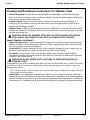
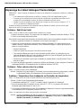
IMPORTANT!
Read this entire installation manual to ensure
proper installation. When finished with the
installation, file this manual with the owner
or maintenance department.
Separate parts from packaging and make
sure all parts are accounted for before
discarding any packaging material. If any
parts are missing, do not begin installation
until you obtain the missing parts.
Make sure that all water supply lines have
been flushed and then completely turned off
before beginning installation. Debris in
supply lines can cause valves to
malfunction.
Hardware supplied by installer must be
appropriate for wall construction. Wall
anchors used must have a minimum pull-out
rating of 1,000 lbs.
The Adaptive® Infrared control must be
connected with a 24 VAC Class II
transformer. Connections to 110 VAC can
cause personal injury and will result in
damage to the electronics.
Product warranties may be found under
“Product Information” on our web site at
www.bradleycorp.com.
IMPORTANT !
Lire ce manuel d’installation dans son
intégralité pour garantir une installation
appropriée. Une fois celle-ci terminée,
classer ce manuel auprès du service à la
clientèle ou d’entretien.
Séparer les pièces de l’emballage et veiller à
bien avoir toutes les pièces avant de jeter le
matériau d’emballage. Le cas échéant, ne
pas commencer l’installation avant d’avoir
obtenu les pièces manquantes.
Veiller à bien vidanger et fermer toutes les
conduites d’eau avant de commencer
l’installation. Tout débris dans les conduites
d’alimentation risque de provoquer un
mauvais fonctionnement des soupapes.
La quincaillerie fournie par l’installateur doit
être appropriée pour la construction des
murs. Les dispositifs d’ancrage muraux
doivent avoir un indice d’arrachement
minimum de 454 kg (1 000 lbs.).
La commande à infrarouge Adaptive® doit
être connectée avec un transformateur
24 V c.a. Classe II. Des connexions à du
110 V c.a. peuvent provoquer des blessures
personnelles et endommager les
composants électroniques.
Les garanties du produit figurent sous la
rubrique « Informations techniques » sur
notre site Internet à www.bradleycorp.com.
¡IMPORTANTE!
Lea todo este manual para garantizar su
instalación adecuada. Cuando haya
terminado la instalación, preséntelo al dueño
o al Departamento de Mantenimiento.
Separe las piezas del empaque y asegúrese
de que no falte ninguna antes de desechar el
material del empaque. Si falta alguna pieza,
no comience con la instalación hasta que
obtenga las faltantes.
Asegúrese de que todas las tuberías de
suministro de agua hayan sido lavadas y
cerradas completamente antes de comenzar
la instalación. Los desechos en las tuberías
de suministro pueden causar averías en las
válvulas.
Las piezas metálicas proporcionadas por el
instalador deben ser adecuadas para la
construcción en la pared. Las sujeciones de
pared usadas deben tener una capacidad
mínima de extracción de 454 kg (1.000
libras).
El control infrarrojo Adaptive® debe
conectarse con un transformador clase II de
24 V CA. Las conexiones a 110 V CA pueden
causar lesiones personales y producirán
daños a los componentes electrónicos.
Se pueden encontrar garantías de los
productos en Product Information
(Información sobre productos) en nuestro
sitio Web en www.bradleycorp.com.
A
D
A
C
O
M
P
L
I
A
N
T
TDB3108
with Infrared Control
TDB3108
avec commande à infrarouge
Modelo TDB3108
con control infrarrojo
TDB3108 Juvenile
with Infrared Control
TDB3108 Enfant
avec commande à infrarouge
Modelo infantil TDB3108
con control infrarrojo
WF3208
with Infrared Control
WF3208
avec commande à infrarouge
Modelo WF3208
con control infrarrojo
TDB3108 TAS Height
with Infrared Control
TDB3108 Hauteur TAS
avec commande à infrarouge
Altura TAS del modelo TDB3108
con control infrarrojo

TDB3108, WF3208 Terreon
®
54" Circular Installation
2 4/6/2007 Bradley Corporation • 215-1187 Rev. N; EN 06-915B
Table of Contents
Pre-Installation Information . . . . . . . . . . . . . . . . . . . . . . . . . . . . . . . . . . . . . . . . . . . . . . . . . . . . . . . .2
Model TDB3108 Dimensions . . . . . . . . . . . . . . . . . . . . . . . . . . . . . . . . . . . . . . . . . . . . . . . . . . . . 3-5
Model WF3208 Dimensions . . . . . . . . . . . . . . . . . . . . . . . . . . . . . . . . . . . . . . . . . . . . . . . . . . . . . . .6
Washfountain Rough-Ins . . . . . . . . . . . . . . . . . . . . . . . . . . . . . . . . . . . . . . . . . . . . . . . . . . . . . . . . 7-8
Installation Information . . . . . . . . . . . . . . . . . . . . . . . . . . . . . . . . . . . . . . . . . . . . . . . . . . . . . . . . .9-19
Terreon® Cleaning/Maintenance . . . . . . . . . . . . . . . . . . . . . . . . . . . . . . . . . . . . . . . . . . . . . . . . . . .20
Gel-Coated Fiberglass Cleaning/Maintenance . . . . . . . . . . . . . . . . . . . . . . . . . . . . . . . . . . . . . . . . .20
Stainless Steel Cleaning/Maintenance . . . . . . . . . . . . . . . . . . . . . . . . . . . . . . . . . . . . . . . . . . . . . . .21
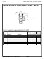
Soap Dispensing Valve Repair Parts . . . . . . . . . . . . . . . . . . . . . . . . . . . . . . . . . . . . . . . . . . . . . .22-23
Soap Recommendations and Maintenance . . . . . . . . . . . . . . . . . . . . . . . . . . . . . . . . . . . . . . . . . . . .24
Sprayhead Troubleshooting/Repair Parts . . . . . . . . . . . . . . . . . . . . . . . . . . . . . . . . . . . . . . . . . . . . 25
Manual Mixing Valve (optional) . . . . . . . . . . . . . . . . . . . . . . . . . . . . . . . . . . . . . . . . . . . . . . . . . . .26
Volume Control Valve . . . . . . . . . . . . . . . . . . . . . . . . . . . . . . . . . . . . . . . . . . . . . . . . . . . . . . . . . . .27
Vernatherm™ Thermostatic Mixing Valve . . . . . . . . . . . . . . . . . . . . . . . . . . . . . . . . . . . . . . . . .28-29
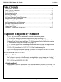
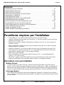
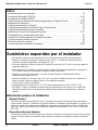
Supplies Required by Installer
• (4) 1/2" lag bolts, screws or other fasteners to anchor washfountain pedestal
• 1" hot and cold water supply lines and fittings (refer to rough-ins on pages 7-8)
• Reducing fittings and 1/2" nom. copper tubing supply lines for types with supplies from above
• Standard P-trap (refer to rough-ins on pages 7-8) (vented trap supplied by Bradley when required)
• 2" drain lines and fittings (refer to rough-ins on pages 7-8)
• 1-1/2" vent or tie pipe on fixtures vented through washfountain column (see page 9 for lengths required)
• Teflon tape or pipe dope
• 110 VAC GFI power source for 110/24 VAC UL Class II transformer supplied
• OPTIONAL: Bradley recommends installing an electrical cut-off switch to the unit. This feature
allows no accidental water delivery during regular maintenance and service.
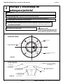
Pre-Installation Information
Terreon
®
Material
The Washfountain is constructed of Terreon
®
, a densified solid surface material composed of polyester
resin. Terreon
®
is resistant to chemicals, stains, burns and impact. Surface damage can be easily
repaired with everyday cleaners or fine-grit abrasives. Terreon
®
is NAHB certified to meet ANSI
Z124.3, Z124.6 and ANSI/ICPA SS-1-2001.
Adaptive Infrared
The sprayhead is controlled by a solenoid valve, allowing the user to activate a flow of water. The
Infrared sensor will take a few minutes to adapt to its environment when the unit is powered up.

Installation TDB3108, WF3208 Terreon
®
54" Circular
3Bradley Corporation • 215-1187 Rev. N; EN 06-915B 4/6/2007
A
D
A
•
C
O
M
P
L
I
A
N
T
54"
(1372)
19-1/2"
(495)
36"
(914)
23-1/2"
(597)
10"
(254)
34"
(864)
43-3/4"
(1111)
47-1/4"
(1200)
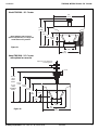
Model TDB3108 is ADA compliant.
Optional equipment may not comply with
all ADA dimensional guidelines
Model TDB3108 - 54" Circular
Model TDB3108 - 54" Circular
with optional accessories
Figure 1a
63-5/8"
(1616)
WITH
SOAP
55-1/8"
(1400)
WITHOUT
SOAP
54"
(1372)
36"
(914)
19-1/2"
(495)
55-3/4"
(1416)
47-1/4"
(1200)
43-3/4"
(1111)
34"
(864)
23-1/2"
(597)
10"
(254)
6" (152)
Adjust to towel dispenser
mounting holes
Figure 1b

TDB3108, WF3208 Terreon
®
54" Circular Installation
4 4/6/2007 Bradley Corporation • 215-1187 Rev. N; EN 06-915B
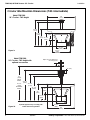
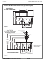
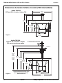
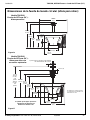
Circular Washfountain Dimensions (TAS intermediate)
61"
(1549)
WITH
SOAP
52-1/2"
(1334)
WITHOUT
SOAP
54"
(1372)
35-1/2"
(902)
19-1/2"
(495)
53-1/4"
(1353)
44-5/8"
(1143)
41-1/8"
(1045)
32"
(813)
25-1/2"
(648)
12"
(305)
6" (152)
Adjust to towel dispenser
mounting holes
TAS
54"
(1372)
19-1/2"
(495)
35-1/2"
(902)
25-1/2"
(648)
12"
(305)
32"
(813)
41-1/8"
(1045)
44-5/8"
(1133)
Model TDB3108
54" Circular - TAS Height
Model TDB3108
54" Circular - TAS Height with
optional accessories
Figure 1c
Figure 1d
Optional equipment may not comply with
all TAS dimensional guidelines

Installation TDB3108, WF3208 Terreon
®
54" Circular
5Bradley Corporation • 215-1187 Rev. N; EN 06-915B 4/6/2007
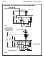
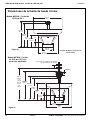
Circular Washfountain Dimensions (juvenile height)
59-1/8"
(1502)
WITH
SOAP
50-5/8"
(1286)
WITHOUT
SOAP
54"
(1372)
35-1/2"
(902)
19-1/2"
(495)
51-1/4"
(1303)
42-5/8"
(1033)
39-1/8"
(994)
30"
(762)
23-1/2"
(597)
10"
(254)
6" (152)
Adjust to towel dispenser
mounting holes
A
D
A
•
C
O
M
P
L
I
A
N
T
Optional equipment may not
comply with all ADA
dimensional guidelines
A
D
A
•
C
O
M
P
L
I
A
N
T
54"
(1372)
19-1/2"
(495)
35-1/2"
(902)
23-1/2"
(597)
10"
(254)
30"
(762)
39-1/8"
(994)
42-5/8"
(1083)
Model TDB3108
54" Circular - Juvenile Height
Model TDB3108
54" Circular - Juvenile Height
with optional accessories
Figure 1e
Figure 1f
Optional equipment may not comply with
all ADA or TAS dimensional guidelines

TDB3108, WF3208 Terreon
®
54" Circular Installation
6 4/6/2007 Bradley Corporation • 215-1187 Rev. N; EN 06-915B
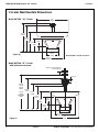
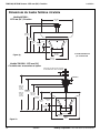
Circular Washfountain Dimensions
63-5/8"
(1616)
WITH
SOAP
55-1/8"
(1400)
WITHOUT
SOAP
54"
(1372)
37-1/2"
(953)
19-1/2"
(495)
55-3/4"
(1416)
47-1/4"
(1200)
43-3/4"
(1111)
34"
(864)
23-1/2"
(597)
10"
(254)
6" (152)
Adjust to towel dispenser
mounting holes
54"
(1372)
19-1/2"
(495)
37-1/2"
(953)
23-1/2"
(597)
10"
(254)
34"
(864)
43-3/4"
(1111)
47-1/4"
(1200)
Model WF3208 is not ADA compliant.
Model WF3208 - 54" Circular
Model WF3208 - 54" Circular
with optional accessories
Figure 1g
Figure 1h

Installation TDB3108, WF3208 Terreon
®
54" Circular
7Bradley Corporation • 215-1187 Rev. N; EN 06-915B 4/6/2007
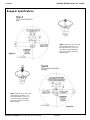
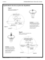
Rough-In Specifications
NOTE: Supply lines for one to two
washfountains should be 1"; for
three washfountains, 1-1/4". For
more than three washfountains,
pipe sizes should be increased
proportionately.
NOTE: Supply lines for one to two
washfountains should be 1"; for
three washfountains, 1-1/4". For
more than three washfountains,
pipe sizes should be increased
proportionately.
Figure 2a
Figure 2b

TDB3108, WF3208 Terreon
®
54" Circular Installation
8 4/6/2007 Bradley Corporation • 215-1187 Rev. N; EN 06-915B
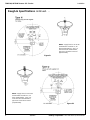
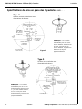
Rough-In Specifications continued . . .
NOTE: Supply lines for one to two
washfountains should be 1"; for
three washfountains, 1-1/4". For
more than three washfountains,
pipe sizes should be increased
proportionately.
NOTE: Supply lines for one to two
washfountains should be 1"; for
three washfountains, 1-1/4". For
more than three washfountains,
pipe sizes should be increased
proportionately.
Figure 2c
Figure 2d

Installation TDB3108, WF3208 Terreon
®
54" Circular
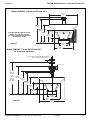
9Bradley Corporation • 215-1187 Rev. N; EN 06-915B 4/6/2007
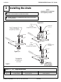
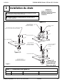
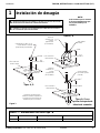
1
Installing the drain
NOTE:
All piping shown in dotted lines
to be supplied by installer.
ROUGH IN SUPPLY AND DRAIN PIPING AS REQUIRED FOR YOUR INSTALLATION (SEE
PAGES 7-8 FOR ROUGH-INS OF OPTIONAL INSTALLATIONS)
A
ASSEMBLE THE DRAIN TO THE DIMENSION SHOWN IN FIGURE 3 FOR THE BOWL
YOU ARE INSTALLING.
B
Centerline of
Washfountain
Centerline of
Washfountain
Centerline of
Washfountain
See rough-ins
on Pages 7-8
for dimensions
not shown
Types B, H
Types A, O
With Tie Pipe
Bracket Option
Types A, O
2" NPT Coupling if Tie
Pipe is not required
(Supplied by Installer)
Vent
or
Tie Pipe
(Supplied by Installer)
Vent
or
Tie Pipe
(Supplied by Installer)
Vented Trap
(111-024)
Optional
Tie Pipe Bracke
t
(S70-082)
4"
(102)
4"
(102)
B – See Table 1
B – See Table 1
B – See Table 1
4"
(102)
Figure 3
Dim Standard Height Juvenile Height TAS
B 23-3/8" (594mm) 22-1/2" (572mm) 24-1/2" (622mm)
Table 1 — “B” Trap Dimensions

TDB3108, WF3208 Terreon
®
54" Circular Installation
10 4/6/2007 Bradley Corporation • 215-1187 Rev. N; EN 06-915B
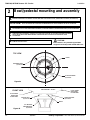
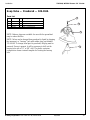
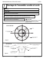
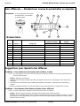
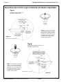
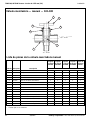
2
Bowl/pedestal mounting and assembly
CAUTION:
Bowl surface is very smooth. Approximate
weight of bowl is 190 pounds. Handle with Care!
POSITION THE PEDESTAL AT DESIRED LOCATION AND MARK THE POSITION OF THE (4) MOUNTING LOCATIONS (SEE FIGURE 4A).
PLACE TAS SPACER ON FLOOR OVER THE MOUNTING HOLES. PLACE PEDESTAL ON TOP OF THE SPACER.
A
SECURE PEDESTAL TO FLOOR WITH SUITABLE FASTENERS, 1/2" ANCHORS AND BOLTS (SUPPLIED BY INSTALLER). DO NOT OVERTIGHTEN.
B
USING THREE OR FOUR PEOPLE, CAREFULLY LIFT BOWL (SEE FIGURE 4B) ON TO PEDESTAL MAKING SURE DRAIN
HOLES LINE UP WITH FLOOR DRAIN AND MATE THREAD RODS WITH SLOTTED HOLES IN PEDESTAL USING
LOCATOR RIBS.
C
TAS OPTION:
USING 1/4" WING NUTS AND WASHERS, SECURE THE BOWL TO THE
PEDESTAL IN FOUR PLACES.
D
DRAIN
TOP VIEW
FRONT VIEW
TDB 3108 BOWL - 190 LBS.
THREADED RODS
(4) PLACES
LOCATOR RIBS
(4) PLACES
1/4" WASHERS
AND WING NUTS
(4) PLACES
THREADED RODS
(4) PLACES
FLOOR MOUNTING
(4) PLACES
DRAIN
PLACE HANDS
HERE WHEN
LIFTING BOWL
PLACE HANDS
HERE WHEN
LIFTING BOWL
Figure 4a
Figure 4b

Installation TDB3108, WF3208 Terreon
®
54" Circular
11Bradley Corporation • 215-1187 Rev. N; EN 06-915B 4/6/2007
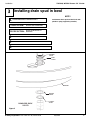
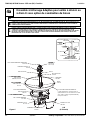
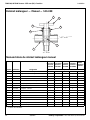
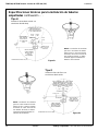
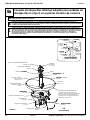
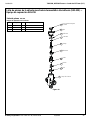
3
Installing drain spud in bowl
NOTE!
Seal between drain spud and drain hole with
plumber’s putty (supplied by installer).
LOOSELY ATTACH THE DRAIN SPUD TO THE BOWL WITH THE
LOCKNUT AND WASHER AS SHOWN IN FIGURE 5.
A
TIGHTEN THE SPUD AND LOCK NUT AGAINST THE BOWL.
B
SECURE THE STRAINER TO DRAIN SPUD WITH THE SCREWS PROVIDED.
C
CONNECT SPUD (OR B TRAP OR TIE PIPE BRACKET) TO DRAIN.
D
ATTACH B TRAP TO DRAIN SPUD.
B TRAP OPTION:
ATTACH TIE PIPE BRACKET TO
DRAIN SPUD.
TIE PIPE OPTION:
STRAINER
S45-067
SPUD
112-015
BOWL
WASHER
142-068
LOCKNUT
161-021
DRAIN PRE-PACK
S45-273
Figure 5

TDB3108, WF3208 Terreon
®
54" Circular Installation
12 4/6/2007 Bradley Corporation • 215-1187 Rev. N; EN 06-915B
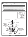
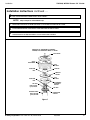
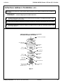
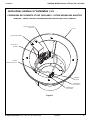
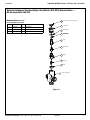
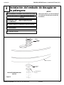
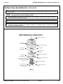
Adaptive infrared assembly for A drain and O drain units
without Tie Pipe option
4a
SUPPORT TUBE
GASKET
125-011
SUPPORT TUBE
(STD) S57-005
(JUV) S57-006
TIE ROD PRE-PACK
S45-1336
1/2" SUPPLY TUBE
PRE-PACK
S45-1466
PRE-PACK
S45-055
TIE BAR
PEDESTAL ASSY.
S17-242
COVER
107-099 (A)
107-179 (O)
I.R. MODULE ASSY.
S50-344
SPRAYHEAD
S05-054
TIE ROD
176-008A
DRAIN
S45-273
VALVE ASSY.
S50-369
ACCESS PANEL
186-1456
TERREON® DEEP BOWL
(ADA bowl shown, classic
bowl is optional)
Part No. varies with color of bowl.
Contact your local Bradley Rep.
for assistance
NUT
A/O
(A shown)
COVER
TIE ROD
PRE-PACK
TIE
ROD
COUPLING
NUT
SECTION VIEW OF
A/O UNIT ASSEMBLY
SPRAYHEAD
ACTUATOR
MODULE
ASSY.
TIE
BAR
SUPPLY TUBE
Figure 6
INSTALL HEMMED END (NOT SHARP END) OF SUPPORT TUBE WITH GASKET ONTO BOWL (SEE FIGURE 6).
A
CONNECT 1/2" SUPPLY TUBING TO SPRAYHEAD WITH 3/8" NPT TO 1/2" TUBE CONNECTOR AND PLACE SPRAYHEAD ONTO
SUPPORT TUBE. RUN THE TUBING DOWN THROUGH THE SUPPORT TUBE AND CONNECT TO VALVE TUBE CONNECTOR.
B
PLACE THE UPPER TIE BAR (NOTCHED AT BOTH CORNERS OF EACH END) ON TOP OF SPRAYHEAD. CONNECT THE LONGER TIE
ROD TO THE 4-1/4" TIE ROD USING THE COUPLING NUT WITH HEX HEAD SET SCREWS. RUN THE TIE ROD ASSEMBLY DOWN
THROUGH UPPER TIE BAR (SEE FIGURE 6 INSET) AND SECURE FROM UNDERNEATH THE BOWL USING LOWER TIE BAR (NO
NOTCHES) AND HEX NUT WITH SOCKET HEAD SET SCREW.
C

Installation TDB3108, WF3208 Terreon
®
54" Circular
13Bradley Corporation • 215-1187 Rev. N; EN 06-915B 4/6/2007
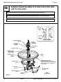
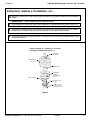
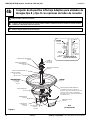
Installation Instructions continued . . .
TOP COVER
Figure 7
I.R. MODULE
ASSEMBLY
S50-344
SPRAYHEAD
S05-054
SUPPORT TUBE
(STD.) S57-005
(JUV.) S57-006
COUPLING
NUT
SPACER
SOAP
DISPENSER
TIE ROD
(STD.) 21-5/8"
(JUV.) 18-1/8"
UNIT WITH “A” DRAIN AND I.R. MODULE
SHOWN, ALSO AVAILABLE WITH “O” DRAIN
COUPLING
NUT
4-1/4"
TIE ROD
8-5/8"
TIE ROD
MODULE
COVER
TIE BAR
PLACE THE INFRARED MODULE ASSEMBLY ON TOP OF SPRAYHEAD. ROTATE UNTIL INFRARED MODULE LOCKS IN WITH TIE BAR.
DROP TWO INFRARED MODULE WIRES DOWN TO VALVE ASSEMBLY.
D
SECURE INFRARED MODULE COVER AND TOP COVER WITH ACORN NUT AND SET SCREW.
E
FOR O UNIT: INSTALL 1/2" NOMINAL COPPER TUBING SUPPLY LINES (PASS THEM THROUGH HOLES IN COVER DOWN
THROUGH SUPPORT COLUMN) AND CONNECT TO STOPS USING SUITABLE FITTINGS.
F
FOR UNITS WITH SOAP OPTION, INSTALL THE SPACER, SOAP DISPENSER AND COVER USING THE THIRD TIE ROD (8-5/8" LONG)
AND SECOND COUPLING NUT AS SHOWN (SEE FIGURE 7). SECURE WITH ACORN NUT AND SET SCREW.
•
NOTE! Skip to step E for units without soap.

TDB3108, WF3208 Terreon
®
54" Circular Installation
14 4/6/2007 Bradley Corporation • 215-1187 Rev. N; EN 06-915B
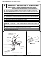
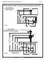
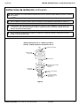
Adaptive infrared assembly for B drain and H drain units
with Tie Pipe option
4b
SUPPORT TUBE
GASKET
125-011
SUPPORT TUBE
(STD) S57-005
(JUV) S57-006
PRE-PACK
S45-1466
VENTED TRAP
111-024
TIE BAR
PRE-PACK
S45-056
PEDESTAL ASSY.
S17-242
COVER
107-185 (B)
107-048 (H)
I.R. MODULE ASSY.
S50-344
1/2" SUPPLY TUBE
SPRAYHEAD
S05-054
DRAIN
S45-273
VALVE ASSY.
S50-369
ACCESS PANEL
186-1456
TERREON® DEEP BOWL
(ADA bowl shown, classic bowl
is optional) Part No. varies with color
of bowl. Contact your Bradley Rep.
for assistance.
B/H
(B shown)
COVER
SECTION VIEW OF
B/H UNIT ASSEMBLY
SPRAYHEAD
ACTUATOR
MODULE
ASSY.
TIE
BAR
SUPPLY
TUBE
Figure 8
INSTALL HEMMED END (NOT SHARP END) OF SUPPORT TUBE WITH GASKET ONTO BOWL (SEE FIGURE 8).
A
CONNECT 1/2" SUPPLY TUBING TO SPRAYHEAD WITH 3/8" NPT TO 1/2" TUBE CONNECTOR AND PLACE SPRAYHEAD ONTO
SUPPORT TUBE. RUN THE TUBING DOWN THROUGH THE SUPPORT TUBE AND CONNECT TO VALVE TUBE CONNECTOR.
B
INSERT THE 1-1/2" VENT PIPE (SUPPLIED BY INSTALLER) DOWN THROUGH THE SUPPORT TUBE AND THREAD INTO VENTED TRAP.
C

Installation TDB3108, WF3208 Terreon
®
54" Circular
15Bradley Corporation • 215-1187 Rev. N; EN 06-915B 4/6/2007
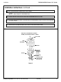
Installation Instructions continued . . .
Figure 9
INFRARED
MODULE
ASSEMBLY
S50-344
SPRAYHEAD
S05-054
SUPPORT TUBE
(STD.) S57-005
(JUV.) S57-006
SPACER
SOAP
DISPENSER
TIE BAR
UNIT WITH “B” DRAIN AND I.R. MODULE
SHOWN, ALSO AVAILABLE WITH “H” DRAIN
TOP COVER
PLACE THE INFRARED MODULE ASSEMBLY ON TOP OF SPRAYHEAD. ROTATE UNTIL INFRARED MODULE LOCKS IN WITH TIE BAR.
DROP TWO INFRARED MODULE WIRES DOWN TO VALVE ASSEMBLY.
D
POSITION THE UPPER TIE BAR SLIGHTLY BELOW THE MODULE (SEE FIGURE 8 INSET ON PREVIOUS PAGE) OR SOAP DISPENSER
(SEE FIGURE 9) AND FASTEN SECURELY TO VENT PIPE WITH SET SCREWS PROVIDED. SECURE TOP COVER TO TIE BAR WITH TWO
CAP SCREWS PROVIDED.
E
FOR B UNIT: INSTALL 1/2" NOMINAL COPPER TUBING SUPPLY LINES (PASS THEM THROUGH HOLES IN COVER DOWN
THROUGH SUPPORT COLUMN) AND CONNECT SUPPLY LINES TO STOPS USING SUITABLE FITTINGS.
F
FOR UNITS WITH SOAP OPTION, SLIDE THE SPACER AND SOAP DISPENSER OVER THE 1-1/2" PIPE.
•
NOTE! Skip to step E for units without soap.

TDB3108, WF3208 Terreon
®
54" Circular Installation
16 4/6/2007 Bradley Corporation • 215-1187 Rev. N; EN 06-915B
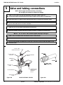
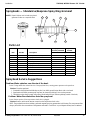
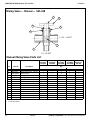
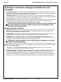
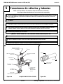
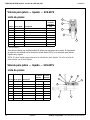
5
Valve and tubing connections
TEE
269-764
VOLUME CONTROL
S02-045
THERMOSTATIC
MIXING VALVE
ASSEMBLY
S67-597
STOP/CHECK
VALVE
1/2" DIA. TUBE
FROM SPRAYHEAD
1/2" DIA. TUBE
R68-600012
SOLENOID
ASSY.
S08-055
FLEXIBLE
HOSE
FILTER WASHER
Figure 10a
Figure 10b
NUT
MALE TUBE
CONNECTOR
TUBING
VALVE ASSEMBLY S50-369
NOTE: Flush supply lines before making connections.
Do not apply pipe sealant to compression fittings.
CONNECT 1/2" DIA. TUBING TO TEE AND SOLENOID ASSEMBLY, TWO PLACES. THE MALE CONNECTOR
(FIGURE 10B) FOR THE VALVE ASSEMBLY WILL REMAIN TIGHT AND LEAKPROOF WHEN TUBING IS CUT AND INSTALLED PROPERLY.
FOLLOW THE PROCEDURES BELOW WHEN INSTALLING TUBING TO ENSURE THAT YOU ACHIEVE A LEAKPROOF SEAL.
A
USING A SHARP RAZOR, CUT TUBING SQUARELY AND REMOVE ANY BURRS. DO NOT PINCH OR CRUSH END OF TUBING.
•
LOOSEN NUT ON FITTING. MOISTEN END OF TUBE AND PUSH INTO FITTING UNTIL IT IS FIRMLY SEATED. TIGHTEN NUT TO SECURE
TUBE TO FITTING (MAKE SURE NUT IS SECURELY TIGHTENED).
•
IF CONNECTOR LEAKS, RESEAT TUBING ACCORDING TO ABOVE PROCEDURE. IF LEAKING PERSISTS, REPLACE MALE
CONNECTOR, OR CALL YOUR BRADLEY REPRESENTATIVE FOR ASSISTANCE.
•
HANG VALVE ASSEMBLY ON PEDESTAL BRACKET (SEE FIGURE 11 ON PAGE 17). USE WIRE TIE TO SECURE VALVES.
B
CONNECT THE 1/2" NPT FEMALE END OF THE STOP/CHECK VALVES TO THE ROUGH-INS.
C
ATTACH FLEXIBLE HOSING TO THERMOSTATIC MIXING VALVE, TWO PLACES.
D
INSERT THE FILTER WASHERS (PROVIDED) INTO THE SWIVEL NUT AT THE END OF THE SUPPLY HOSES AND CONNECT TO THE
STOP/CHECK VALVES.
E
NOTE! For “O” and “B” units (overhead supplies) Skip steps C through E

Installation TDB3108, WF3208 Terreon
®
54" Circular
17Bradley Corporation • 215-1187 Rev. N; EN 06-915B 4/6/2007
Installation Instructions continued . . .
VALVE AND TUBING CONNECTIONS - ADAPTIVE INFRARED OPTION
NOTE: FLUSH SUPPLY LINES BEFORE MAKING CONNECTIONS.
1/2" TUBE FROM
SPRAYHEAD
VOLUME
CONTROL
CHECK/STOP
VALVE
VALVE
BRACKET
PEDESTAL
FILTER
WASHER
COLD
SUPPLY
HOT
SUPPLY
Figure 11

TDB3108, WF3208 Terreon
®
54" Circular Installation
18 4/6/2007 Bradley Corporation • 215-1187 Rev. N; EN 06-915B
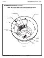
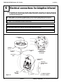
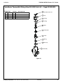
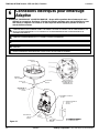
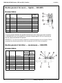
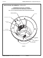
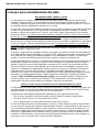
6
Electrical connections for Adaptive Infrared
START-UP NOTE: Do not use for two minutes after making power connection. The sensors will take up
to eight minutes (without being used) to adapt to the bowl if another object is detected during the
two-minute start-up period.
I.R. MODULE
S50-344
TOP VIEW MODULE
ASSEMBLY
CONNECT WIRES
AS SHOWN
VALVE ASSY.
S50-369
110/24 VAC
TRANSFORMER
S83-134
F = FEMALE CONNECT
M = MALE CONNECT
WIRE
ADAPTER
269-620
S53-261
(S53-261A) C
RED
(S53-261A) A
RED
(S53-272) B
BLACK
WINDOW
269-1351
Figure 12
CONNECT THE THREE WIRES FROM THE INFRARED MODULE ASSEMBLY TO THE VALVE ASSEMBLY. ATTACH TWO OF THE FEMALE
CONNECT WIRES TO THE SOLENOIDS AS SHOWN IN FIGURE 12. ATTACH THE MALE CONNECT WIRE TO ONE OF THE 24 VAC
TRANSFORMER LEADS. ATTACH THE REMAINING TRANSFORMER LEAD TO THE SOLENOID WIRE ADAPTER (SEE FIGURE 12).
A
CONNECT 24 VAC TRANSFORMER PROVIDED TO POWER SOURCE.
B
TURN SUPPLIES ON. OPEN CHECK/STOP VALVES COMPLETELY.
C
OPEN VOLUME CONTROL VALVE COMPLETELY AND CHECK PIPING INSTALLATION FOR LEAKS.
D
PASS YOUR HAND IN FRONT OF EACH SENSOR UNTIL AIR IS PURGED FROM THE LINES.
E

Installation TDB3108, WF3208 Terreon
®
54" Circular
19Bradley Corporation • 215-1187 Rev. N; EN 06-915B 4/6/2007
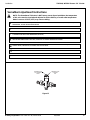
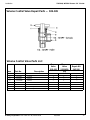
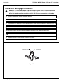
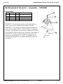
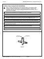
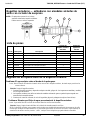
Vernatherm Ajustment Instructions
NOTE: The Vernatherm TMA valve is NOT factory preset. Upon installation, the temperature
of this valve must be checked and adjusted to ensure delivery of a safe water temperature.
Water in excess of 110°F (43°C) may cause scalding.
TEMPERATURE
ADJUSTMENT
STEM
TEMPERATURE
LOCKING
NUT
Figure 13
CHECK THE TEMPERATURE AND ADJUST IF NECESSARY (THE RANGE OF THE VALVE IS 95°F–115°F (35°C–43°C). TO ADJUST THE
TEMPERATURE, FOLLOW THE PROCEDURE BELOW:
F
CLEAN SPRAYHEAD IF NECESSARY. SEE PAGE 25 FOR SPRAYHEAD MAINTENANCE AND REPAIR PARTS. ADJUST THE VOLUME
CONTROL VALVE, IF NECESSARY, TO CONTROL THE FLOW OF WATER.
G
ATTACH PEDESTAL ACCESS PANEL WITH HARDWARE PROVIDED.
H
ATTACH KICK PLATE TO PEDESTAL BASE WITH HARDWARE PROVIDED.
I
LOOSEN TEMPERATURE LOCKING NUT WITH WRENCH.
•
ONCE DESIRED TEMPERATURE IS REACHED, TIGHTEN NUT TO PREVENT TEMPERATURE CHANGE.
•
USING A BLADE SCREWDRIVER, TURN THE ADJUSTMENT STEM COUNTERCLOCKWISE TO INCREASE THE TEMPERATURE OR
CLOCKWISE TO DECREASE THE TEMPERATURE (FIGURE 13).
•

TDB3108, WF3208 Terreon
®
54" Circular Installation
20 4/6/2007 Bradley Corporation • 215-1187 Rev. N; EN 06-915B
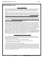
Cleaning/Maintenance Instructions for Terreon®
Material Description: Terreon
®
is a NAHB Certified densified solid surface material composed of polyester
resin and is resistant to chemicals, stains, burns and impact. Surface damage can be easily repaired with
everyday cleansers or fine grit abrasives.
Routine Cleaning: Clean daily or as often as conditions require using a standard commercial or household
cleaner such as Formula 409
®
or Windex
®
.
Stubborn Stains: Remove tough stains with Ajax
®
, Comet
®
, or Soft-Scrub
®
and a green Scotch-Brite
®
pad or
lightly sand in a circular motion with 240 grit wet/dry sandpaper. The finish can be renewed with a maroon
Scotch-Brite pad.
Special Situations for Material
Scratches: Remove scratches with a green Scotch-Brite
®
pad. The finish can then be renewed with a maroon
Scotch-Brite
®
pad.
Hard Water Deposits: Remove hard water deposits with a mild solution of vinegar and water. Always rinse
the unit thoroughly after cleaning.
Restoring the Surface: Use Hope’s
®
Solid Surface cleaner and polish to refresh and protect the Terreon
Solid Surface material. Bradley recommends additional care and maintenance for the darker colored Terreon,
for complete instructions on this additional maintenance see Bradley document #1505.
IMPORTANT:
DO NOT USE STRONG ACID OR ALKALINE CHEMICALS AND CLEANSERS TO
CLEAN TERREON. IF THESES CHEMICALS COME IN CONTACT WITH THE TERREON
SURFACE WIPE THEM OFF IMMEDIATELY AND RINSE WITH SOAPY WATER. AVOID CONTACT
WITH HARSH CHEMICALS SUCH AS PAINT REMOVER, BLEACH, ACETONE, ETC. AVOID
CONTACT WITH HOT PANS AND OBJECTS.
Repair Kits: Terreon
®
repair kits are available. Contact your Bradley representative or distributor for part
numbers and pricing.
NOTE: Repair kits are made to order and have a shelf life of 30 days.
Brand Names: Use of brand names is intended only to indicate a type of cleaner. This does not constitute an
endorsement, nor does the omission of any brand name cleaner imply its inadequacy. Many products named
are regional in distribution, and can be found in local supermarkets, department and hardware stores, or
through your cleaning service. It is emphasized that all products should be used in strict accordance with
package instructions.
Cleaning/Maintenance Instructions for Gel-coated Fiberglass
Material Description: The Terreon
®
Washfountains referenced in this installation manual use a gel-coated
fiberglass pedestal.
Routine Cleaning: The gel-coated pedestal should be cleaned daily or as often as needed with a mild solution
of detergent and water. Always use a soft cloth to avoid damage to the finish.
Repair Kits: There are no repair kits available for fiberglass materials. However, replacement parts are
available, contact your Bradley representative for pricing and part numbers.
IMPORTANT: DO NOT EXPOSE GEL-COATED FIBERGLASS TO SOLVENTS AS THEY
WILL DAMAGE THE MATERIAL AND MAY CREATE HARMFUL FUMES.
Brand Names: Use of brand names is intended only to indicate a type of cleaner. This does not constitute an
endorsement, nor does the omission of any brand name cleaner imply its inadequacy. Many products named are
regional in distribution, and can be found in local supermarkets, department and hardware stores, or through your
cleaning service. It is emphasized that all products should be used in strict accordance with package instructions.
La page est en cours de chargement...
La page est en cours de chargement...
La page est en cours de chargement...
La page est en cours de chargement...
La page est en cours de chargement...
La page est en cours de chargement...
La page est en cours de chargement...
La page est en cours de chargement...
La page est en cours de chargement...
La page est en cours de chargement...
La page est en cours de chargement...
La page est en cours de chargement...
La page est en cours de chargement...
La page est en cours de chargement...
La page est en cours de chargement...
La page est en cours de chargement...
La page est en cours de chargement...
La page est en cours de chargement...
La page est en cours de chargement...
La page est en cours de chargement...
La page est en cours de chargement...
La page est en cours de chargement...
La page est en cours de chargement...
La page est en cours de chargement...
La page est en cours de chargement...
La page est en cours de chargement...
La page est en cours de chargement...
La page est en cours de chargement...
La page est en cours de chargement...
La page est en cours de chargement...
La page est en cours de chargement...
La page est en cours de chargement...
La page est en cours de chargement...
La page est en cours de chargement...
La page est en cours de chargement...
La page est en cours de chargement...
La page est en cours de chargement...
La page est en cours de chargement...
La page est en cours de chargement...
La page est en cours de chargement...
La page est en cours de chargement...
La page est en cours de chargement...
La page est en cours de chargement...
La page est en cours de chargement...
La page est en cours de chargement...
La page est en cours de chargement...
La page est en cours de chargement...
La page est en cours de chargement...
La page est en cours de chargement...
La page est en cours de chargement...
La page est en cours de chargement...
La page est en cours de chargement...
La page est en cours de chargement...
La page est en cours de chargement...
La page est en cours de chargement...
La page est en cours de chargement...
La page est en cours de chargement...
La page est en cours de chargement...
La page est en cours de chargement...
La page est en cours de chargement...
La page est en cours de chargement...
La page est en cours de chargement...
La page est en cours de chargement...
La page est en cours de chargement...
La page est en cours de chargement...
-
 1
1
-
 2
2
-
 3
3
-
 4
4
-
 5
5
-
 6
6
-
 7
7
-
 8
8
-
 9
9
-
 10
10
-
 11
11
-
 12
12
-
 13
13
-
 14
14
-
 15
15
-
 16
16
-
 17
17
-
 18
18
-
 19
19
-
 20
20
-
 21
21
-
 22
22
-
 23
23
-
 24
24
-
 25
25
-
 26
26
-
 27
27
-
 28
28
-
 29
29
-
 30
30
-
 31
31
-
 32
32
-
 33
33
-
 34
34
-
 35
35
-
 36
36
-
 37
37
-
 38
38
-
 39
39
-
 40
40
-
 41
41
-
 42
42
-
 43
43
-
 44
44
-
 45
45
-
 46
46
-
 47
47
-
 48
48
-
 49
49
-
 50
50
-
 51
51
-
 52
52
-
 53
53
-
 54
54
-
 55
55
-
 56
56
-
 57
57
-
 58
58
-
 59
59
-
 60
60
-
 61
61
-
 62
62
-
 63
63
-
 64
64
-
 65
65
-
 66
66
-
 67
67
-
 68
68
-
 69
69
-
 70
70
-
 71
71
-
 72
72
-
 73
73
-
 74
74
-
 75
75
-
 76
76
-
 77
77
-
 78
78
-
 79
79
-
 80
80
-
 81
81
-
 82
82
-
 83
83
-
 84
84
-
 85
85


Bradley Smoker Terreon WF3208 Manuel utilisateur
- Taper
- Manuel utilisateur
- Ce manuel convient également à
dans d''autres langues
Autres documents
-
Bradley Terreon WF3204 Guide d'installation
-
-
-
ALPATEC F 10 FC Le manuel du propriétaire
-
-
-
-
Speakman SE-362 Guide d'installation
-
Triangle S01 Manuel utilisateur
-
ROOMS TO GO 85100837 Assembly Instructions