LG DLE3400W Le manuel du propriétaire
- Catégorie
- Sèche-linge
- Taper
- Le manuel du propriétaire

www.lg.com
Read this owner’s manual thoroughly before operating the appliance and keep it handy for
reference at all times.
OWNER'S MANUAL
DRYER
Copyright © 2020 LG Electronics Inc. All Rights Reserved.
MFL70442646
Rev.00_013120
DLE3400*
ENGLISH FRANÇAIS

TABLE OF CONTENTS
2
3 PRODUCT FEATURES
4 SAFETY INSTRUCTIONS
4 IMPORTANT SAFETY INSTRUCTIONS
9 PRODUCT OVERVIEW
9 Parts
9 Accessories
10 INSTALLATION
10 Installation Overview
10 Product Specifications
11 Installation Location Requirements
12 Clearances
14 Leveling the Dryer
15 Reversing the Door
16 Installing the Side Vent Kit
17 Stacking the Dryer
18 Venting the Dryer
20 Connecting Gas Dryers
22 Connecting Electric Dryers
23 Special Electrical Requirements
23 Final Installation Check
24 Installation Test (Duct Check)
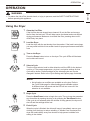
27 OPERATION
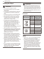
27 Using the Dryer
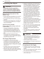
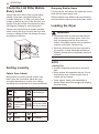
28 Check the Lint Filter Before Every Load
28 Sorting Laundry
28 Loading the Dryer
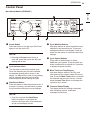
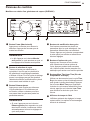
29 Control Panel
31 Cycle Guide
32 Cycle Modifier Buttons
32 Option Buttons
33 Special Functions
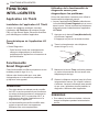
34 SMART FUNCTIONS
34 LG ThinQ Application
34 Smart Diagnosis™ Feature
35 MAINTENANCE
35 Regular Cleaning
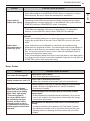
37 TROUBLESHOOTING
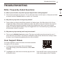
37 FAQs: Frequently Asked Questions
37 User Support Videos
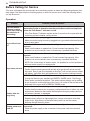
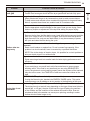
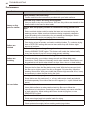
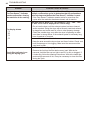
38 Before Calling for Service
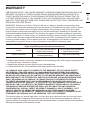
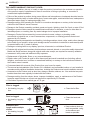
43 WARRANTY

3
PRODUCT FEATURES
ENGLISH
PRODUCT FEATURES
Easy-to-Use Control Panel
Rotate the cycle selector knob to select the desired dry cycle. Add cycle options or adjust settings with the
touch of a button.
Easy-Access Reversible Door
The wide-opening door provides easy access for loading and unloading. The door hinge can be reversed to
adjust for installation location.
Flow Sense™ Duct Blockage Sensing System Indicator
The Flow Sense™ duct blockage sensing system detects and alerts you to restrictions in the installed
household ductwork that reduce exhaust airflow through the dryer. If you see the alert: Clean or repair the
ducts to remove the restrictions. Keep your ducts clean to help increase efficiency and reduce long drying
times caused by blocked ducts.
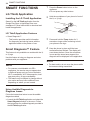
Smart Diagnosis™
Should you experience any technical difficulty with your dryer, it has the capability of transmitting data via your
telephone to the Customer Information Center. The call center agent records the data transmitted from your
machine and uses it to analyze the issue, providing a fast and effective diagnosis.
C
E
R
T
I
F
I
E
D
D
E
S
I
G
N

4
SAFETY INSTRUCTIONS
SAFETY INSTRUCTIONS
READ ALL INSTRUCTIONS BEFORE USE
Your safety and the safety of others are very important.
We have provided many important safety messages in this manual and on your appliance. Always
read and follow all safety messages.
This is the safety alert symbol.
This symbol alerts you to potential hazards that can kill or injure you and others.
All safety messages will follow the safety alert symbol and either the word WARNING or
CAUTION. These words mean:
WARNING
You may be killed or seriously injured if you do not follow instructions.
CAUTION
You may be slightly injured or cause damage to the product if you do not follow instructions.
All safety messages will tell you what the potential hazard is, tell you how to reduce the chance of
injury, and tell you what may happen if the instructions are not followed.
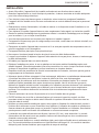
IMPORTANT SAFETY INSTRUCTIONS
WARNING
To reduce the risk of explosion, fire, death, electric shock, scalding or injury to persons
when using this product, follow basic precautions, including the following:
FIRE OR EXPLOSION HAZARD
• Do not store or use gasoline or other flammable vapors and liquids in the vicinity of this or any other
appliance.
• WHAT TO DO IF YOU SMELL GAS
− Do not try to light any appliance.
− Do not touch any electrical switch; do not use any phone in your building.
− Clear the room, building or area of all occupants.
− Immediately call your gas supplier from a neighbor’s phone. Follow the gas supplier’s instructions.
− If you cannot reach your gas supplier, call the fire department.
• Installation and service must be performed by a qualified installer, service agency or your gas supplier.

5
SAFETY INSTRUCTIONS
ENGLISH
INSTALLATION
• Before use, the appliance must be properly installed as described in this manual.
• Connect to a properly rated, protected, and sized power circuit to avoid electrical overload.
• To reduce the risk of severe injury or death, follow all installation instructions.
• The appliance must be installed and electrically grounded by qualified service personnel in accordance
with local codes.
• Disconnect the power cord, house fuse or circuit breaker before installing or servicing the appliance.
• When moving or installing the product in a different location, call qualified service personnel for
installation and service.
• Keep packing materials out of the reach of children. Packaging material can be dangerous for children.
There is a risk of suffocation.
• Moving or installation of the appliance requires two or more people.
• This appliance is not designed for maritime use or for mobile installations such as in RVs, trailers, or
aircraft.
• Store and install the appliance where it will not be exposed to temperatures below freezing or exposed
to outdoor weather conditions.
• This appliance must be positioned near to an electrical power supply.
• Do not, under any circumstances, cut or remove the third (ground) prong from the power cord.
• When installing or moving the appliance, be careful not to pinch, crush, or damage the power cord.
• Do not install the appliance in humid spaces.
• Destroy the carton, plastic bag, and other packing materials after the appliance is unpacked. Children
might use them for play. Cartons covered with rugs, bedspreads, or plastic sheets can become airtight
chambers.
• Adhere to all industry recommended safety procedures including the use of long sleeved gloves and
safety glasses.
• Never attempt to operate this appliance if it is damaged, malfunctioning, partially disassembled, or has
missing or broken parts, including a damaged cord or plug.
• Do not install a clothes dryer with flexible plastic venting materials. If flexible metal (foil type) duct is
installed, it must be of a specific type identified by the appliance manufacturer as suitable for use with
clothes dryers. Flexible venting materials are known to collapse, be easily crushed, and trap lint. These
conditions will obstruct clothes dryer airflow and increase the risk of fire.
• Place the dryer at least 18 inches above the floor for a garage installation.
• Do not use sheet metal screws or other fasteners which extend into the duct that could catch lint and
reduce the efficiency of the exhaust system. Secure all joints with duct tape.
• Use only rigid, semi-rigid or flexible metal 4-inch diameter duct inside the dryer cabinet or for exhausting
to the outside. Use of plastic or other combustible ductwork may cause a fire. Punctured ductwork may
cause a fire if it collapses or becomes otherwise restricted in use or during installation.
• The exhaust duct must be 4 inches (10.2 cm) in diameter with no obstructions. The exhaust duct should
be kept as short as possible. Make sure to clean any old ducts before installing your new dryer.
• Rigid, semi-rigid or flexible metal ducting is recommended for use between the dryer and the wall. All
non-rigid metal transition duct must be UL-listed. Use of other materials for transition duct could affect
drying time.
• Ductwork is not provided with the dryer, and you should obtain the necessary ductwork locally. The end
cap should have hinged dampers to prevent backdraft when the dryer is not in use.

6
SAFETY INSTRUCTIONS
• Gas dryers MUST be exhausted to the outside.
• The dryer exhaust system must be exhausted to the outside of the dwelling. If the dryer is not
exhausted outdoors, some fine lint and large amounts of moisture will be expelled into the laundry area.
An accumulation of lint in any area of the home may create a health and fire hazard.
• Do not install near another heat source such as a stove, oven or heater.
• Keep area around the exhaust opening and adjacent surrounding areas free from the accumulation of
lint, dust, and dirt.
• The appliance must not be supplied through an external switching device, such as a timer, or connected
to a circuit that is regularly switched on and off by a utility.
OPERATION
• Repair or immediately replace all power cords that have become frayed or otherwise damaged. Do not
use a cord that shows cracks or abrasion damage along its length or at either end.
• If you detect a strange sound, a chemical or burning smell, or smoke coming from the appliance, unplug
it immediately, and contact an LG Electronics customer information center.
• Never unplug the appliance by pulling on the power cord. Always grip the plug firmly and pull straight
out from the outlet.
• Do not use an extension cord or adapter with this appliance.
• Do not grasp the power cord or touch the appliance controls with wet hands.
• Do not modify or extend the power cord.
• If the product has been submerged, contact an LG Electronics customer information center for
instructions before resuming use.
• Do not store or use gasoline or other flammable vapors and liquids in the vicinity of this or any other
appliance.
• Keep the area underneath and around your appliances free of combustible materials (lint, paper, rags,
etc.), gasoline, chemicals and other flammable vapors and liquids.
• This appliance is not intended for use by persons (including children) with reduced physical, sensory or
mental capabilities, or lack of experience and knowledge, unless they have been given supervision or
instruction concerning the use of the appliance by a person responsible for their safety.
• Read all instructions before using the appliance and save these instructions.
• Use this appliance only for its intended purpose.
• Do not abuse, sit on, or stand on the door of the appliance.
• Do not allow children to play on, in or with the appliance. Close supervision of children is necessary
when the appliance is used near children.
• Do not tamper with controls.
• In the event of a gas leak (propane gas, LP gas, etc.) do not operate this or any other appliance. Open
a window or door to ventilate the area immediately.
• Under certain conditions, hydrogen gas may be produced in a hot-water system that has not been used
for two weeks or more. HYDROGEN GAS IS EXPLOSIVE. If the hot-water system has not been used
for such a period, before using the appliance turn on all hot water faucets and let the water flow from
each for several minutes. This will release any accumulated hydrogen gas. As the gas is flammable, do
not smoke or use an open flame during this time.

7
SAFETY INSTRUCTIONS
ENGLISH
• Fix the drain hose securely in place.
• Do not put oily or greasy clothing, candles or flammable materials on top of the appliance.
• Do not use fabric softeners or products to eliminate static unless recommended by the manufacturer of
the fabric softener or product.
• Do not reach into the appliance if the drum is moving.
• Do not dry articles that have been previously cleaned in, washed in, soaked in, soiled with or spotted
with gasoline, dry cleaning solvents, vegetable oil, cooking oil or other flammable or explosive
substances, as they give off vapors that could ignite or explode.
• Do not use heat to dry articles containing foam rubber or similarly textured rubber-like materials.
• Do not store plastic, paper, or clothing that may burn or melt on top of the dryer during operation.
• Always check the inside of the appliance for foreign objects.
• Gas appliances can cause minor exposure to four potentially hazardous substances, namely benzene,
carbon monoxide, formaldehyde, and soot, caused primarily by the incomplete combustion of natural
gas or LP fuels.
• Properly adjusted dryers will minimize incomplete combustion. Exposure to these substances can be
minimized further by properly venting the dryer to the outdoors.
• Do not place items exposed to cooking oils in your dryer. Items contaminated with cooking oils may
contribute to a chemical reaction that could cause a load to catch fire.
To reduce the risk of fire due to contaminated loads, the final part of a tumble dryer cycle occurs without
heat (cool down period). Avoid stopping a tumble dryer before the end of the drying cycle unless all
items are quickly removed and spread out so that the heat is dissipated.
• Do not let children or pets climb inside the dryer drum.
• Do not put living animals such as pets inside the product.
• Do not put any part of your body, such as your hands or feet, or metal objects under the product.
• Do not let your hand get pinched when opening or closing the dryer door.
MAINTENANCE
• Do not repair or replace any part of the appliance. All repairs and servicing must be performed by
qualified service personnel unless specifically recommended in this Owner’s Manual. Use only
authorized factory parts.
• Do not disassemble or repair the appliance by yourself.
• Remove any dust or foreign matter from the power plug pins.
• Disconnect this appliance from the power supply before cleaning and attempting any user maintenance.
Turning the controls to the OFF position does not disconnect this appliance from the power supply.
• Remove the door before the appliance is removed from service or discarded to avoid the danger of
children or small animals getting trapped inside.
• Unplug the appliance before cleaning to avoid the risk of electric shock.
• Clean the lint filter before or after each load.
• The interior of the appliance and exhaust duct should be cleaned periodically by qualified service
personnel.

8
SAFETY INSTRUCTIONS
GROUNDING INSTRUCTIONS
• Improper connection of the equipment-grounding conductor can result in a risk of electric shock. Check
with a qualified electrician or service personnel if you are in doubt whether the appliance is properly
grounded. Do not modify the plug provided with the appliance; if it will not fit the outlet, have a proper
outlet installed by a qualified electrician.
• The appliance must be grounded. In the event of a malfunction or breakdown, grounding will reduce
the risk of electric shock by providing a path of least resistance for electric current. The appliance is
equipped with a cord having an equipment-grounding conductor and a grounding plug. The plug must
be plugged into an appropriate outlet that is installed and grounded in accordance with all local codes
and ordinances.
• This dryer must be plugged into a properly grounded outlet. Electrical shock may result if the dryer is
not properly grounded. Have the wall outlet and circuit checked by a qualified electrician to make sure
the outlet is properly grounded. Failure to follow these instructions may create an electric shock hazard
and/or a fire hazard.
Risk of Fire
Install the clothes dryer according to the manufacturer’s instructions and local codes.
• Clothes dryer installation must be performed by a qualified installer.
• Do not install a clothes dryer with flexible plastic venting materials. If flexible metal (foil type) duct is
installed, it must be of a specific type identified by the appliance manufacturer as suitable for use with
clothes dryers. Flexible venting materials are known to collapse, be easily crushed, and trap lint. These
conditions will obstruct clothes dryer airflow and increase the risk of fire.
• To reduce the risk of severe injury or death, follow all installation instructions.
• Do not install a booster fan in the exhaust duct.
• Install all clothes dryers in accordance with the installation instructions of the manufacturer of the dryer.
SAVE THESE INSTRUCTIONS

9
PRODUCT OVERVIEW
ENGLISH
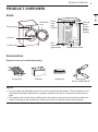
PRODUCT OVERVIEW
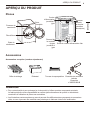
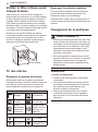
Parts
Control panel
Lint filter
Leveling feet
Reversible
door
Power
Cord
(gas
models)
Gas
connection
(gas models)
Exhaust Duct Outlet
Terminal
Block
Access
Panel
(electric
models)
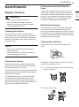
Accessories
Optional Accessories (Sold Separately)
Drying Rack Pedestal Stacking kit Side vent kit
Kit No. 383EEL9001B
NOTE
• For your safety and extended product life, use only authorized components. The manufacturer is not
responsible for product malfunction or accidents caused by the use of unauthorized components or
parts.
• The images in this manual may be different from the actual components and accessories which are
subject to change by the manufacturer without prior notice for product improvement purposes.

10
INSTALLATION
INSTALLATION
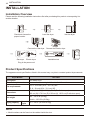
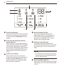
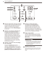
Installation Overview
Please read the following installation instructions first after purchasing this product or transporting it to
another location.
Check and choose the
proper location
Level the dryer Vent the dryer
Connect the Gas dryer Connect the Electric dryer
Gas dryer Installation test Test runElectric dryer
Plug in the power cord
Product Specifications
The appearance and specifications listed in this manual may vary due to constant product improvements.
Dryer Models DLE3400*
Description Non-steam Dryer
Electrical requirements Please refer to the rating label for detailed information.
Gas requirements
NG: 4 - 10.5-inch (10.2 - 26.7 cm) WC
LP: 8 - 13-inch (20.4 - 33.1 cm) WC
Dimensions
27” (W) X 30.2” (D) X 39” (H), 51.4” (D with door open)
68.6 cm (W) X 76.5 cm (D) X 99 cm (H), 130.5 cm (D with door open)
Net weight
Gas : 123.02 lb (55.8kg)
Electric : 120.15 lb (54.5kg)
Drying capacity
Normal
Cycle
IEC 7.4 cu.ft. (22.5 lb/10.2 kg)
NOTE
• Model numbers can be found on the cabinet inside the door.

11
INSTALLATION
ENGLISH
Installation Location Requirements
WARNING
• Read all installation instructions completely before installing and operating your dryer! It is important
that you review this entire manual before installing and using your dryer. Detailed instructions
concerning electrical connections, gas connections, and exhaust requirements are provided on the
following pages.
The installation requires:
• A location that allows for proper exhaust installation. A gas dryer must be exhausted to the outdoors.
See Venting the Dryer.
• A grounded electrical outlet located within 2 ft. (61 cm) of either side of the dryer. See Connecting
Electric Dryers.
• A sturdy floor to support the total dryer weight of 200 lb (90.7 kg). The combined weight of a companion
appliance should also be considered.
• No other fuel-burning appliance can be installed in the same closet as a dryer.
• Additional clearances might be required for wall, door and floor moldings.
• Companion appliance spacing should also be considered.
NOTE
• The floor must be level, with a maximum slope of 1 inch (2.5 cm) under the entire dryer. Clothes may
not tumble properly, and automatic sensor cycles may not operate correctly if the dryer is not level.
• For garage installation, you will need to place the dryer at least 18 inches (45.7 cm) above the floor.
The standard pedestal height is 15 inches (38 cm). You will need 18 inches (45.7 cm) from the garage
floor to the bottom of the dryer.
• Do not operate your dryer at temperatures below 45 °F (7 °C). At lower temperatures, the dryer might
not shut off at the end of an automatic cycle. This can result in longer drying times.
• The dryer must not be installed or stored in an area where it will be exposed to water and/or weather.
• Check code requirements that limit, or do not permit, installation of the dryer in garages, closets,
mobile homes or sleeping quarters. Contact your local building inspector.

12
INSTALLATION
Clearances
1"*
(25 mm)
14" max.*
(356 mm)
18" min.*
(457 mm)
14" max.*
(356 mm)
18" min.*
(457 mm)
30.2"
(765mm)
5"**
(127 mm)
1"*
(25 mm)
30.2"
(765mm)
5"**
(127 mm)
24 in.
2*
(
155 cm
2
)
2*
(310 cm
2
)
3"
*
(76 mm)
48 in.
3"
*
(76 mm)
1"
(25 mm)
1"
(25 mm)
27"
(686 mm)
0"
(0 mm)
39"
(990 mm)
1"
(25 mm)
1"
(25 mm)
27"
(686 mm)
Closet Door Vent
Requirements
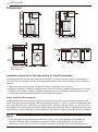
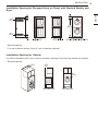
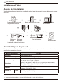
Installation Spacing for Recessed Area or Closet Installation
The following clearances are recommended for this dryer. This dryer has been tested for clearances of
1 inch (2.5 cm) on the sides and rear. Recommended clearances should be considered for the following
reasons:
• Additional clearances should be considered for ease of installation and servicing.
• Additional clearances should be considered on all sides of the dryer to reduce noise transfer. For closet
installation, with a door, minimum ventilation openings in the top and bottom of the door are required.
Louvered doors with equivalent ventilation openings are acceptable.
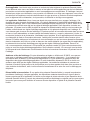
Closet Ventilation Requirements
Closets with doors must have both an upper and lower vent to prevent heat and moisture buildup in the
closet. One upper vent opening with a minimum opening of 48 sq. in. (310 cm
2
) must be installed no lower
than 6 feet above the floor. One lower vent opening with a minimum opening of 24 sq. in. (155 cm
2
) must
be installed no more than one foot above the floor. Install vent grills in the door or cut down the door at the
top and bottom to form openings. Louvered doors with equivalent ventilation openings are also acceptable.
NOTE
• There should be at least a little space around the dryer (or any other appliance) to eliminate the
transfer of vibration from one appliance to another. If there is enough vibration, it could cause
appliances to make noise or come into contact, causing paint damage and further increasing noise.

13
INSTALLATION
ENGLISH
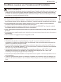
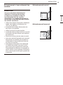
Installation Spacing for Recessed Area or Closet, with Stacked Washer and
Dryer
24 in.
2*
(155 cm
2
)
2*
(310 cm
2
)
48 in.
3"
*
(76 mm)
3"
*
(76 mm)
1"
*
(25 mm)
1"
(25 mm)
1"
(25 mm)
27"
(686 mm)
5 ½"
**
(140 mm)
6"
*
(152 mm)
77 ½"
(1968 mm)
* Required spacing
** For side or bottom venting, 2-inch (5.1 cm) of spacing is allowed.
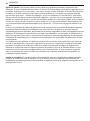
Installation Spacing for Cabinet
For cabinet installation with a door, minimum ventilation openings in the top of the cabinet are required.
* Required spacing
7" *
(178 mm)
7" *
(178 mm)
9" *
1"
(25 mm)
1"
(25 mm)
27"
(686 mm)
5"*
(127 mm)
1"*
(25 mm)
30.2"
(765 mm)
(229 mm)

14
INSTALLATION
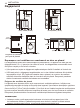
Leveling the Dryer
WARNING
• Use long-sleeved gloves and safety glasses.
• The appliance is heavy. Two or more people
are required when installing the dryer.
NOTE
• Adjust the leveling feet only as far as
necessary to level the dryer. Extending the
leveling feet more than necessary may cause
the dryer to vibrate.
• To ensure that the dryer provides optimal
drying performance, it must be level. To
minimize vibration, noise, and unwanted
movement, the floor must be a perfectly level,
solid surface.
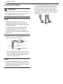
1
Position the dryer in the final location. Place a
level across the top of the dryer.
Level
Leveling Feet
• All four leveling feet must rest solidly on the
floor. Gently push on the top corners of the
dryer to make sure that the dryer does not
rock from corner to corner.
NOTE
• If you are installing the dryer on the optional
pedestal, you must use the leveling feet on the
pedestal to level the dryer. The dryer leveling
feet should be fully retracted.
2
Use an adjustable wrench to turn the leveling
feet. Unscrew the legs to raise the dryer or
screw in the legs to lower it. Raise or lower
with the leveling feet until the dryer is level
from side to side and front to back. Make sure
that all four leveling feet are in firm contact
with the floor.

15
INSTALLATION
ENGLISH
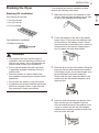
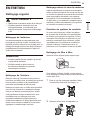
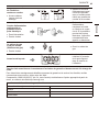
Reversing the Door
Tools Required
• Phillips screwdriver
• Large flat blade screwdriver (recommended for
hinge screws if they are tight or your Phillips
screwdriver is worn)
• Small flat blade screwdriver (for lifting out parts)
WARNING
• Support the door with a stool or box that fits
under the door, or have an assistant support
the weight of the door.
• Avoid dropping the door.
• Unplug the dryer or turn off power at the main
circuit breaker before beginning door reversal.
• Always reverse the door BEFORE stacking
the dryer on top of the washer.
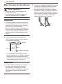
Door Reversal Instructions
The instructions here are for changing the door
swing from a right to a left side hinge. If the
door has been reversed, and it is necessary to
change it back, use care when following these
instructions. Some of the illustrations and the left/
right references will be reversed, and you will need
to read the instructions carefully.
WARNING
• Be sure to support the weight of the door
before removing the hinge screws.
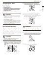
1
Open the door and remove the two decorative
screws, two latch screws, and the latch on the
catch side with a screwdriver. Save these for
step 4.
2
While supporting the door, remove the 2
screws on the door hinge. Remove the door.
3
Turn the door upside down and line up the
holes in the hinge with the holes on the
opposite side of the cabinet. Reinstall the door
with the screws removed in step 2.
WARNING
• Be sure to support the weight of the door
before installing the hinge screws.
4
Install the two decorative screws, the latch,
and two latch screws removed in step 1 on the
opposite side from which they were removed.
5
Check that the door closes properly.

16
INSTALLATION
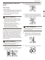
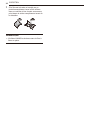
Installing the Side Vent Kit
WARNING
• Use long-sleeved gloves and safety glasses.
• Use a heavy metal vent.
• Do not use plastic or thin foil ducts.
• Clean old ducts before installing this dryer.
Your new dryer is configured to vent to the rear.
It can also vent to the bottom or side (right-side
venting is not available on gas models).
An adapter kit, part number 383EEL9001B, may
be purchased from your LG retailer. This kit
contains duct components necessary to change
the dryer vent location.
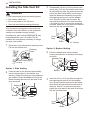
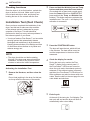
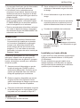
1
Remove the rear exhaust duct retaining screw.
Pull out the exhaust duct.
Retaining
Screw
Rear Exhaust Duct
Option 1: Side Venting
2
Press the tabs on the knockout and carefully
remove the knockout for the desired vent
opening. (Right-side venting is not available on
gas models.) Press the adapter duct onto the
blower housing and secure to the base of the
dryer as shown.
Adapter Duct
Bracket
Knockout
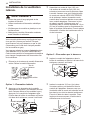
3
Preassemble a 4-inch (10.2 cm) elbow to the
next 4-inch (10.2 cm) duct section, and secure
all joints with duct tape. Be sure that the male
end of the elbow faces AWAY from the dryer.
Insert the elbow/duct assembly through the
side opening and press it onto the adapter
duct. Secure it in place with duct tape. Be
sure that the male end of the duct protrudes
1.5 inches (3.8 cm) to connect the remaining
ductwork. Attach the cover plate to the back of
the dryer with the included screw.
Cover
Plate
Elbow
1½” (38 mm)
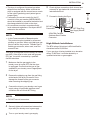
Option 2: Bottom Venting
2
Press the adapter duct onto the blower
housing and secure it to the base of the dryer
as shown.
Adapter Duct
Bracket
3
Insert the 4-inch (10.2 cm) elbow through the
rear opening and press it onto the adapter
duct. Be sure that the male end of the elbow
faces down through the hole in the bottom of
the dryer. Secure it in place with duct tape.
Attach the cover plate to the back of the dryer
with the included screw.
Cover
Plate
Elbow

17
INSTALLATION
ENGLISH
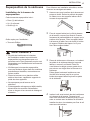
Stacking the Dryer
Stacking Kit Installation
This stacking kit includes:
• Two (2) side rails
• One (1) front rail
• Four (4) screws
Tools Needed for Installation:
• Phillips screwdriver
WARNING
• The weight of the dryer and the height of
installation make this stacking procedure too
risky for one person. Two or more people are
required when installing the stacking kit.
• Do not use the stacking kit with a gas dryer
in potentially unstable conditions such as a
mobile home.
• Place the washer on a solid, stable, level
floor capable of supporting the weight of both
appliances.
• Do not stack the washer on top of the dryer.
• If appliances are already installed, disconnect
them from all power, water, or gas lines and
from draining or venting connections.
To ensure safe and secure installation, please
observe the following instructions.
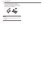
1
Make sure the surface of the washer is clean
and dry. Remove paper backing from the tape
on one of the stacking kit side brackets.
2
Fit the side bracket to the side of the washer
top as shown. Firmly press the adhesive area
of the bracket to the washer surface. Secure
the side bracket to the washer with a screw on
the back side of the bracket. Repeat steps 1
and 2 to attach the other side bracket.
3
Place the dryer on top of the washer, fitting the
dryer feet into the side brackets as illustrated.
Avoid finger injuries; do not allow fingers to be
pinched between the washer and dryer.
Slowly slide the dryer toward the back of the
washer until the side bracket stoppers catch
the dryer feet.
4
Insert the front rail between the bottom of the
dryer and the top of the washer. Push the
front rail toward the back of the washer until it
comes in contact with the side rail stoppers.
Install the two remaining screws to secure the
front rail to the side rails.

18
INSTALLATION
Venting the Dryer
WARNING
• Do not crush or collapse ductwork.
• Do not allow ductwork to rest on or contact
sharp objects.
• If connecting to existing ductwork, make sure
it is suitable and clean before installing the
dryer.
• Venting must conform to local building codes.
• Gas dryers MUST exhaust to the outdoors.
• Use only 4-inch (10.2 cm) rigid, semi-rigid
or flexible metal ductwork inside the dryer
cabinet and for venting outside.
• To reduce the risk of fire, combustion, or
accumulation of combustible gases, DO
NOT exhaust dryer air into an enclosed and
unventilated area, such as an attic, wall,
ceiling, crawl space, chimney, gas vent, or
concealed space of a building.
• To reduce the risk of fire, DO NOT exhaust the
dryer with plastic or thin foil ducting.
• The exhaust duct must be 4 inches (10.2 cm)
in diameter with no obstructions. The exhaust
duct should be kept as short as possible.
Make sure to clean any old ducts before
installing your new dryer.
• Rigid, semi-rigid or flexible metal ducting is
recommended for use between the dryer and
the wall. All non-rigid metal transition duct
must be UL-listed. Use of other materials for
transition duct could affect drying time.
• DO NOT use sheet metal screws or other
fasteners which extend into the duct that could
catch lint and reduce the efficiency of the
exhaust system. Secure all joints with duct
tape.
• Do not exceed the recommended duct length
limitations noted in the chart. Failure to follow
these instructions may result in extended
drying times, fire or death.
WARNING
• Ductwork is not provided with the dryer. You
should obtain the necessary ductwork locally.
The vent hood should have hinged dampers to
prevent backdraft when the dryer is not in use.
• The total length of flexible metal duct must not
exceed 8 ft. (2.4 m).
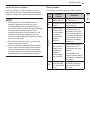
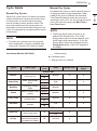
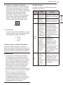
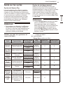
Ductwork
Wall Cap Type
Number
of 90°
Elbows
Maximum
length of 4-inch
diameter rigid
metal duct
Recommended
a
a
a: 4” (10.2 cm)
0 65 ft.(19.8 m)
1 55 ft.(16.8 m)
2 47 ft.(14.3 m)
3 36 ft.(11.0 m)
4 28 ft.(8.5 m)
Use only for short
run installations
b
b: 2.5” (6.35 cm)
0 55 ft.(16.8 m)
1 47 ft.(14.3 m)
2 41 ft.(12.5 m)
3 30 ft.(9.1 m)
4 22 ft.(6.7 m)
NOTE
• Deduct 6 ft. (1.8 m) for each additional elbow.
Do not use more than four 90° elbows.
• In Canada, only those foil-type flexible ducts,
if any, specifically identified for use with the
appliance by the manufacturer should be
used. In the United States, only those foil-type
flexible ducts, if any, specifically identified for
use with the appliance by the manufacturer
and that comply with the Outline for Clothes
Dryer Transition Duct, Subject 2158A, should
be used.

19
INSTALLATION
ENGLISH
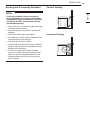
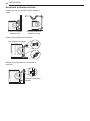
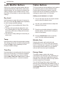
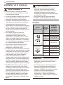
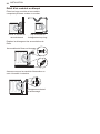
Routing and Connecting Ductwork
NOTE
Follow the guidelines below to maximize
drying performance and reduce lint buildup
and condensation in the ductwork. Ductwork
and fittings are NOT included and must be
purchased separately.
• Use 4-inch (10.2 cm) diameter rigid, semi-rigid
or flexible metal ductwork.
• The exhaust duct run should be as short as
possible.
• Use as few elbow joints as possible.
• The male end of each section of exhaust duct
must point away from the dryer.
• Use duct tape on all duct joints.
• Insulate ductwork that runs through unheated
areas in order to reduce condensation and lint
buildup on duct surfaces.
• Incorrect or inadequate exhaust systems
are not covered by the dryer warranty. Dryer
failures or service required because of such
exhaust systems will not be covered by the
dryer warranty.
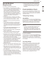
Correct Venting
Incorrect Venting

20
INSTALLATION
Connecting Gas Dryers
WARNING
To reduce the risk of fire or explosion,
electric shock, property damage, injury to
persons, or death when using this appliance,
follow requirements including the following:
Electrical Requirements for Gas
Models Only
• Do not, under any circumstances, cut or remove
the third (ground) prong from the power cord.
• For personal safety, this dryer must be properly
grounded.
• This dryer must be plugged into a 120-VAC, 60-
Hz. grounded outlet protected by a 15-ampere
fuse or circuit breaker.
ELECTRIC SHOCK HAZARD
Failure to follow safety warnings could result
in serious injury
• This dryer is equipped with a three-prong
grounding plug for protection against shock
hazard and should be plugged directly into a
properly grounded three-prong receptacle. Do
not cut or remove the grounding prong from this
plug.
• Where a standard 2-prong wall outlet is
encountered, it is your personal responsibility
and obligation to have it replaced with a properly
grounded 3-prong wall outlet.
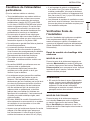
Gas Supply Requirements
• As shipped from the factory, this dryer is
configured for use with natural gas (NG). It can
be converted for use with propane (LP) gas.
Gas pressure must not exceed 8-inch (20.4 cm)
water column for NG, or 13-inch (33.1 cm) water
column for LP.
• A qualified service or gas company technician
must connect the dryer to the gas service.
• Isolate the dryer from the gas supply system by
closing its individual manual shutoff valve during
any pressure testing of the gas supply.
• Supply line requirements: Your laundry room
must have a rigid gas supply line to your dryer.
In the United States, an individual manual
shutoff valve MUST be installed within at least
6 ft. (1.8 m) of the dryer, in accordance with
the National Fuel Gas Code ANSI Z223.1 or
Canadian gas installation code CSA B149.1. A
1/8-inch NPT pipe plug must be installed.
• If using a rigid pipe, the rigid pipe should be
0.5-inch IPS. If acceptable under local codes
and ordinances and when acceptable to your
gas supplier, 3/8-inch approved tubing may be
used where lengths are less than 20 ft. (6.1
m). Larger tubing should be used for lengths in
excess of 20 ft. (6.1 m).
• To prevent contamination of the gas valve,
purge the gas supply of air and sediment before
connecting the gas supply to the dryer. Before
tightening the connection between the gas
supply and the dryer, purge remaining air until
the odor of gas is detected.
• DO NOT use an open flame to inspect for gas
leaks. Use a noncorrosive leak detection fluid.
• Use only a new AGA- or CSA-certified
gas supply line with flexible stainless steel
connectors.
• Use Teflon tape or a pipe-joint compound that
is insoluble in propane (LP) gas on all pipe
threads.
WARNING
• DO NOT attempt any disassembly of the
dryer; disassembly requires the attention and
tools of an authorized and qualified service
technician or company.
• Securely tighten all gas connections.
• Connect the dryer to the type of gas shown on
the nameplate.
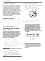
Connecting the Gas Supply
• Installation and service must be performed by
a qualified installer, service agency, or the gas
supplier.
• Use only a new stainless steel flexible connector
and a new AGA-certified connector.
• A gas shutoff valve must be installed within 6 ft.
(1.8 m) of the dryer.
La page est en cours de chargement...
La page est en cours de chargement...
La page est en cours de chargement...
La page est en cours de chargement...
La page est en cours de chargement...
La page est en cours de chargement...
La page est en cours de chargement...
La page est en cours de chargement...
La page est en cours de chargement...
La page est en cours de chargement...
La page est en cours de chargement...
La page est en cours de chargement...
La page est en cours de chargement...
La page est en cours de chargement...
La page est en cours de chargement...
La page est en cours de chargement...
La page est en cours de chargement...
La page est en cours de chargement...
La page est en cours de chargement...
La page est en cours de chargement...
La page est en cours de chargement...
La page est en cours de chargement...
La page est en cours de chargement...
La page est en cours de chargement...
La page est en cours de chargement...
La page est en cours de chargement...
La page est en cours de chargement...
La page est en cours de chargement...
La page est en cours de chargement...
La page est en cours de chargement...
La page est en cours de chargement...
La page est en cours de chargement...
La page est en cours de chargement...
La page est en cours de chargement...
La page est en cours de chargement...
La page est en cours de chargement...
La page est en cours de chargement...
La page est en cours de chargement...
La page est en cours de chargement...
La page est en cours de chargement...
La page est en cours de chargement...
La page est en cours de chargement...
La page est en cours de chargement...
La page est en cours de chargement...
La page est en cours de chargement...
La page est en cours de chargement...
La page est en cours de chargement...
La page est en cours de chargement...
La page est en cours de chargement...
La page est en cours de chargement...
La page est en cours de chargement...
La page est en cours de chargement...
La page est en cours de chargement...
La page est en cours de chargement...
La page est en cours de chargement...
La page est en cours de chargement...
La page est en cours de chargement...
La page est en cours de chargement...
La page est en cours de chargement...
La page est en cours de chargement...
La page est en cours de chargement...
La page est en cours de chargement...
La page est en cours de chargement...
La page est en cours de chargement...
La page est en cours de chargement...
La page est en cours de chargement...
La page est en cours de chargement...
La page est en cours de chargement...
La page est en cours de chargement...
La page est en cours de chargement...
La page est en cours de chargement...
La page est en cours de chargement...
La page est en cours de chargement...
La page est en cours de chargement...
La page est en cours de chargement...
La page est en cours de chargement...
La page est en cours de chargement...
La page est en cours de chargement...
La page est en cours de chargement...
La page est en cours de chargement...
-
 1
1
-
 2
2
-
 3
3
-
 4
4
-
 5
5
-
 6
6
-
 7
7
-
 8
8
-
 9
9
-
 10
10
-
 11
11
-
 12
12
-
 13
13
-
 14
14
-
 15
15
-
 16
16
-
 17
17
-
 18
18
-
 19
19
-
 20
20
-
 21
21
-
 22
22
-
 23
23
-
 24
24
-
 25
25
-
 26
26
-
 27
27
-
 28
28
-
 29
29
-
 30
30
-
 31
31
-
 32
32
-
 33
33
-
 34
34
-
 35
35
-
 36
36
-
 37
37
-
 38
38
-
 39
39
-
 40
40
-
 41
41
-
 42
42
-
 43
43
-
 44
44
-
 45
45
-
 46
46
-
 47
47
-
 48
48
-
 49
49
-
 50
50
-
 51
51
-
 52
52
-
 53
53
-
 54
54
-
 55
55
-
 56
56
-
 57
57
-
 58
58
-
 59
59
-
 60
60
-
 61
61
-
 62
62
-
 63
63
-
 64
64
-
 65
65
-
 66
66
-
 67
67
-
 68
68
-
 69
69
-
 70
70
-
 71
71
-
 72
72
-
 73
73
-
 74
74
-
 75
75
-
 76
76
-
 77
77
-
 78
78
-
 79
79
-
 80
80
-
 81
81
-
 82
82
-
 83
83
-
 84
84
-
 85
85
-
 86
86
-
 87
87
-
 88
88
-
 89
89
-
 90
90
-
 91
91
-
 92
92
-
 93
93
-
 94
94
-
 95
95
-
 96
96
-
 97
97
-
 98
98
-
 99
99
-
 100
100


LG DLE3400W Le manuel du propriétaire
- Catégorie
- Sèche-linge
- Taper
- Le manuel du propriétaire
dans d''autres langues
- English: LG DLE3400W Owner's manual
Documents connexes
-
LG DLE3095W Le manuel du propriétaire
-
LG DLGX3901B Le manuel du propriétaire
-
LG DLG3051W Le manuel du propriétaire
-
LG DLE1501W Le manuel du propriétaire
-
LG DLE1001W Le manuel du propriétaire
-
LG DLE2250W Le manuel du propriétaire
-
LG DLEX7600VE Le manuel du propriétaire
-
LG DLEX2650T Le manuel du propriétaire
-
LG DLEX3250R Le manuel du propriétaire
-
LG DLE6100W Le manuel du propriétaire