Simplicity 01021-0 Le manuel du propriétaire
- Catégorie
- Groupes électrogènes
- Taper
- Le manuel du propriétaire
Ce manuel convient également à

Model No. 1021-0 (6500 Watt AC Generator) Manual No. B1479 Revision 3 (3/14/2000)
Modèle No 1021-0 (Générateur c.a. de 6500 watts) Manuel No B1479 Révision 3 (14 Mars 2000)
Visit our Generac website: www.generac-portables.com
Visiter notre Generac website: www.generac-portables.com
Problems?
Questions?
Before taking your
unit back to the store,
call the generator
helpline at
18002701408
MF 85 CT
MEGAFORCE 6500
GENERAC
The Reliable Ones
™
Safety
Assembly
Operation
Maintenance
Parts
French
Sûreté
Assemblée
Opération
Entretien
Parties
Français
Les problèmes?
Les questions?
Avant de prendre votre
dos d'unité au magasin,
appeler le helpline de
générateur à
18002701408
MF 85 CT
Extended Life Generator Owner’s Manual
Manuel de l’Utilisateur pour le Générateur à Durée de vie Prolongée

MEGAFORCE 6500 Extended Life Generator
2
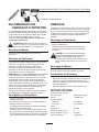
EQUIPMENT DESCRIPTION
This generator is an enginedriven, revolving field,
alternating current (AC) generator. It was designed to
supply electrical power for operating compatible
electrical lighting, appliances, tools and motor loads.
This manual contains information for a generator that
operates 120 and/or 240 Volt AC, single phase, 60 Hz
devices that require up to 6500 watts (6.5 kW) of
power that pull up to 54.1 Amps at 120 Volts or
27 Amps at 240 Volts.
The Emission Control System for this generator is
warranted for standards set by the Environmental
Protection Agency. For warranty information refer to
the engine owners manual.
SAFETY RULES
This generator set was designed and manufactured for
specific applications. Do Not attempt to modify the
unit or use it for any application it was not designed
for. If you have any questions about your generators
application, ask your dealer or consult the factory.
The manufacturer could not possibly anticipate every
circumstance that might involve a hazard. For that
reason warnings in the manual and warnings on tags
or decals affixed to the unit are not allinclusive. If you
intend to handle, operate or service the unit by a
procedure or method not specifically recommended by
the manufacturer, first make sure that such a
procedure or method will not render this equipment
unsafe or pose a threat to you and others.
Read this manual carefully and become familiar
with your generator set. Know its applications, its
limitations and any hazards involved.
DANGER! This generator is designed for
outdoor use only. Never use this generator
inside any building or enclosure including the
generator compartment of a recreational vehicle
(RV). Carbon monoxide poisoning, fire
and/or an explosion may result. No user
performed modifications, including venting of
exhaust and/or cooling ventilation, will eliminate
the danger. Always have at least two feet of
clearance on all sides of the generator while
operating the unit.
DANGER! You must isolate the generator
from the electric utility using approved transfer
equipment if this unit is used for backup power.
Failure to isolate the generator from the
power utility may result in injury or death to
electric utility workers and damage to the
generator due to a backfeed of electrical
energy. Whenever unit is providing backup
power, the electric utility must be notified.
DANGER! Do Not tamper with engine
governed speed. High operating speeds are
dangerous and increase risk of personal injury
or damage to equipment. The generator
supplies correct rated frequency and voltage
only when running at proper governed speed.
Incorrect frequency and/or voltage can damage
some connected electrical loads. Operating at
excessively low speeds imposes a heavy load.
When adequate engine power is not available
engine life may be shortened.
DANGER! Do Not exceed the generators
wattage/amperage capacity. Add up the rated
watts of all devices you are connecting to
generator receptacles at one time. This total
should not be greater than 6,500 watts for this
generator. See Do Not Overload the
Generator on page 12 for specific information.
This is the safety alert symbol. It is used to alert you to potential personal injury hazards.
Obey all safety messages that follow this symbol to avoid possible injury or death.
The engine exhaust from this product contains
chemicals known to the State of California to
cause cancer, birth defects, or other
reproductive harm.
WARNING:

MEGAFORCE 6500 Extended Life Generator
3
The generator produces a very powerful voltage that
can cause serious injury or death by electrocution.
Never touch bare wires or receptacles. Never permit
a child or any unqualified person to operate the
generator.
Never handle any kind of electrical cord or device
while standing in water, while barefoot or while
hands or feet are wet.
Use a ground fault circuit interrupter (GFCI) in any
damp or highly conductive area (such as metal
decking or steel work).
Never use worn, bare, frayed or otherwise damaged
electrical cords with the generator.
Gasoline is highly FLAMMABLE and its vapors
are EXPLOSIVE. Never allow smoking, open
flames, sparks or heat in the vicinity while
handling gasoline. Avoid spilling gasoline on a
hot engine. Comply with all laws regulating storage
and handling of gasoline.
Do Not overfill the fuel tank. Always allow room for
fuel expansion. If tank is overfilled, fuel can overflow
onto a hot engine and cause a FIRE or an
EXPLOSION.
Never store a generator with fuel in the tank where
gasoline vapors might reach an open flame, spark or
pilot light (as on a furnace, water heater, clothes
dryer). FIRE or an EXPLOSION may result.
The unit requires an adequate flow of cooling air for
its continued proper operation. Never operate the
unit inside any room or enclosure where the free
flow of cooling air into and out of the unit might be
obstructed. Allow at least 2 feet of clearance on all
sides of generator or you could damage the unit.
Read Cold Weather Operation on page 9.
Never start or stop the unit with electrical loads
connected to receptacles AND with the connected
devices turned ON. Start the engine and let it
stabilize before connecting any electrical loads.
Disconnect all electrical loads before shutting down
the generator.
Do Not insert any object through the units cooling
slots or damage to you or the unit could happen.
Never operate the generator:
in rain; in any enclosed compartment; when
connected electrical devices overheat; if electrical
output is lost; if engine or generator sparks; if flame
or smoke is observed while unit is running; if unit
vibrates excessively.
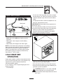
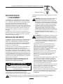
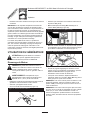
GROUNDING THE
GENERATOR
The National Electrical Code requires that the frame
and external electrically conductive parts of this
generator be properly connected to an approved earth
ground. Local electrical codes may also require proper
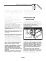
grounding of the unit. For that purpose, a
GROUNDING WING NUT is provided on the
generator end (Figure 1).
Generally, connecting a No. 12 AWG (American Wire
Gauge) stranded copper wire to the grounding wing
nut and to an earthdriven copper or brass grounding
rod (electrode) provides adequate protection against
electrical shock. Be careful to keep the grounding wire
attached after connecting the stranded copper wire.
However, local codes may vary widely. Consult with a
local electrician for grounding requirements in your
area.
Properly grounding the generator helps prevent
electrical shock if a ground fault condition exists in the
generator or in connected electrical devices. Proper
grounding also helps dissipate static electricity, which
often builds up in ungrounded devices.
Grounding Wing Nut
Figure 1 Grounding Wing Nut

MEGAFORCE 6500 Extended Life Generator
4
12 Volt DC,10 Amp Receptacle Recharge a
discharged 12 Volt automotive type battery through
this receptacle.
120 Volt AC, 15 Amp GFCI Receptacle May be
used to supply electrical power for the operation of
120 Volt AC, 15 Amp, single phase, 60 Hz electrical
lighting, appliance, tool and motor loads.
120 Volt AC, 30 Amp Locking Receptacle May be
used to supply electrical power for the operation of
120 Volt AC, 30 Amp, single phase, 60 Hz electrical
lighting, appliance, tool and motor loads.
120/240 Volt AC, 30 Amp Locking Receptacle
May be used to supply electrical power for the
operation of 120 and/or 240 Volt AC, 30 Amp, single
phase, 60 Hz electrical lighting, appliance, tool and
motor loads.
Air Cleaner Uses a dry type filter element and
foam precleaner to limit dirt and dust intake.
Choke Lever Used when starting a cold engine.
Circuit Breakers (AC) Each receptacle is provided
with a "push to reset" circuit breaker to protect the
generator against electrical overload.
Fuel Tank Capacity of seven (7) U.S. gallons.
Grounding Wing Nut Used for grounding of unit.
Hour Meter Used to schedule preventative
maintenance tasks.
Idle Control Switch With this switch set to ON,
printed circuit board in control panel automatically
reduces engine speed when no load is connected and
increases engine to proper speed when load is
applied. However, be sure switch is OFF when starting
engine.
Recoil starter Used to start the engine.
Run/Stop Switch Set this switch to "Run" before
using recoil starter. Set switch to "Stop" to switch OFF
engine.
Spark Arrestor Muffler Exhaust muffler lowers
engine noise, equipped with a spark arrestor screen.
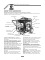
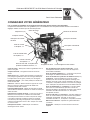
KNOW YOUR GENERATOR
Read this owners manual and safety rules before operating your generator.
Compare the illustrations with your generator, to familiarize yourself with the locations of various controls and
adjustments. Save this manual for future reference.
120 Volt AC, 15 Amp
GFCI Receptacle
Hour Meter
Fuel Tank
Idle Control Switch
Choke Lever
Recoil Starter
12 Volt DC, 10 Amp
Receptacle
Run/Stop Switch
120 Volt AC,
30 Amp Receptacle
Circuit Breakers
120/240 Volt AC,
30 Amp Receptacle
Spark Arrestor Muffler
Air Cleaner
Grounding Wing Nut

MEGAFORCE 6500 Extended Life Generator
5
Your generator requires some assembly and is ready
for use after it has been properly serviced with the
recommended oil and fuel.
If you have any problems with the assembly of your
generator, please call the generator helpline at
1-800-270-1408.
IMPORTANT: Any attempt to run the unit before it has
been serviced with the recommended oil will result in
an engine failure.
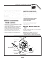
REMOVE GENERATOR
FROM CARTON
Set the carton on a rigid flat surface with This Side
Up arrows pointing upward.
Carefully open the top flaps of the shipping carton.
Review Cold Weather Operation on page 9.
Cut down corners at one end of carton from top to
bottom and lay that side of carton down flat.
Remove all packing material, carton fillers, etc.
Remove the generator from the shipping carton.
CARTON CONTENTS
Check all contents. If any parts are missing or
damaged, call the generator helpline at
1-800-270-1408.
The generator
Wheel and lift kit
Generator and engine owners manuals
Locking 20 Amp and 30 Amp plugs
Battery charge cables
Battery tray mounting bracket/hardware
Spare spark plug and air filter element
Spark plug wrench
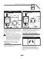
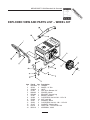
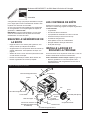
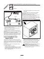
INSTALL WHEEL AND LIFT
KIT
You need a socket wrench with 1/2" or 13mm sockets
to assemble wheel/lift kit.
Install Wheel Kit as follows: (See Figure 2)
Place the generator on a hard flat surface.
Temporarily raise unit on blocks to ease assembly.
Lift Bar
45mm Capscrew
45mm Capscrew
Flat Washer
20mm
Capscrew
Flat Washer
Lock Nut
Lock Nut
Lock
Nut
30mm Capscrew
Vibration Mount
Support Leg
Wheel
Spacer
Retaining Pin
Axle
Wheel
Handle
Figure 2 Assemble Wheel Kit
Lock
Nut

MEGAFORCE 6500 Extended Life Generator
6
Slide the axle through the holes in the brackets
provided on the generator cradle and then add the
two spacers on each protruding end of the axle.
Slide a wheel on each end of the axle and secure
each with washer and retaining pin.
NOTE: Install the wheels with the air inflation valve
facing outward.
Attach the vibration mounts to the support leg with
capscrews, washers and lock nuts.
Attach the support leg to the cradle with capscrews
and lock nuts. Remove the temporary blocks.
Attach the handle to the units control panel end with
four cap screws and four lock nuts.
Check that all fasteners are tight.
Follow these instructions precisely to ensure proper
center of gravity for crane or hoist lifting. Referring to
Figure 3, install as follows:
Place the lift bar on top of the cradle making sure,
as you look at the bar from the control panel side,
that it forms a reverse L.
Make sure the lift bar is 9 1/4" from the outside of
the cradle on the right side to the base of the lift bar
bracket.
Attach the lift bar to the cradle using four cap screws
and four lock nuts.
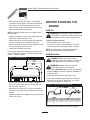
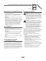
BEFORE STARTING THE
ENGINE
Add Oil
WARNING! Any attempt to crank or start the
engine before it has been properly filled with the
recommended oil may result in engine failure.
To fill your engine with oil:
Place generator on a level surface.
Follow the oil grade recommendations and oil fill
instructions given in the engine owners manual.
NOTE: The generators revolving field rides on a
permanent prelubricated sealed ball bearing.
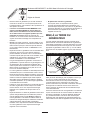
Add Gasoline
DANGER! NEVER fill fuel tank indoors.
NEVER fill fuel tank when engine is running or
hot. Do Not smoke when filling the fuel tank.
WARNING! Do Not overfill the fuel tank.
Always allow room for fuel expansion.
Use regular UNLEADED gasoline with the generator
engine. Do Not use premium gasoline. Do Not mix
oil with gasoline.
Clean area around fuel fill cap, remove cap.
Slowly add unleaded regular gasoline to fuel tank.
Be careful not to overfill. Allow about 1/2" of tank
space for fuel expansion (Figure 4).
Install fuel cap and wipe up any spilled gasoline.
Figure 3 Assemble Lift Kit
Figure 4 Typical Fuel Expansion Space

MEGAFORCE 6500 Extended Life Generator
7
IMPORTANT: It is important to prevent gum deposits
from forming in essential fuel system parts, such as
the carburetor, fuel filter, fuel hose or tank during
storage. Also, experience indicates that
alcoholblended fuels (called gasohol, ethanol or
methanol) can attract moisture, which leads to
separation and formation of acids during storage.
Acidic gas can damage the fuel system of an engine
while in storage.
To avoid engine problems, the fuel system should be
emptied before storage of 30 days or longer. See
Storage on page 13. Never use engine or carburetor
cleaner products in the fuel tank or permanent
damage may occur.
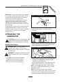
OPERATING THE
GENERATOR
CAUTION! Never start or stop the engine with
electrical loads connected to the receptacles
AND with the connected devices turned ON.
Starting the Engine
DANGER! Never run engine indoors or in
enclosed poorly ventilated areas. Engine
exhaust contains carbon monoxide, an odorless
and deadly gas.
WARNING! Temperature of muffler and nearby
areas may exceed 150°F (65°C). Avoid these
areas.
Unplug all electrical loads from generator
receptacles before starting the engine.
Make sure the unit is in a level position.
Open the fuel shutoff valve (Figure 5).
Make sure the Idle Control switch is Off.
Place Run/Stop switch in the Run position
(Figure 6).
Place the choke lever in the Full choke position by
sliding it to the left in the direction indicated by the
arrow molded into the cover (Figure 7).
Grasp starter grip and pull slowly until you feel slight
resistance, then pull quickly. Do Not let handle
snap-back into recoil housing.
When engine starts, slowly move choke lever to the
Run position (to the right) as the engine warms.
NOTE: If engine fails to start after 3 pulls, move the
choke lever to Half choke position and pull starter
rope again 2 times.
NOTE: If the engine still fails to start, review the
engine owners manual. Also, check for proper oil level
in crankcase. Unit is equipped with a low oil shutdown
system, as described in the engine owners manual.
Figure 6 Run/Stop Switch
Figure 5 Fuel Shut-off Valve
Figure 7 Choke Lever

MEGAFORCE 6500 Extended Life Generator
8
Connecting Electrical Loads
Let engine stabilize and warm up for three minutes
after starting.
Plug in and turn on the desired 120 and/or 240 Volt
AC, single phase, 60 Hz electrical loads.
Do Not connect 240 Volt loads to the 120 Volt
receptacles.
Do Not connect 3phase loads to the generator.
Do Not connect 50 Hz loads to the generator.
DO NOT OVERLOAD THE GENERATOR. Add up
the rated watts (or amps) of all loads to be run at
one time. This total should not be greater than the
rated wattage/amperage capacity of the generator.
See Dont Overload the Generator on page 12.
Stopping the Engine
Unplug all electrical loads from generator panel
receptacles. Never start or stop engine with
electrical devices plugged in and turned on.
Put the idle control switch in the Off position.
Let engine run at noload for three minutes to
stabilize the units internal temperatures.
Move run/stop switch to Stop.
Close the fuel shutoff valve.
Operating Automatic Idle Control
This switch is designed to greatly improve fuel
economy. When this switch is turned ON, the engine
will only run at its normal high governed engine speed
when an electrical load is connected. When the load is
removed, the engine will run at a reduced speed. With
the switch Off, the engine runs constantly at the
normal high engine speed. Always have the switch
Off when starting and stopping the engine.
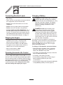
Charging a Battery
DANGER! Storage batteries give off explosive
hydrogen gas while recharging. An explosive
mixture will remain around the battery for a long
time after it has been charged. The slightest
spark can ignite the hydrogen and cause an
explosion, resulting in blindness or other
serious injury.
DANGER! Do Not permit smoking, open
flame, sparks or any other source of heat
around a battery. Wear protective goggles,
rubber apron and rubber gloves when working
around a battery. Battery electrolyte fluid is an
extremely caustic sulfuric acid solution that can
cause severe burns. If a spill occurs, flush area
with clear water immediately.
Your generator has the capability of recharging a
discharged 12 Volt automotive or utility style storage
battery. Do Not use the unit to charge any 6 Volt
batteries. Do Not use the unit to crank an engine
having a discharged battery.
To recharge 12 Volt batteries, proceed as follows:
Check fluid level in all battery cells. If necessary,
add ONLY distilled water to cover separators in
battery cells. Do Not use tap water.
If the battery is equipped with vent caps, make sure
they are installed and are tight.
If necessary, clean battery terminals.
Connect battery charge cable connector plug to
panel receptacle identified by the words
12 VOLTS D.C..
Connect battery charge cable clamp with red handle
to the positive (+) battery terminal (Figure 8).

MEGAFORCE 6500 Extended Life Generator
9
Connect battery charge cable clamp connected to
black lead to the negative () battery terminal
(Figure 8).
Start engine. Let the engine run while battery
recharges.
When battery has charged, shut down engine
NOTE: Use an automotive hydrometer to test battery
state of charge and condition. Follow the hydrometer
manufacturers instructions carefully. Generally, a
battery is considered to be at 100% state of charge
when specific gravity of its fluid (as measured by
hydrometer) is 1.260 or higher.
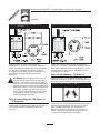
COLD WEATHER
OPERATION
Under certain weather conditions (temperatures below
40°F [4°C] and a high dew point), your generator may
experience icing of the carburetor and/or the
crankcase breather system.
In an emergency, use the original shipping box as a
temporary shelter:
Cut off all flaps.
Cut out one of the long sides of the box to expose
exhaust side of unit. Ensure a minimum of two feet
clearance between open side of box and nearest
object.
Cut appropriate slots to access receptacles of unit.
Start unit, then place box over it.
IMPORTANT! Remove shelter when temperature is
above 40°F [4°C].
For a more permanent shelter, build a structure that
will enclose three sides and the top of the generator:
Make sure entire muffler-side of generator is
exposed. Note that your generator may appear
different from that shown in Figure 9.
Ensure a minimum of two feet clearance between
open side of box and nearest object.
Face exposed end away from wind and elements.
Enclosure should hold enough heat created by the
generator to prevent problems.
CAUTION! NEVER run unit indoors. Do Not
enclose generator any more than shown.
Remove shelter when temperatures are above
40°F [4°C].
Figure 8 Battery Connections
Black lead
Wind
Figure 9 Temporary Cold Weather Shelter

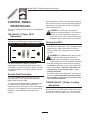
CONTROL PANEL/
RECEPTACLES
This unit is equipped wit the following receptacles and
controls:
120 Volt AC, 15 Amp, GFCI
Receptacle
Each receptacle (Figure 10) is protected against
overload by a 15 Amp pushtoreset circuit breaker.
Use each receptacle to operate 120 Volt AC,
singlephase, 60 Hz electrical loads requiring up to
1,800 watts (1.8 kW) at 15 Amps of current. Use cord
sets that are rated for 125 Volt AC loads at 15 Amps
(or greater).
Ground Fault Protection
This unit is equipped with a Ground Fault Circuit
Interrupter (GFCI). This device meets applicable
federal, state and local codes.
The GFCI protects against electrical shock that may
be caused if your body becomes a path which
electricity travels to reach ground. This could happen if
you touch a Live appliance or wire, or are touching
plumbing or other materials that connect to the
ground.
When protected by a GFCI, one may still feel a shock,
but the GFCI should cut current off quickly enough so
that a person in normal health should not suffer any
serious electrical injury.
DANGER: The GFCI will not protect you
against the following situations: (1) Line-to-line
shocks; (2) Current overloads or line-to-line
short circuits. The fuse or circuit breaker at the
distribution panel must provide such protection.
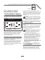
Testing the GFCI
Test your GFCI outlet every month, as follows:
Push the black Test button. The red Reset button
should pop out, which should allow no power to
reach the outlet. Use a test lamp in each outlet to
test this.
DANGER: If the Reset button does not pop
out or the test lamp remains lit when the
Reset button is popped out, do not use any
outlets on the circuit. Call a qualified electrician.
If the GFCI tests good, restore power by pressing
the Reset button firmly until it is fully in place and
locks in that position. If the GFCI outlet does not
reset properly, do not use the outlet call a
qualified electrician.
If the GFCI trips by itself at any time, reset and test
the outlet. If the reset button does pop out when
the test button is pressed, do not use the outlet.
Call a qualified electrician.
120/240 Volt AC, 30 Amp, Locking
Receptacle
Use a NEMA L1430 plug with this receptacle.
Connect a 4wire cord set rated for 250 Volt AC loads
at 30 Amps (or greater) (Figure 11). You can use the
same 4wire cord if you plan to run a 120 Volt load.
MEGAFORCE 6500 Extended Life Generator
10
Figure 10 120 Volt AC, 15 Amp GFCI Receptacle

MEGAFORCE 6500 Extended Life Generator
11
This receptacle powers 120/240 Volt AC, 60 Hz, single
phase loads requiring up to 3,600 watts of power at
30 Amps for 120 Volts; 6,500 watts of power (6.5 kW)
at 30 Amps for 240 Volts. The outlet is protected by a
30 Amp pushtoreset circuit breaker.
CAUTION: Although this outlet is rated for
30 Amps (up to 7,200 watts), the generator is
only rated for 6,500 watts. Powering loads that
exceed the wattage/amperage capacity of the
unit can damage it or cause serious injuries.
Loads of 240 Volts powered through this outlet
should not exceed 27 Amps current draw;
120 Volt loads should not exceed 30 Amps.
120 Volt AC, 30 Amp Locking
Receptacle
Use a NEMA L530 plug with this receptacle. Connect
a 3wire cord set rated for 125 Volt AC loads at
30 Amps to the plug (Figure 12).
Use this receptacle to operate 120 Volt AC, 60 Hz,
single phase loads requiring up to 3,600 watts
(3.6 kW) of power at 30 Amps. The outlet is protected
by a 30 Amp pushtoreset circuit breaker.
12 Volt DC, 10 Amp Receptacle
This receptacle (Figure 13) allows you to recharge a
12 Volt automotive or utility style storage battery with
the battery charge cables provided.
This receptacle can not recharge 6 Volt batteries and
can not be used to crank an engine having a
discharged battery. See Charging a Battery on
page 8 before attempting to recharge a battery. This
outlet is protected by a 10 Amp self resetting circuit
breaker.
Figure 12 120 Volt AC, 30 Amp, Locking Receptacle
Figure 13 12 Volt DC, 10 Amp Receptacle
Figure 11 120/240 Volt AC, 30 Amp, Locking
Receptacle

MEGAFORCE 6500 Extended Life Generator
12
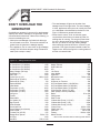
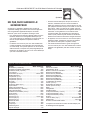
DONT OVERLOAD THE
GENERATOR
Overloading a generator in excess of its rated wattage
capacity can result in damage to the generator and/or
connected electrical devices. Observe the following, to
prevent overloading the unit:
Add up the total wattage of all electrical devices to
be connected at one time. This total should NOT be
greater than the generators wattage capacity.
If the appliance, tool or motor does not give wattage,
multiply 120 Volts times ampere rating to determine
watts (volts x amps = watts).
The rated wattage of lights can be taken from
wattage listed on the light bulbs. The rated wattage
of tools, appliances and motors can usually be found
on a data plate or decal affixed to the device. Use
Figure 14 below as a general reference.
Some electric motors, such as induction types,
require about three times more watts of power for
starting than for running. This surge of power lasts
for only a few seconds when starting such motors.
Be sure you allow for this high starting wattage
when selecting electrical devices to connect to your
generator. First figure the watts needed to start the
largest motor. Add to that figure the running watts of
all other connected loads.
Device . . . . . . . . . . . . . . . . . . . . . . . . . Load (watts)
*Air Conditioner (12,000 Btu). . . . . . . . . . . . . . . 1700
*Air Conditioner (24,000 Btu). . . . . . . . . . . . . . . 3800
*Air Conditioner (40,000 Btu). . . . . . . . . . . . . . . 6000
Battery Charger (20 Amp) . . . . . . . . . . . . . . . . . . 500
Belt Sander (3") . . . . . . . . . . . . . . . . . . . . . . . . 1000
Chain Saw . . . . . . . . . . . . . . . . . . . . . . . . . . . . 1200
Circular Saw (6-1/2") . . . . . . . . . . . . . . . 800 to 1000
*Clothes Dryer (Electric) . . . . . . . . . . . . . . . . . . 5750
*Clothes Dryer (Gas). . . . . . . . . . . . . . . . . . . . . . 700
*Clothes Washer . . . . . . . . . . . . . . . . . . . . . . . . 1150
Coffee Maker . . . . . . . . . . . . . . . . . . . . . . . . . . 1750
*Compressor (1 HP) . . . . . . . . . . . . . . . . . . . . . 2000
*Compressor (3/4 HP) . . . . . . . . . . . . . . . . . . . . 1800
*Compressor (1/2 HP) . . . . . . . . . . . . . . . . . . . . 1400
Curling Iron . . . . . . . . . . . . . . . . . . . . . . . . . . . . . 700
*Freezer . . . . . . . . . . . . . . . . . . . . . . . . . . . . . . . 700
*Dehumidifier . . . . . . . . . . . . . . . . . . . . . . . . . . . 650
Disc Sander (9") . . . . . . . . . . . . . . . . . . . . . . . . 1200
Edge Trimmer . . . . . . . . . . . . . . . . . . . . . . . . . . . 500
Electric Blanket . . . . . . . . . . . . . . . . . . . . . . . . . . 400
Electric Nail Gun . . . . . . . . . . . . . . . . . . . . . . . . 1200
Electric Range (per element). . . . . . . . . . . . . . . 1500
Electric Skillet . . . . . . . . . . . . . . . . . . . . . . . . . . 1250
*Furnace Fan (3/5 HP) . . . . . . . . . . . . . . . . . . . . 875
*Garage Door Opener . . . . . . . . . . . . . . . 500 to 750
Hair Dryer . . . . . . . . . . . . . . . . . . . . . . . . . . . . . 1200
Hand Drill . . . . . . . . . . . . . . . . . . . . . . . . 250 to 1100
Device . . . . . . . . . . . . . . . . . . . . . . . . . Load (watts)
Hedge Trimmer . . . . . . . . . . . . . . . . . . . . . . . . . . 450
Impact Wrench . . . . . . . . . . . . . . . . . . . . . . . . . . 500
Iron . . . . . . . . . . . . . . . . . . . . . . . . . . . . . . . . . . 1200
*Jet Pump. . . . . . . . . . . . . . . . . . . . . . . . . . . . . . 800
Lawn Mower . . . . . . . . . . . . . . . . . . . . . . . . . . . 1200
Light Bulb . . . . . . . . . . . . . . . . . . . . . . . . . . . . . . 100
Microwave Oven. . . . . . . . . . . . . . . . . . . 700 to 1000
*Milk Cooler. . . . . . . . . . . . . . . . . . . . . . . . . . . . 1100
Oil Burner on Furnace. . . . . . . . . . . . . . . . . . . . . 300
Oil Fired Space Heater (140,000 Btu) . . . . . . . . . 400
Oil Fired Space Heater (85,000 Btu) . . . . . . . . . . 225
Oil Fired Space Heater (30,000 Btu) . . . . . . . . . . 150
*Paint Sprayer, Airless (1/3 HP) . . . . . . . . . . . . . . 600
Paint Sprayer, Airless (handheld). . . . . . . . . . . . . 150
Radio . . . . . . . . . . . . . . . . . . . . . . . . . . . . . 50 to 200
*Refrigerator . . . . . . . . . . . . . . . . . . . . . . . . . . . . 700
Slow Cooker . . . . . . . . . . . . . . . . . . . . . . . . . . . . 200
*Submersible Pump (1-1/2 HP) . . . . . . . . . . . . . 2800
*Submersible Pump (1 HP) . . . . . . . . . . . . . . . . 2000
*Submersible Pump (1/2 HP). . . . . . . . . . . . . . . 1500
*Sump Pump . . . . . . . . . . . . . . . . . . . . . 800 to 1050
*Table Saw (10"). . . . . . . . . . . . . . . . . . 1750 to 2000
Television . . . . . . . . . . . . . . . . . . . . . . . . . 200 to 500
Toaster . . . . . . . . . . . . . . . . . . . . . . . . . 1000 to 1650
Weed Trimmer . . . . . . . . . . . . . . . . . . . . . . . . . . 500
* Allow 3 times the listed watts for starting these devices.
Figure 14 Wattage Reference Guide

MEGAFORCE 6500 Extended Life Generator
13
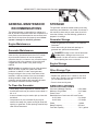
GENERAL MAINTENANCE
RECOMMENDATIONS
The Owner/Operator is responsible for making sure
that all periodic maintenance tasks are completed on a
timely basis; that all discrepancies are corrected; and
that the unit is kept clean and properly stored. Never
operate a damaged or defective generator.
Engine Maintenance
See engine owners manual for instructions.
Generator Maintenance
Generator maintenance consists of keeping the unit
clean and dry. Operate and store the unit in a clean
dry environment where it will not be exposed to
excessive dust, dirt, moisture or any corrosive vapors.
Cooling air slots in the generator must not become
clogged with snow, leaves or any other foreign
material.
NOTE: Do Not use a garden hose to clean generator.
Water can enter engine fuel system and cause
problems. In addition, if water enters generator
through cooling air slots, some of the water will be
retained in voids and cracks of the rotor and stator
winding insulation. Water and dirt buildup on the
generator internal windings will eventually decrease
the insulation resistance of these windings.
To Clean the Generator
Use a damp cloth to wipe exterior surfaces clean.
A soft bristle brush may be used to loosen caked on
dirt or oil.
A vacuum cleaner may be used to pick up loose dirt
and debris.
Low pressure air (not to exceed 25 psi) may be
used to blow away dirt. Inspect cooling air slots and
opening on generator. These openings must be kept
clean and unobstructed.
STORAGE
The generator should be started at least once every
seven days and allowed to run at least 30 minutes. If
this cannot be done and you must store the unit for
more than 30 days, use the following guidelines to
prepare it for storage.
Generator Storage
Clean the generator as outlined in To Clean the
Generator.
Check that cooling air slots and openings on
generator are open and unobstructed.
DANGER! Storage covers can be flammable.
Do Not place a storage cover over a hot
generator. Let the unit cool for a sufficient time
before placing the cover on the unit.
Engine Storage
See engine owners manual for instructions.
Other Storage Tips
Do Not store gasoline from one season to another.
Replace the gasoline can if it starts to rust. Rust
and/or dirt in gasoline can cause problems when
you use that fuel with this unit.
Store in clean and dry area.
SPECIFICATIONS
Continuous Wattage Capacity . . . . . . . 6,500 watts
Maximum Surge Watts . . . . . . . . . . . . 8,125 watts
Power Factor . . . . . . . . . . . . . . . . . . . 1.0
Rated Maximum Continuous AC Load Current:
At 120 Volts . . . . . . . . . . . . . . . . . . 54.1 Amps
At 240 Volts . . . . . . . . . . . . . . . . . . 27.0 Amps
Phase. . . . . . . . . . . . . . . . . . . . . . . . . 1 phase
Rated Frequency . . . . . . . . . . . . . . . . 60 Hertz
Fuel Tank Capacity . . . . . . . . . . . . . . . 7 U.S. gallons

MEGAFORCE 6500 Extended Life Generator
14
NOTES

MEGAFORCE 6500 Extended Life Generator
15
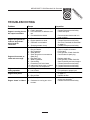
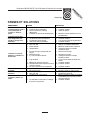
TROUBLESHOOTING
Problem Cause Correction
Engine is running, but no
AC output is available.
1. One of the circuit breakers is open.
2. Fault in generator.
3. Poor connection or defective cord
set.
4. Connected device is bad.
1. Reset circuit breaker.
2. Contact Generac service facility.
3. Check and repair.
4. Connect another device that is in
good condition.
Engine runs good at no-
load but bogs down
when loads are
connected.
1. Short circuit in a connected load.
2. Engine speed is too slow.
3. Generator is overloaded.
4. Shorted generator circuit.
1. Disconnect shorted electrical load.
2. Contact Generac service facility.
3. See Dont Overload the Generator
on page 12.
4. Contact Generac service facility.
Engine will not start; or
starts and runs rough.
1. Run/Stop switch set to Stop.
2. Dirty air cleaner.
3. Out of gasoline.
4. Stale gasoline.
5. Spark plug wire not connected to
spark plug.
6. Bad spark plug.
7. Water in gasoline.
8. Overchoking.
9. Excessively rich fuel mixture.
10. Intake valve stuck open or closed.
11. Engine has lost compression.
1. Set switch to Run.
2. Clean or replace air cleaner.
3. Fill fuel tank.
4. Drain gas tank; fill with fresh fuel.
5. Connect wire to spark plug.
6. Replace spark plug.
7. Drain gas tank; fill with fresh fuel.
8. Open choke fully and crank engine.
9. Contact Generac service facility.
10. Contact Generac service facility.
11. Contact Generac service facility.
Engine shuts down
during operation.
1. Out of gasoline.
2. Low oil level.
1. Fill fuel tank.
2. Fill crankcase to proper level.
Engine lacks power.
1. Load is too high.
2. Dirty air filter.
1. See Dont Overload the Generator
on page 12.
2. Replace air filter.
Engine hunts or falters.
1. Choke is opened too soon.
2. Carburetor is running too rich or
too lean.
1. Move choke to halfway position until
engine runs smoothly.
2. Contact Generac service facility.

MEGAFORCE 6500 Extended Life Generator
16
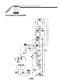
SCHEMATIC DIAGRAM

MEGAFORCE 6500 Extended Life Generator
17
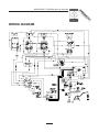
WIRING DIAGRAM

MEGAFORCE 6500 Extended Life Generator
18
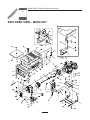
EXPLODED VIEW MAIN UNIT

MEGAFORCE 6500 Extended Life Generator
19
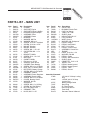
Item Part # Qty Description
1 B92432 1 CRADLE
2 B92531 1 SUPPORT, Engine
3 B92731 1 SUPPORT, Engine & Muffler
4 92247 1 HOUSING, Engine Adapter
5 92679G 1 ASSEMBLY, Rotor
6 92681G 1 ASSEMBLY, Stator
7 65791 1 BEARING
8 67451 1 WASHER, M8 Flat
9 22129 14 WASHER, M8 Lock
10 86307 4 SCREW, 5/16-24 x 3/4 Mach.
11 25254 1 SCREW, 5/16-24 x 9-7/8"
12 92609 2 MOUNT, Vibration
13 82857 4 MOUNT, Vibration
14 40976 2 SCREW, M8 - 1.25 x 20
15 66476 2 CAPSCREW, M6 - 1.0 x
12mm
16 92532 1 BRACKET, Muffler
17 22142 2 SCREW, 5/16 - 18 x 3/4"
18 91153 1 MUFFLER
19 90239 1 GASKET, Muffler
20 81917 1 PIN, 4 mm x 10 Roll
24 83083 1 SCREEN, Spark Arrest
25 66825C 1 CARRIER, Rear Bearing
26 74908 4 SCREW, M5-0.8 x 10 Taptite
27 86308B 4 BOLT, M6-1 x 165mm Stator
28 65795 1 RECTIFIER, Battery Charge
29 66849A 1 SCREW, M5-0.8 x 20 Taptite
30 67022 1 GROMMET, Rubber
31 84132 1 ASSEMBLY, Power Regulator
32 66386 1 ASSEMBLY, Brush Holder
33 66849 2 SCREW, M5-0.8 x 16 Taptite
34 B67025 1 COVER, Bearing Carrier
35 22769 1 WASHER, #10 Int.
Shakeproof
36 86494 1 SCREW, M6-1.0 x 16 Wing
37 86292 7 SCREW, #10 Self Drilling
38 77395 4 NUT, M6 Flange Lock
39 83465 4 GROMMET, Tank
40 57058 4 HHCS, M6-1.0 x 55
Item Part # Qty Description
41 80270 1 VALVE, Tank
42 78299 1 BUSHING, Plastic Tank
43 B4363 1 CAP, Fuel Gauge
44 B1695 1 TANK, Fuel 7-Gal
45 B92039 1 SHIELD, Heat
46 92665 1 INSULATION, #2-1/4"
47 85000 1 CLIP, Insulation
48 14353621 1 WIRE, Ground
49 26850 2 WASHER, M6 Shakeproof
51 94479 1 DECAL, Danger
52 B1223 2 DECAL, Heat Shield
55 25244 12 NUT, 5/16-18 Hex
57 B1224 1 DECAL, Control Panel
58 B1473 1 ASSEMBLY, Control Box
59 NSP 1 ENGINE
60 22531 2 HHCS, 5/16-18 x 1-3/4
61 22473 4 WASHER, Flat M6
62 93221 2 DECAL, Cradle
63 94480 1 DECAL, Start Instructions
64 B96068 1 SHIELD, Heat
65 56893 5 CRIMPTITE, 10-24 x 1/2
66 NSP 1 DECAL, CSA
67 74728 1 DECAL, Neutral ground
68 76247 1 DECAL, Neutral ground
69 20566 1 DECAL, 1-800
70 B4986 1 DECAL, Ground
Items Not Illustrated:
37806 120 Volt AC 30 Amp Locking
Plug
43438 120/240 Volt AC 30 Amp
Locking Plug
65787 Battery Charge Cable
72347 Spark Plug
73111 Air Filter Element
84882 Spark Plug Wrench
84883 Cord Wrap
B1479 Generator Owners Manual
PARTS LIST MAIN UNIT

MEGAFORCE 6500 Extended Life Generator
20
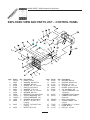
Item Part # Qty. Description
1 F92570 1 PANEL, Control
2 23897 4 WASHER, #10 M5 Flat
3 49226 4 WASHER, M5 Lock
4 91526 4 SCREW, M5 - 0.8 x 12mm
5 87968 1 SWITCH, Idle Control
6 82881 4 WASHER, 7/16" Lock
7 43181 8 SCREW, M3 - 0.5 x 10mm
8 43182 8 WASHER, M3 Lock
9 66822 1 BRACKET, 12V Outlet & Ret.
10 75207A 2 CIRCUIT BREAKER, 30A
11 75207D 1 CIRCUIT BREAKER, 15A
12 23365 6 WASHER, #8 Shakeproof
13 68868 1 OUTLET, 120 Volt, 30 A
Locking
14 43437 1 OUTLET, 120V/240V, 30A
Locking
15 94373 1 RECEP, GFCI 15A
Item Part # Qty. Description
16 43108 6 WASHER, M4 Flat
17 22264 6 WASHER, #8 M4 Lock
18 51715 6 NUT, M4 - 0.7 Hex
19 64526 8 SCREW, #6 - 32 x 3/8"
20 83907 1 BOARD, System Control
21 64525 4 3/4" Hex Stand - Off
22 87692 1 CIRCUIT BREAKER, 12V,
10A (auto)
23 84335 1 ASSEMBLY, Wire Harness
24 84134 1 CONNECTION, Rubber
Grommet
25 B92069 1 BOX, Control Panel
26 84028 1 TRANSFORMER , Idle
Control
27 75475 6 SCREW, M4 - 0.7 x 10mm
28 77604 1 HOUR METER
29 51714 2 NUT, M3 - 0.5 Hex
EXPLODED VIEW AND PARTS LIST CONTROL PANEL
La page charge ...
La page charge ...
La page charge ...
La page charge ...
La page charge ...
La page charge ...
La page charge ...
La page charge ...
La page charge ...
La page charge ...
La page charge ...
La page charge ...
La page charge ...
La page charge ...
La page charge ...
La page charge ...
-
 1
1
-
 2
2
-
 3
3
-
 4
4
-
 5
5
-
 6
6
-
 7
7
-
 8
8
-
 9
9
-
 10
10
-
 11
11
-
 12
12
-
 13
13
-
 14
14
-
 15
15
-
 16
16
-
 17
17
-
 18
18
-
 19
19
-
 20
20
-
 21
21
-
 22
22
-
 23
23
-
 24
24
-
 25
25
-
 26
26
-
 27
27
-
 28
28
-
 29
29
-
 30
30
-
 31
31
-
 32
32
-
 33
33
-
 34
34
-
 35
35
-
 36
36


Simplicity 01021-0 Le manuel du propriétaire
- Catégorie
- Groupes électrogènes
- Taper
- Le manuel du propriétaire
- Ce manuel convient également à
dans d''autres langues
- English: Simplicity 01021-0 Owner's manual