Webasto Wiring Guide d'installation
- Catégorie
- Thermostats
- Taper
- Guide d'installation

Webasto Heating and Cooling
Installation Guide for Kit Numbers:
• 5014030A – Moscow Harness Kit – NEO 1
• 5014028A – Kiev Harness Kit – NEO 2
• 5014029A – Moscow Harness Kit – NEO 1
• 5014027A – Kiev Harness Kit – NEO 2 (extended harness)
• 5014037A – Kiev Harness Kit – NEO 2+
Contents
General Service and Safety Precautions ................................................................................................................ 2
Installation General References ............................................................................................................................ 2
SPECIAL NOTES ....................................................................................................................................................... 2
VAC Wiring Diagram – NEO 1 ................................................................................................................................. 5
HVAC Wiring Connections – NEO 2 ........................................................................................................................ 6
HVAC Wiring Diagram – NEO 2+ ............................................................................................................................ 7
Relay Board ............................................................................................................................................................. 8
Condenser Information – Fuse Usage ................................................................................................................... 8
System Diagram HVAC Board Extreme .................................................................................................................... 9
NEO 1 A/C Details ................................................................................................................................................. 10
NEO 2 HVAC Independent Details ......................................................................................................................... 10
NEO 2+ HVAC Details ........................................................................................................................................... 11
Warning: Cancer and Reproductive Harm. www.P65Warnings.ca.gov
– Installation and repair of Webasto heating and cooling systems requires special Webasto
training, technical information, special tools and special equipment.
– NEVER attempt to install or repair Webasto heating or cooling system unless you have
the proper certifications, technical skills, tools, and equipment required to properly
complete the necessary procedures.
– ALWAYS carefully follow Webasto installation and repair instructions and heed all
WARNINGS.
– Webasto rejects any liability for problems and damage caused by the system being
installed by untrained personnel.

2
INTRODUCTION
General Service and Safety Precautions
WARNING
Never service, repair, or troubleshoot this system unless you are a professional air
conditioning/refrigeration service person. Improper servicing can lead to serious injury or death from fire,
electric shock, or explosion.
Refrigeration and air conditioning devices are extremely complicated by nature. Servicing, repairing, and
Trouble-shooting these products should be done only by those with the necessary knowledge, training,
and equipment.
Installation General References
• Disconnect the negative battery cable before performing any work on the vehicle’s electrical
system.
• Bare sheet metal, for example around drilled holes, must be treated with anti-corrosive coating.
• Secure hoses, cables and wiring harnesses with cable ties and fit protective hoses around them at
chafing points.
• Fit edge protectors (split fuel hose, grommet, split-loom, etc.) to sharp edges.
• Replace hose clamps as necessary. Hose clamps should be inspected before re-use. Look for
damage to the screw and to the band due to fatigue, corrosion, or improper installation.
SPECIAL NOTES
Warning: All power connections are to be made at the battery.
Caution: Remove the three 15A fuses from the relay board and replace them with 20A fuses when an
underbody-mounted, or Valencia rooftop-mounted condenser is being used. Refer to page 8 for more info.
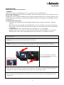
Be sure the thermostat connectors
are connected to the brass terminals,
not the silver terminals.
When making power connections, the battery connections must be made last. Failure to follow this direction
could result in a short circuit and damage to the vehicle or the system being installed.
Before cutting the mounting hole for the controller, be sure there is no structure or wiring behind it that can
be damaged.

3
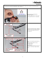
In some cases, not all wiring connectors / wires will be used. In these cases, secure the unused connectors /
wires to the wiring harness and protect against damage.
Insert the blue wire labeled AC
BLOWER ON from
the NEO adapter harness into cavity C
of the blower harness X1 connector.
Connect the blower harness and NEO
adapter harness to the NEO controller.
Install the dome light bezel on the
package tray.
Connect the following connectors to
the
NEO controller adapter harness:
o coolant pump
o coolant valve
o compressor
Secure unused connectors to the wire
harness as necessary using electrical
tape.

4
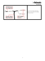
Connect the extreme relay board
harness to the thermostat and NEO
adapter harnesses.

5
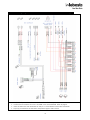
VAC Wiring Diagram – NEO 1
Fig. 1
• Caution: All power connections are to be made at the battery.
• Confirm that the correct fuse size is installed in the extreme board. Refer to page 8.
• Insert the blue wire from connector J2 into pin C of the blower harness NEO connector
•
Tape any unused wires or connectors and protect against short-circuits

6
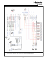
HVAC Wiring Connections – NEO 2
Fig. 2
Caution: All power connections are to be made at the battery.
Confirm that the correct fuse size is installed in the extreme board. Refer to page 8.

7
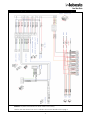
HVAC Wiring Diagram – NEO 2+
Fig. 3
Caution: All power connections are to be made at the battery.
Confirm that the correct fuse size is installed in the extreme board. Refer to page 8.

8
Condenser Information – Fuse Usage
Condenser Name Dimensions
L x W x H – in (mm)
Fuse size installed in
extreme board
Capri (rooftop) 32 X 23.6 X 5.9
(815 X 600 X 150) 15 amp
Valencia (rooftop) 37.5 X 23.6 X 5.9
(955 X 600 X 150) 20 amp
Underbody 28.5 X 17.7 X 4.1
(725 X 450 X 105) 20 amp
Relay Board
Fig. 4
Caution: Remove the three 15A fuses from the relay board and replace them with 20A fuses.
Caution: All power connections are to be made at the battery. Failure to follow this instruction will
cause damage to kit components.

9
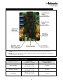
Caution: All power connections are to be made at the battery. Failure to follow this instruction will cause
damage to kit components.
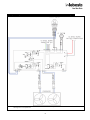
System Diagram HVAC Board Extreme
Fig. 5

10
X
X
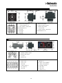
NEO 1 A/C Details
Fig. 6
J1 – Output for compressor
clutch/condenser fan
J2 – Input enable - compressor
clutch/condenser fan
J3 – Ground
J4 – Backlight
J5 – Ground
J6 - +12V DC
L – Blower low speed
M – Blower medium speed
H – Blower high speed
B - +12V DC (B+)
C – Output enable - compressor
clutch/condenser fan
NEO 2 HVAC Independent Details
Fig. 7
L – Blower low speed
M – Blower medium speed
H – Blower high speed
B - +12V DC
C – Blower ON
1 - +12V DC
2 – Water valve
3 – water valve
4 – Not used
5 – Coolant pump (+)
6 – A/C clutch (+)
7 – Not used
8 – Ground
9 – Ignition (+)
10 – Water valve feedback
11 – Water valve ground
12 – Backlight control
13 – Not used
14 – Not used
15 – Blower ON (+)

11
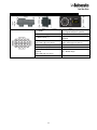
NEO 2+ HVAC Details
Fig. 8
1 - +12VDC
9 – Ignition (+) (independent)
Engine ON (tie-in systems)
2 – Water Valve (-)
10 – Water Valve Reference
3 – Water Valve (+)
11 – Output Sensor / Water Valve
Ground
4 – Input Temperature Sensor
(NTC 10K Ω @ 77°F (25°C)
12 – Output Sensor
(NTC 10K Ω @ 77°F (25°C)
5 – Coolant Pump (+)
13 – Blower Low
6 – Compressor (+)
14 – Blower Medium
7 – Internal Temperature Sensor
(ground)
(NTC 10K Ω @ 77°F (25°C)
15 – Blower High
8 – GND

If you have any questions, contact our technical support team at (800) 860-7866 or via email at technical@webasto.com.
In multilingual versions the English language is binding. The telephone number of the respective country is shown on the
Webasto service center leaflet or can be found on the website of your Webasto subsidiary.
Dans le cas d’une version rédigée en plusieurs langues, l’anglais est alors la langue qui fait foi. Pour trouver le numéro de
téléphone du pays concerné, veuillez consulter le dépliant des points-service Webasto ou la page web de la représentation
Webasto de votre pays.
Webasto Thermo & Comfort N.A., Inc.
15083 North Road
Fenton, MI 48430
Technical Assistance Hotline
USA: (800) 860-7866
Canada: (800) 667-8900
www.webasto.us
www.techwebasto.com
Org. 03/2022 Rev. 9/2022 im_5014026a_wiring
-
 1
1
-
 2
2
-
 3
3
-
 4
4
-
 5
5
-
 6
6
-
 7
7
-
 8
8
-
 9
9
-
 10
10
-
 11
11
-
 12
12


Webasto Wiring Guide d'installation
- Catégorie
- Thermostats
- Taper
- Guide d'installation
Documents connexes
-
Webasto Ram ProMaster London/Vancouver/Sedona - Front Mounting Kit - Guide d'installation
-
-
-
-
-
-
-
-
-
Webasto SmarTemp Control fx 2.0 Installation / Mode d'emploi