
EN
DE
FR
ES
Operating instructions
Betriebsanleitung
Mode d'emploi
Manual de instrucciones
Temperaturschalter Typ TSD-30
Temperature switch model TSD-30
Temperature switch model TSD-30
Thermostat type TSD-30
Termóstato modelo TSD-30

2 WIKA operating instructions temperature switch model TSD-30
EN
DE
FR
ES
© 2011 WIKA Alexander Wiegand SE & Co. KG
All rights reserved. / Alle Rechte vorbehalten.
WIKA
®
is a registered trademark in various countries.
WIKA
®
ist eine geschützte Marke in verschiedenen Ländern.
Prior to starting any work, read the operating instructions!
Keep for later use!
Vor Beginn aller Arbeiten Betriebsanleitung lesen!
Zum späteren Gebrauch aufbewahren!
Lire le mode d‘emploi avant de commencer toute opération !
A conserver pour une utilisation ultérieure !
¡Leer el manual de instrucciones antes de comenzar cualquier trabajo!
¡Guardar el manual para una eventual consulta posterior!
Operating instructions model TSD-30 Page 3 - 30
Betriebsanleitung Typ TSD-30 Seite 31 - 58
Mode d‘emploi type TSD-30 Page 59 - 86
Manual de instrucciones modelo TSD-30 Página 87 - 115
11613025.04 05/2018 EN/DE/FR/ES

3WIKA operating instructions temperature switch, model TSD-30
EN
11613025.04 05/2018 EN/DE/FR/ES
Declarations of conformity can be found online at www.wika.com.
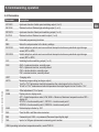
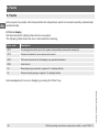
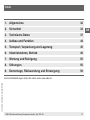
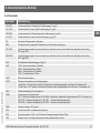
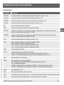
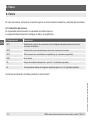
1. General information 4
2. Safety 6
3. Specications 9
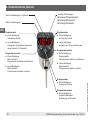
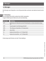
4. Design and function 16
5. Transport, packaging and storage 17
6. Commissioning, operation 18
7. Maintenance and cleaning 27
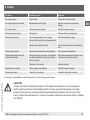
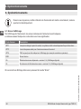
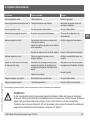
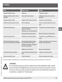
8. Faults 28
9. Dismounting, return and disposal 30
Contents

4 WIKA operating instructions temperature switch, model TSD-30
EN
11613025.04 05/2018 EN/DE/FR/ES
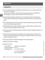
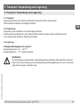
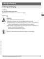
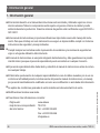
1. General information
■
The temperature switch described in the operating instructions has been designed and manufactured
using state-of-the-art technology. All components are subject to stringent quality and environ
mental
criteria during production. Our management systems are certied to ISO 9001 and ISO 14001.
■
These operating instructions contain important information on handling the instrument. Working safely
requires that all safety instructions and work instructions are observed.
■
Observe the relevant local accident prevention regulations and general safety regulations for the
instrument's range of use.
■
The operating instructions are part of the product and must be kept in the immediate vicinity of the
instrument and readily accessible to skilled personnel at any time.
■
Skilled personnel must have carefully read and understood the operating instructions prior to begin-
ning any work.
■
The manufacturer's liability is void in the case of any damage caused by using the product contrary to
its intended use, non-compliance with these operating instructions, assignment of insuciently quali-
ed skilled personnel or unauthorised modications to the instrument.
■
The general terms and conditions contained in the sales documentation shall apply.
■
Subject to technical modications.
■
Further information:
- Internet address: www.wika.de / www.wika.com
- Relevant data sheet: TE 67.03
- Application consultant:
Tel.: +49 9372 132-8976
Fax: +49 9372 132-8008976
1. General information

5WIKA operating instructions temperature switch, model TSD-30
EN
11613025.04 05/2018 EN/DE/FR/ES
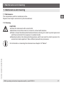
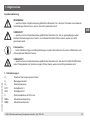
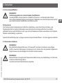
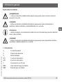
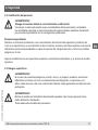
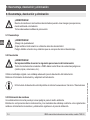
Explanation of symbols
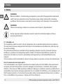
WARNING!
... indicates a potentially dangerous situation that can result in serious injury or death, if not
avoided.
CAUTION!
... indicates a potentially dangerous situation that can result in light injuries or damage to
equipment or the environment, if not avoided.
Information
… points out useful tips, recommendations and information for ecient and trouble-free
operation.
CAUTION!
... indicates a potentially dangerous situation that can result in burns, caused by hot
surfaces or liquids, if not avoided.
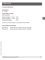
Abbreviations
U
+
Positive power terminal
U
-
Reference potential
S
+
Analogue output
SP1 1 switch point
SP2 2 switch point
C Communication with IO-Link
MBA Start of measuring range
MBE End of measuring range
1. General information

6 WIKA operating instructions temperature switch, model TSD-30
EN
11613025.04 05/2018 EN/DE/FR/ES
2. Safety
WARNING!
Before installation, commissioning and operation, ensure that the appropriate temperature
switch has been selected in terms of measuring range, design and specic measuring
conditions.
Non-observance can result in serious injury and/or damage to the equipment.
WARNING!
Observe the working conditions in accordance with chapter 3 „Specications”.
Further important safety instructions can be found in the individual chapters of these
operating instructions.
2.1 Intended use
The temperature switch is used to convert temperature into an electrical signal indoors and outdoors.
The instrument has been designed and built solely for the intended use described here, and may only
be used accordingly.
The technical specications contained in these operating instructions must be observed. Improper
handling or operation of the temperature switch outside of its technical specications requires the
instrument to be taken out of service immediately and inspected by an authorised WIKA service
engineer.
The manufacturer shall not be liable for claims of any type based on operation contrary to the intended use.
Use of accessories and spare parts
It is recommended to use original accessories and original spare parts from WIKA. Using accessories
and spare parts from third parties can lead to damage to the instrument or accidents, due to quality
defects or other reasons. WIKA assumes no liability for damage or accidents caused by a malfunction or
unsuitability of accessories and spare parts which do not originate from WIKA (e.g. non-compliance with
the IP ingress protection of connectors). No warranty claims can be made which arise due to a malfunc-
tion or unsuitability of any accessory or spare part from a third party.
2. Safety

7WIKA operating instructions temperature switch, model TSD-30
EN
11613025.04 05/2018 EN/DE/FR/ES
2.2 Personnelqualication
WARNING!
Riskofinjuryshouldqualicationbeinsucient!
Improper handling can result in considerable injury and damage to equipment.
The activities described in these operating instructions may only be carried out by skilled
personnel who have the qualications described below.
Skilled personnel
Skilled personnel are understood to be personnel who, based on their technical training, knowledge
of measurement and control technology and on their experience and knowledge of country-specic
regulations, current standards and directives, are capable of carrying out the work described and
independently recognising potential hazards.
Special operating conditions require further appropriate knowledge, e.g. of aggressive media.
2.3 Special hazards
WARNING!
For hazardous media such as oxygen, acetylene, ammable or toxic gases or liquids,
and refrigeration plants, compressors, etc., in addition to all standard regulations, the
appropriate existing codes or regulations must also be followed.
WARNING!
Residual media in the dismounted temperature switch can result in a risk to persons, the
environment and equipment.
Take sucient precautionary measures.
2. Safety

8 WIKA operating instructions temperature switch, model TSD-30
EN
11613025.04 05/2018 EN/DE/FR/ES
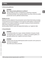
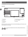
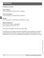
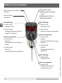
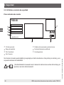
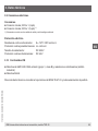
2.4 Labelling, safety marks
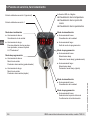
Product label
2. Safety
IO-Link (option)
Pin assignment and specications
Measuring range
Coded date of production
P# Product No.
Approvals
S# Serial No.
If the serial number becomes illegible (e.g. due to mechanical damage or overpainting), traceability will
no longer be possible.
Before mounting and commissioning the instrument, ensure you read the operating
instructions!
TSD-30
-20 ... +120 °C
P# 14266568
S# 110AKMAR
www.wika.com
8A
connection diagramm

9WIKA operating instructions temperature switch, model TSD-30
EN
11613025.04 05/2018 EN/DE/FR/ES
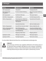
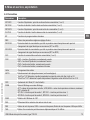
3.Specications
3. Specications
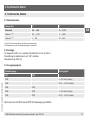
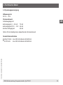
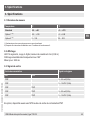
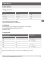
3.1 Measuring ranges
Temperature °C °F
Standard -20 ... +80 -4 ... +176
Option 1
1) 2)
-20 ... +120 -4 ... +248
Option 2
1) 2)
0 ... 150 32 ... 302
1) Only for process connections with compression tting.
2) Installation instructions under “Operating conditions” must be observed.
3.2 Display
14-segment LED, red, 4-digit, 9 mm (0.35 in) character size
Display can be turned electronically through 180°
Update: 200 ms
3.3 Output signal
Switching output Analogue signal
SP1 SP2
PNP - 4 ... 20 mA (3-wire)
PNP - DC 0 ... 10 V (3-wire)
PNP PNP -
PNP PNP 4 ... 20 mA (3-wire)
PNP PNP DC 0 ... 10 V (3-wire)
Optionally also available with an NPN instead of a PNP switching output.

10 WIKA operating instructions temperature switch, model TSD-30
EN
11613025.04 05/2018 EN/DE/FR/ES
3.Specications
IO-Link, revision 1.1 (option)
IO-Link is optionally available for all output signals.
With the IO-Link option, switching output SP1 is always PNP
Switching thresholds
Switch point 1 and switch point 2 are individually adjustable
Switching functions
Normally open, normally closed, window, hysteresis freely adjustable
Switching voltage:
Power supply
- 1 V
Switching current
■
without IO-Link: max. 250 mA
■
with IO-Link: SP1 max. 100 mA, SP2 max. 250 mA
Adjustment accuracy
≤ 0.5 % of span
Temperatureosetadjustment
±3 % of span
Scaling
Zero point: 0 ... 25 % of span
Full scale: 75 ... 100 % of span
Load
Analogue signal 4 ... 20 mA: ≤ 0.5 kΩ
Analogue signal DC 0 ... 10 V: > 10 kΩ
Service life
100 million switching cycles

11WIKA operating instructions temperature switch, model TSD-30
EN
11613025.04 05/2018 EN/DE/FR/ES
3.Specications
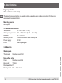
3.4 Voltage supply
Power supply U
+
DC 15 ... 35 V
Current consumption
Switching outputs with
■
Analogue signal 4 ... 20 mA: 70 mA
■
Analogue signal DC 0 ... 10 V: 45 mA
■
without analogue signal: 45 mA
IO-Link option causes a deviating current consumption
Total current consumption
■
without IO-Link: max. 600 mA including switching current
■
with IO-Link: max. 450 mA including switching current

12 WIKA operating instructions temperature switch, model TSD-30
EN
11613025.04 05/2018 EN/DE/FR/ES
3.Specications
3.5 Accuracy data
Analogue signal
≤ ±0.5 % of span + temperature sensor error
Switching output
≤ ±0.8 % of span + temperature sensor error
Display
≤ ±(0.8 % of span + temperature sensor error) ±1 digit
Temperature sensor
For °C: ±(0.15 K + 0.002 | t |) per EN 60751
For °F: ±[1.8*(0.15 + 0.002 (t - 32) / 1.8)]
|T| is the value of the temperature without consideration of the sign.
The actually achievable accuracy is signicantly determined by the mounting situation (immersion
depth, sensor length, operating conditions). This is especially the case for large temperature gradients
between the environment and the medium.

13WIKA operating instructions temperature switch, model TSD-30
EN
11613025.04 05/2018 EN/DE/FR/ES
3.Specications
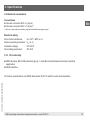
3.6 Operating conditions
Permissible temperature ranges
Medium: see measuring ranges
Ambient: -20 ... +80 °C (-4 ... 176 °F)
1)
Storage: -20 ... +80 °C (-4 ... 176 °F)
1) The permissible ambient temperature is limited to -20 ... +40 °C (-4 ... +104 °F) at medium temperatures above 80 °C (176 °F)
At high medium or ambient temperatures, ensure by suitable measures that the instrument case tempe-
rature does not exceed 80 °C (176 °F) in continuous operation (the temperature is measured at the
hexagon of the process connection).
Humidity
45 ... 75 % r. h.
Vibration resistance
Insertion length F ≤ 150 mm (5.91 in): 6 g (IEC 60068-2-6, under resonance)
Insertion length F ≥ 250 mm (9.84 in): 2 g (IEC 60068-2-6, under resonance)
Shock resistance
50 g (IEC 60068-2-27, mechanical)
Typical response time
T05 < 5 s (per DIN EN 60751)
T09 < 10 s (per DIN EN 60751)
Static operating pressure
Thermowell with xed process connection: max. 150 bar (2,715 psi)
Thermowell with adjustable compression tting: max. 50 bar (725 psi)
1)
1) Only valid with the delivered WIKA compression tting

14 WIKA operating instructions temperature switch, model TSD-30
EN
11613025.04 05/2018 EN/DE/FR/ES
3.Specications
Ingress protection
IP65 and IP67 (per IEC 60529)
The stated ingress protection only applies when plugged in using mating connectors that have the
appropriate ingress protection.
Mounting position
as required
3.7 Reference conditions
Temperature: 15 ... 25 °C (59 ... 77 °F)
Atmospheric pressure: 950 ... 1,050 mbar (13.78 ... 15.23 °F)
Humidity: 45 ... 75 % r. h.
Nominal position: Process connection lower mount (LM)
Power supply: DC 24 V
Load: see “Output signal”
3.8 Materials
Wetted parts
Thermowell: Stainless steel 316Ti
Non-wetted parts
Case: Stainless steel 304
Keyboard: TPE-E
Display window: PC
Display head: PC + ABS-Blend

15WIKA operating instructions temperature switch, model TSD-30
EN
11613025.04 05/2018 EN/DE/FR/ES
3.Specications
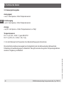
3.9 Electrical connections
Connections
■
Circular connector M12 x 1 (4-pin)
■
Circular connector M12 x 1 (5-pin)
1)
1) Only for version with two switching outputs and additional analogue signal
Electrical safety
Short-circuit resistance: S
+
/ SP1 / SP2 vs. U
-
Reverse polarity protection: U
+
vs. U
-
Insulation voltage: DC 500 V
Overvoltage protection: DC 40 V
3.10 CE conformity
■
EMC directive,
EN 61326 emission (group 1, class B) and interference immunity (industrial
application)
■
RoHS directive
For further specications see WIKA data sheet TE 67.03 and the order documentation.

16 WIKA operating instructions temperature switch, model TSD-30
EN
11613025.04 05/2018 EN/DE/FR/ES
4. Design and function
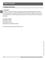
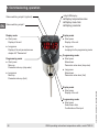
4. Design and function
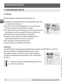
4.1 Description
By means of a measuring element and by supplying power, the prevailing temperature is converted
into a switching signal or an amplied standardised electrical signal via the change in resistance of the
measuring element. This electrical signal varies in proportion to the temperature and can be evaluated
accordingly.
4.2 Scope of delivery
■
Temperature switch
■
Operating instructions
■
Adjustable compression tting (option)
Cross-check scope of delivery with the delivery note.

17WIKA operating instructions temperature switch, model TSD-30
EN
11613025.04 05/2018 EN/DE/FR/ES
5. Transport, packaging and storage
5.1 Transport
Check the temperature switch for any damage that may have been caused by transport.
Obvious damage must be reported immediately.
5.2 Packaging
Do not remove packaging until just before mounting.
Keep the packaging as it will provide optimum protection during transport (e.g. change in installation site,
sending for repair).
5.3 Storage
Permissible conditions at the place of storage:
■
Storage temperature: -20 ... +80 °C
■
Humidity: 45 ... 75 % relative humidity
WARNING!
Before storing the instrument (following operation), remove any residual media. This is of
particular importance if the medium is hazardous to health, e.g. caustic, toxic, carcinogenic,
radioactive, etc.
5. Transport, packaging and storage

18 WIKA operating instructions temperature switch, model TSD-30
EN
11613025.04 05/2018 EN/DE/FR/ES
6. Commissioning, operation
6. Commissioning, operation
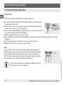
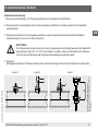
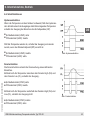
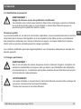
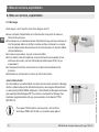
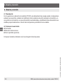
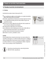
6.1 Mounting
Required tool: Open-ended spanner (spanner width 27)
■
The sealing faces at the temperature switch and the measuring point
always have to be clean.
■
Only ever screw in, or unscrew, the instrument via the spanner ats.
Never use the case as a working surface.
■
The correct torque depends on the dimensions of the process connec-
tion and the sealing used (form/material).
■
When screwing in, do not cross the threads.
■
For information on tapped holes and welding sockets, see Technical Information IN 00.14 at www.
wika.com.
■
The instrument must be earthed via the process connection.
■
Attach the connector and screw it in hand-tight.
Seal
Correct sealing of the process connections with parallel threads at
the sealing face
must be made using suitable at gaskets, sealing
rings or WIKA prole sealings. The sealing of tapered threads (e.g.
NPT threads) is made by providing the thread with additional sealing
material such as, for example, PTFE tape (EN 837-2).
For further information on sealings see WIKA data sheet
AC 09.08 or under www.wika.com.

19WIKA operating instructions temperature switch, model TSD-30
EN
11613025.04 05/2018 EN/DE/FR/ES
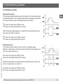
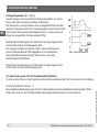
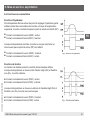
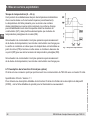
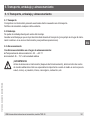
6. Commissioning, operation
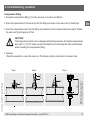
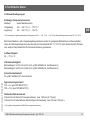
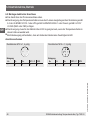
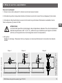
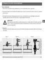
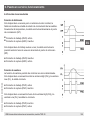
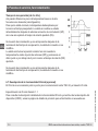
Step 1 Step 2 Step 3
Maintain distance above 80° C
(176 °F) medium temperature
Compressiontting
1. Screw the compression tting (1) into the process connection and tighten.
2. Insert the tapered side of the ferrule (2) into the tting and screw on the union nut (3) hand-tight.
3. Insert the temperature switch into the tting and maintain it at the required immersion depth. Tighten
the union nut (3) with approx. 50 Nm.
CAUTION!
The temperature switch can be damaged at high temperatures. At medium temperatures
above 80° C (176 °F) make sure that the distance to the housing (55 mm) is maintained
when mounting the compression tting.
4. Optional
Check the assembly: Loosen the union nut. The ferrule is rmly connected to the sensor tube.

20 WIKA operating instructions temperature switch, model TSD-30
EN
11613025.04 05/2018 EN/DE/FR/ES
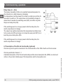
6. Commissioning, operation
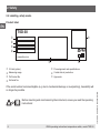
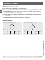
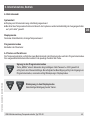
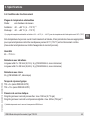
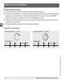
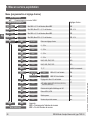
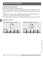
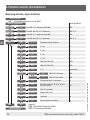
Circular connector M12 x 1, 4-pin
Assignment
U+ U- S+ SP1 / C SP2
1 3 2 4 2
Circular connector M12 x 1, 5-pin
Assignment
U+ U- S+ SP1 / C SP2
1 3 5 4 2
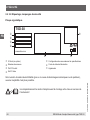
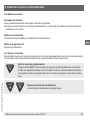
6.2 Making the electrical connection
■
The instrument must be earthed via the process connection.
■
The power supply for the temperature switch must be made via an energy-limited electrical circuit in
accordance with section 9.3 of UL/EN/IEC 61010-1 or an LPS to UL/EN/IEC 60950-1 or class 2 in
accordance with UL1310/UL1585 (NEC or CEC).
■
The power supply must be suitable for operation above 2,000 m should the temperature switch be
used at this altitude.
■
For cable outlets, make sure that no moisture enters at the cable end.
Connection diagramms
La page est en cours de chargement...
La page est en cours de chargement...
La page est en cours de chargement...
La page est en cours de chargement...
La page est en cours de chargement...
La page est en cours de chargement...
La page est en cours de chargement...
La page est en cours de chargement...
La page est en cours de chargement...
La page est en cours de chargement...
La page est en cours de chargement...
La page est en cours de chargement...
La page est en cours de chargement...
La page est en cours de chargement...
La page est en cours de chargement...
La page est en cours de chargement...
La page est en cours de chargement...
La page est en cours de chargement...
La page est en cours de chargement...
La page est en cours de chargement...
La page est en cours de chargement...
La page est en cours de chargement...
La page est en cours de chargement...
La page est en cours de chargement...
La page est en cours de chargement...
La page est en cours de chargement...
La page est en cours de chargement...
La page est en cours de chargement...
La page est en cours de chargement...
La page est en cours de chargement...
La page est en cours de chargement...
La page est en cours de chargement...
La page est en cours de chargement...
La page est en cours de chargement...
La page est en cours de chargement...
La page est en cours de chargement...
La page est en cours de chargement...
La page est en cours de chargement...
La page est en cours de chargement...
La page est en cours de chargement...
La page est en cours de chargement...
La page est en cours de chargement...
La page est en cours de chargement...
La page est en cours de chargement...
La page est en cours de chargement...
La page est en cours de chargement...
La page est en cours de chargement...
La page est en cours de chargement...
La page est en cours de chargement...
La page est en cours de chargement...
La page est en cours de chargement...
La page est en cours de chargement...
La page est en cours de chargement...
La page est en cours de chargement...
La page est en cours de chargement...
La page est en cours de chargement...
La page est en cours de chargement...
La page est en cours de chargement...
La page est en cours de chargement...
La page est en cours de chargement...
La page est en cours de chargement...
La page est en cours de chargement...
La page est en cours de chargement...
La page est en cours de chargement...
La page est en cours de chargement...
La page est en cours de chargement...
La page est en cours de chargement...
La page est en cours de chargement...
La page est en cours de chargement...
La page est en cours de chargement...
La page est en cours de chargement...
La page est en cours de chargement...
La page est en cours de chargement...
La page est en cours de chargement...
La page est en cours de chargement...
La page est en cours de chargement...
La page est en cours de chargement...
La page est en cours de chargement...
La page est en cours de chargement...
La page est en cours de chargement...
La page est en cours de chargement...
La page est en cours de chargement...
La page est en cours de chargement...
La page est en cours de chargement...
La page est en cours de chargement...
La page est en cours de chargement...
La page est en cours de chargement...
La page est en cours de chargement...
La page est en cours de chargement...
La page est en cours de chargement...
La page est en cours de chargement...
La page est en cours de chargement...
La page est en cours de chargement...
La page est en cours de chargement...
La page est en cours de chargement...
La page est en cours de chargement...
-
 1
1
-
 2
2
-
 3
3
-
 4
4
-
 5
5
-
 6
6
-
 7
7
-
 8
8
-
 9
9
-
 10
10
-
 11
11
-
 12
12
-
 13
13
-
 14
14
-
 15
15
-
 16
16
-
 17
17
-
 18
18
-
 19
19
-
 20
20
-
 21
21
-
 22
22
-
 23
23
-
 24
24
-
 25
25
-
 26
26
-
 27
27
-
 28
28
-
 29
29
-
 30
30
-
 31
31
-
 32
32
-
 33
33
-
 34
34
-
 35
35
-
 36
36
-
 37
37
-
 38
38
-
 39
39
-
 40
40
-
 41
41
-
 42
42
-
 43
43
-
 44
44
-
 45
45
-
 46
46
-
 47
47
-
 48
48
-
 49
49
-
 50
50
-
 51
51
-
 52
52
-
 53
53
-
 54
54
-
 55
55
-
 56
56
-
 57
57
-
 58
58
-
 59
59
-
 60
60
-
 61
61
-
 62
62
-
 63
63
-
 64
64
-
 65
65
-
 66
66
-
 67
67
-
 68
68
-
 69
69
-
 70
70
-
 71
71
-
 72
72
-
 73
73
-
 74
74
-
 75
75
-
 76
76
-
 77
77
-
 78
78
-
 79
79
-
 80
80
-
 81
81
-
 82
82
-
 83
83
-
 84
84
-
 85
85
-
 86
86
-
 87
87
-
 88
88
-
 89
89
-
 90
90
-
 91
91
-
 92
92
-
 93
93
-
 94
94
-
 95
95
-
 96
96
-
 97
97
-
 98
98
-
 99
99
-
 100
100
-
 101
101
-
 102
102
-
 103
103
-
 104
104
-
 105
105
-
 106
106
-
 107
107
-
 108
108
-
 109
109
-
 110
110
-
 111
111
-
 112
112
-
 113
113
-
 114
114
-
 115
115
-
 116
116


dans d''autres langues
- español: WIKA TSD-30 Manual de usuario
- Deutsch: WIKA TSD-30 Benutzerhandbuch
Documents connexes
-
WIKA PSA-31 Mode d'emploi
-
-
-
-
-
-
-
WIKA PSD-4-ECO Mode d'emploi
-
-
Autres documents
-
IFM PN3050 Mode d'emploi
-
SICK PBS Manuel utilisateur
-
Franke FNO 605 BK Manuel utilisateur
-
-
-
AVENTICS Capteur de pression PE5 Le manuel du propriétaire
-
Miele UG 413-30 Manuel utilisateur
-
Miele UG500530SS Manuel utilisateur
-
turck TS700 Guide de démarrage rapide
-
turck TS720 Guide de démarrage rapide