
Terra™ 28B
INSTRUCTIONS FOR USE
Advance Model: 908 4702 010 ENGLISH
INSTRUCTIONS D’UTILISATION
Modèle Advance: 908 4702 010 FRANÇAIS
INSTRUCCIONES DE USO
Modelo Advance: 908 4702 010 ESPAÑOL
INSTRUÇÕES DE USO
Modelo Advance: 908 4702 010 PORTUGUÊS
146 3081 000(2)2007-06


INSTRUCTIONS FOR USE ENGLISH
Terra™ 28B 146 3081 000(2)2007-06 1
TABLE OF CONTENTS
INTRODUCTION .........................................................................................................................................................2
MANUAL PURPOSE AND CONTENTS ................................................................................................................. 2
TARGET ................................................................................................................................................................. 2
HOW TO KEEP THIS MANUAL ............................................................................................................................. 2
IDENTIFICATION DATA ......................................................................................................................................... 2
OTHER REFERENCE MANUALS ......................................................................................................................... 3
SPARE PARTS AND MAINTENANCE ................................................................................................................... 3
CHANGES AND IMPROVEMENTS ....................................................................................................................... 3
OPERATION CAPABILITIES .................................................................................................................................. 3
CONVENTIONS ..................................................................................................................................................... 3
UNPACKING/DELIVERY ............................................................................................................................................3
SAFETY ......................................................................................................................................................................4
SYMBOLS .............................................................................................................................................................. 4
GENERAL INSTRUCTIONS .................................................................................................................................. 4
MACHINE DESCRIPTION ..........................................................................................................................................6
MACHINE STRUCTURE AND CONTROLS .......................................................................................................... 6
MACHINE STRUCTURE AND CONTROLS - DESCRIPTION .............................................................................. 7
ACCESSORIES/OPTIONS .................................................................................................................................... 8
WIRING DIAGRAM ................................................................................................................................................ 9
USE ...........................................................................................................................................................................10
BATTERY CHECK ON A NEW MACHINE ........................................................................................................... 10
BEFORE MACHINE START-UP ........................................................................................................................... 10
STARTING AND STOPPING THE MACHINE ...................................................................................................... 10
MACHINE OPERATION ....................................................................................................................................... 11
HOPPER EMPTYING .......................................................................................................................................... 11
AFTER MACHINE USE ........................................................................................................................................ 11
MACHINE LONG INACTIVITY ............................................................................................................................. 11
FIRST PERIOD OF USE ...................................................................................................................................... 11
MAINTENANCE ........................................................................................................................................................12
SCHEDULED MAINTENANCE TABLE ................................................................................................................ 12
BATTERY CHARGER CABLE CHECK ................................................................................................................ 12
SIDE BROOM HEIGHT CHECK AND ADJUSTMENT .........................................................................................13
SIDE BROOM DISASSEMBLY/ASSEMBLY ........................................................................................................ 13
MAIN BROOM HEIGHT CHECK AND ADJUSTMENT ........................................................................................ 14
MAIN BROOM DISASSEMBLY/ASSEMBLY ........................................................................................................ 15
DUST FILTER CLEANING AND INTEGRITY CHECK, HOPPER GASKET CHECK ........................................... 16
SKIRT HEIGHT AND OPERATION CHECK......................................................................................................... 17
BATTERY CHARGING ......................................................................................................................................... 17
TROUBLESHOOTING ..............................................................................................................................................18
SCRAPPING .............................................................................................................................................................18

ENGLISH INSTRUCTIONS FOR USE
2146 3081 000(2)2007-06 Terra™ 28B
INTRODUCTION
NOTE
The numbers in brackets refer to the components shown in Machine Description chapter.
MANUAL PURPOSE AND CONTENTS
The purpose of this Manual is to provide the operator with all necessary information to use the machine properly, in a safe
and autonomous way. It contains information about technical data, safety, operation, storage, maintenance, spare parts and
disposal.
Before carrying out any procedure on the machine, the operators and qualifi ed technicians must read this Manual carefully.
Contact Nilfi sk-Advance in case of doubts regarding the interpretation of the instructions and for any further information.
TARGET
This Manual is intended for operators and technicians qualifi ed to perform the machine maintenance.
The operators must not carry out procedures reserved for qualifi ed technicians. Nilfi sk-Advance will not be responsible for
damages coming from the non-observance of this prohibition.
HOW TO KEEP THIS MANUAL
The Instructions for use Manual must be kept near the machine, inside an adequate case, away from liquids and other
substances that can cause damage to it.
IDENTIFICATION DATA
The machine model and serial number are marked on the plate (33).
The machine model year is shown after the Date Code on the serial plate (A07 means January 2007).
This information is useful when requiring machine spare parts. Use the following table to write down the machine identifi cation
data.
MACHINE model ...............................................................................
MACHINE serial number ...................................................................

INSTRUCTIONS FOR USE ENGLISH
Terra™ 28B 146 3081 000(2)2007-06 3
OTHER REFERENCE MANUALS
Spare Parts List (supplied with the machine)
Service Manual (that can be consulted at Nilfi sk-Advance Service Centers)
SPARE PARTS AND MAINTENANCE
All necessary operating, maintenance and repair procedures must be carried out by qualifi ed personnel or by Nilfi sk-Advance
Service Centers. Only original spare parts and accessories must be used.
Contact Nilfi sk-Advance for service or to order spare parts and accessories, specifying the machine model and serial number.
CHANGES AND IMPROVEMENTS
Nilfi sk-Advance constantly improves its products and reserves the right to make changes and improvements at its discretion
without being obliged to apply such benefi ts to the machines that were sold previously.
Any change and/or addition of accessory must be approved and performed by Nilfi sk-Advance.
OPERATION CAPABILITIES
This sweeper has been designed and built to clean (by sweeping and vacuuming) smooth and solid fl oors, in civil and industrial
environments and to collect dust and light debris under safe operation conditions by a qualifi ed operator.
CONVENTIONS
Forward, backward, front, rear, left or right are intended with reference to the operator’s position, that is to say with the hands on
the handlebar (6).
UNPACKING/DELIVERY
When the machine is delivered, check that the packing and the machine were not damaged during transportation. In case of
visible damages, keep the packing and have it checked by the Carrier that delivered it. Call the Carrier immediately to fi ll in a
damage claim.
Check that the machine is equipped with the following features:
Technical documents:
Sweeper Instructions for use Manual
Sweeper Spare Parts List
No. 1 vacuum system motor fuse
–
–
–
•
•
•

ENGLISH INSTRUCTIONS FOR USE
4146 3081 000(2)2007-06 Terra™ 28B
SAFETY
The following symbols indicate potentially dangerous situations. Always read this information carefully and take all necessary
precautions to safeguard people and property.
The operator's cooperation is essential in order to prevent injury. No accident prevention program is effective without the total
cooperation of the person responsible for the machine operation. Most of the accidents that may occur in a factory, while
working or moving around, are caused by failure to comply with the simplest rules for exercising prudence. A careful and prudent
operator is the best guarantee against accidents and is essential for successful completion of any prevention program.
SYMBOLS
DANGER!
It indicates a dangerous situation with risk of death for the operator.
WARNING!
It indicates a potential risk of injury for people.
CAUTION!
It indicates a caution or a remark related to important or useful functions.
Pay particular attention to the paragraphs marked by this symbol.
NOTE
It indicates a caution or a remark related to important or useful functions.
CONSULTATION
It indicates the necessity to refer to the Instructions for use Manual before performing any procedure.
GENERAL INSTRUCTIONS
Specifi c warnings and cautions to inform about potential damages to people and machine are shown below.
DANGER!
Before performing any maintenance/repair procedure, turn the main switch to "0" and, if necessary,
disconnect the battery.
This machine must be used by properly trained and authorised personnel only. Children or disabled
people cannot use this machine.
Keep the battery away from sparks, fl ames and incandescent material.
Do not wear jewelry when working near electrical components.
Do not work under the lifted machine without supporting it with safety stands.
Do not operate the machine near toxic, dangerous, fl ammable and/or explosive powders, liquids or
vapors.
–
–
–
–
–
–

INSTRUCTIONS FOR USE ENGLISH
Terra™ 28B 146 3081 000(2)2007-06 5
WARNING!
Before using the battery charger, ensure that frequency and voltage values, indicated on the machine
serial number plate, match the electrical mains voltage.
Do not pull or carry the machine by the battery charger cable and never use the battery charger cable
as a handle. Do not close a door on the battery charger cable, or pull the battery charger cable around
sharp edges or corners. Do not run the machine on the battery charger cable.
Keep the battery charger cable away from heated surfaces.
Do not charge the batteries if the battery charger cable or the plug are damaged. If the battery charger
cable is damaged, contact Nilfi sk-Advance Service Center.
To reduce the risk of fi re, electric shock, or injury, do not leave the machine unattended when it is
plugged in. Before performing any maintenance procedure, disconnect the battery charger cable from
the electrical mains.
If the machine is not working as it should, has been damaged, left outdoors or dropped into water, return
it to Nilfi sk-Advance Service Center.
Do not smoke while charging the batteries.
Always protect the machine against the sun, rain and bad weather, both under operation and inactivity
condition. Store the machine indoors, in a dry place.
Do not allow to be used as a toy. Close attention is necessary when used near children.
Use only as shown in this Manual. Use only Nilfi sk-Advance's recommended accessories.
Take all necessary precautions to prevent hair, jewelry and loose clothes from being caught by the
machine moving parts.
Do not leave the machine unattended if the main switch is not turned to "0" and without being sure that
it cannot move independently.
Do not use the machine on slopes with a gradient exceeding the specifi cations.
Do not wash the machine with direct or pressurised water jets, or with corrosive substances. Do not use
compressed air to clean this type of machine.
While using this machine take care not to cause harm to other people, and children especially.
The machine storage temperature must be between +32°F and +104°F (0°C and +40°C).
The machine working temperature must be between +32°F and +104°F (0°C and +40°C).
The humidity must be between 30% and 95%.
Do not use the machine as a means of transport.
Do not use the machine on slopes with a gradient exceeding the specifi cations.
Do not allow the brooms to operate while the machine is stationary to avoid damaging the fl oor.
In case of fi re, possibly use a powder fi re extinguisher, not a water one.
Do not bump into shelves or scaffoldings, especially where there is a risk of falling objects.
Adjust the operation speed to suit the fl oor conditions.
This machine cannot be used on roads or public streets.
Do not remove or modify the plates affi xed to the machine.
Do not tamper with the machine safety guards and follow the ordinary maintenance instructions
scrupulously.
If the machine is used according to the instructions, the vibrations are not dangerous. The machine
vibration level is less than 98.4 in/s2 (2.5 m/s2) (98/37/EEC-EN 1033/1995).
Use only brooms supplied with the machine and those specifi ed in the Instructions for use Manual.
Using other brooms could reduce safety.
In case of machine malfunctions, ensure that these are not due to lack of maintenance. Otherwise,
request assistance from the authorised personnel or from an authorised Service Center.
Carefully read all the instructions before carrying out any maintenance/repair procedure.
To ensure machine proper and safe operation, the scheduled maintenance shown in the relevant chapter
of this Manual must be performed by the authorised personnel or by an authorised Service Center.
If parts must be replaced, require ORIGINAL spare parts from a Dealer or Authorised Retailer.
The machine must be disposed of properly, because of the presence of toxic-harmful materials
(batteries, plastics, etc.), which are subject to standards that require disposal in special centers (see the
Scrapping chapter).
–
–
–
–
–
–
–
–
–
–
–
–
–
–
–
–
–
–
–
–
–
–
–
–
–
–
–
–
–
–
–
–
–
–

ENGLISH INSTRUCTIONS FOR USE
6146 3081 000(2)2007-06 Terra™ 28B
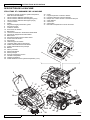
MACHINE DESCRIPTION
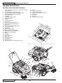
MACHINE STRUCTURE AND CONTROLS
Main switch for vacuum system, main broom and side
broom activation
Charged battery warning light (green)
Semi-discharged battery warning light (yellow)
Discharged battery warning light (red)
Drive control lever
Handlebar
Handlebar adjusting knobs
Filter shaker knob
Hopper
Front steering wheel
Side broom
Side broom lifting/lowering lever
Side broom height adjusting knob
Main broom
Main broom height adjusting knobs
Rear driving wheels
Can holder
Battery charger cable
Battery charger cable housing
Side broom motor circuit breaker
Main motor circuit breaker
Battery
Dust fi lter
Side broom motor
Main motor
Drive system gear
Vacuum fan
Battery charger
Vacuum system motor lamellar fuse (7.5 A)
1.
2.
3.
4.
5.
6.
7.
8.
9.
10.
11.
12.
13.
14.
15.
16.
17.
18.
19.
20.
21.
22.
23.
24.
25.
26.
27.
28.
29.
Hood
Hopper upper handle
Hopper lower handles
Serial number plate/technical data
Side skirts
Front skirt
Rear skirt
Drive system belt adjuster
30.
31.
32.
33.
34.
35.
36.
37.
S311348
5
6
7
17
31
8
14
7
30 36 9
11
32
29
10
34
13
16
15
12
34
35
15
16
23 24
25
27
22
28
26
37
37
18
20
19
33
21
1
2
3
4

INSTRUCTIONS FOR USE ENGLISH
Terra™ 28B 146 3081 000(2)2007-06 7
MACHINE STRUCTURE AND CONTROLS - DESCRIPTION
Main switch for vacuum system, main broom and side broom activation (1) – When turned to “0” the machine is off; when
turned to “I” the vacuum system and main broom are turned on; when turned to “II”, the vacuum system, main broom and side
broom are turned on.
Green warning light (2) – When it is on and the machine is running, it indicates that the batteries are charged. Residual
autonomy depends on battery capacity and working conditions. When it is on and the batteries are charging, it means that the
charging cycle has been completed and the batteries are charged.
Yellow warning light (3) – When it is on and the machine is running, it indicates that the batteries are semi-discharged.
Residual autonomy is 10 minutes approximately. When it is on and the batteries are charging, it means that the charging cycle is
nearly completed and the batteries are nearly charged.
Red warning light (4) – When it is on and the machine is running, it indicates that the batteries are discharged. The autonomy
is over, the batteries must be recharged (see the procedure in the relevant paragraph). When it is on and the batteries are
charging, it means that the charging cycle is in progress.
Drive control lever (5) – When pulling it gradually towards the handlebar, the machine starts. Drive speed is increased by
pulling the lever further.
Handlebar (6) – Grasp it and use it to manoeuver the machine.
Handlebar adjusting knobs (7) – Loosen the knobs and adjust the handlebar tilting, then tighten the knobs.
Filter shaker knob (8) – By moving it to right and then to the left several times, the fi lter is shaken; perform this procedure
periodically while sweeping in order to keep the vacuum system effi cient. Before turning on the fi lter shaker, stop the machine
and turn the main switch (1) to "0".
Hopper (9) – It collects swept and vacuumed debris. When it is full, it must be emptied according to the procedure shown in Use
chapter. When the hopper is removed, all machine functions are disabled.
Front caster wheel (10) – It allows the machine to turn.
Side broom (11) – It removes dust and debris on the machine front right end side (along footpaths, walls, etc.) and it conveys it
toward the main broom.
Side broom lifting/lowering lever (12) – Disengage it from the slot, then push it forward to lower the side broom and pull it
backwards to lift it.
Side broom height adjusting knob (13) – It adjusts the side broom height from the ground (see the procedure in the
Maintenance chapter).
Main broom (14) – It removes and collects dust and debris, which are then vacuumed into the hopper.
Main broom height adjusting knobs (15) – They adjust the main broom height from the ground (see the procedure in the
Maintenance chapter).
Rear driving wheels (16) – They push the machine forward while sweeping.
Can holder (17) – Compartments to store a can or small objects.
Battery charger cable (18) – It is used to charge the batteries (see the procedure in the Maintenance chapter).
Battery charger cable housing (19) – Store the battery charger cable in this compartment when not in use.
Side broom motor circuit breaker (20) – It activates to protect the side broom motor in case of overload. If the circuit breaker
activates, wait for the motor to cool down, then reset the circuit breaker by pushing it inward, until the end-of-stroke.
30 A main motor circuit breaker (21) – It activates to protect the main motor in case of overload. If the circuit breaker
activates, wait for the motor to cool down, then reset the circuit breaker by pushing it inward, until the end-of-stroke.
Batteries (22) – They supply current for machine operation. The batteries are GEL type, without liquid electrolyte and do not
require maintenance.
Dust fi lter (23) – It retains swept and vacuumed dust and it allows the air to pass. While sweeping it is necessary to move the
fi lter shaker knob (8) periodically to remove the dust deposits on the fi lter, thus granting the vacuum system effi ciency.
Side broom motor (24) – It drives the side broom.
Main motor (25) – It drives the main broom and the drive system.
Drive system gear (26) – It supplies the drive force to the wheels.
Vacuum fan (27) – It vacuums dust and debris from the ground.
Battery charger (28) – It charges the batteries (see the procedure in the Maintenance chapter).
7.5 A vacuum system motor lamellar fuse (29) – It opens to protect the vacuum system motor in case of overload. If there is
an open, the fuse must be replaced by the authorised personnel.
Hood (30) – It protects the inner components of the machine.
Hopper handles (31) and (32) – These allow to grasp the hopper and handle it.
Serial number plate/technical data/conformity certifi cation (33) – It contains the machine data.
Side, front and rear skirts (34), (35), (36) – They increase the vacuuming effect for dust and debris collection.

ENGLISH INSTRUCTIONS FOR USE
8146 3081 000(2)2007-06 Terra™ 28B
ACCESSORIES/OPTIONS
In addition to the standard components, the machine can be equipped with the following accessories/options, according to the
machine specifi c use.
NOTE
For further information concerning the optional accessories, contact an authorised Dealer.
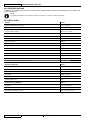
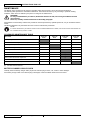
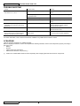
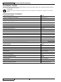
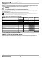
TECHNICAL DATA
General Values
Cleaning width (without side broom) 19.7 in (500 mm)
Cleaning width (with side broom) 28.3 in (720 mm)
Machine size with folded handlebar and without side broom
(Length x Width x Height)
39.3 x 31.4 x 24.4 in
(998 x 797 x 501 mm)
Minimum height from the ground (skirts not included) 1.0 in (25 mm)
Main broom size (diameter x length) 7.9 x 19.7 in (200 x 500 mm)
Side broom diameter 12.4 in (315 mm)
Main broom speed 335 rpm
Side broom speed 100 rpm
Gradeability 2%
Hopper capacity 15.8 US Gal (60 litres)
Total machine weight (with standard battery) 172 lbs (78 kg)
Front steering wheel size (diameter x length) 3.0 x 1.3 in (75 x 32 mm)
Rear wheel size (diameter x length) 11.8 x 1.8 in (300 x 45 mm)
Maximum drive speed 2.3 mph (3.7 km/h)
Sound pressure level at the operator's hear (A Lpa) 59.3 dB(A)
Electrical components Values
Electrical system voltage 12 V
Standard battery GEL, 12 V, 80 Ah
Battery charger 6 A
Main motor 200 W, 1,500 rpm
Side broom motor 40 W
Vacuum system motor 50 W
Dust vacuuming and fi ltering Values
Dust fi lter 5–10 μm (polyester)
Dust fi lter surface 10.8 ft2 (1 m2)
Main broom compartment vacuum 0.47 in H2O (12 mm H2O)

INSTRUCTIONS FOR USE ENGLISH
Terra™ 28B 146 3081 000(2)2007-06 9
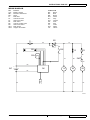
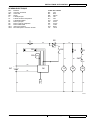
WIRING DIAGRAM
BAT: Batteries
CH1: Battery charger
EB1: Electronic board LED
ES1: Relay
F1: Main fuse
F2: Vacuum fan fuse
F3: Side broom fuse
M1: Main motor
M2: Vacuum system motor
M3: Side broom motor
SW1: Main switch
SW2: Hopper microswitch
Colour code
BK: Black
BU: Blue
BN: Brown
GN: Green
GY: Grey
OG: Orange
PK: Pink
RD: Red
VT: Violet
WH: White
YE: Yellow
S311349
BAT
F1
M1 M2
ES1
CH1
F2
EB1
J1.1
RD
RD
OG
GY BN
RD
BK
BK
BKBK
WH
VT
SW2
OG
J1.2
J1.3
J1.4
J1.5
J1.6
J1.7
J1.8
BK
M3
F3
BU
GY
1
SW1a
SW1b
BU
I
II
II
I
-
+
R
R

ENGLISH INSTRUCTIONS FOR USE
10 146 3081 000(2)2007-06 Terra™ 28B
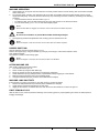
USE WARNING!
On some points of the machine there are some adhesive plates indicating:
DANGER
WARNING
CAUTION
NOTE
–
–
–
–
While reading this Manual, the operator must pay particular attention to the symbols shown on the plates.
Do not cover these plates for any reason and immediately replace them if they are damaged.
BATTERY CHECK ON A NEW MACHINE
The machine is supplied with a standard 12 V, 77 Ah GEL battery (which does not require maintenance).
BEFORE MACHINE START-UP
Make sure that there are no open doors/hoods and that the machine is in normal operating conditions.
If the machine has not been used after being transported, check that all the blocks used for the transportation have been
removed.
Check that side and main broom are installed, otherwise install them (see the procedure in the Maintenance chapter).
STARTING AND STOPPING THE MACHINE
Starting the machine
Adjust the handlebar (6) to reach a comfortable position, by loosening the knobs (7).
When the adjustment is completed, tighten the knobs.
To use the main broom only (14), turn the main switch (1) to “I”.
To use also the side broom (11), turn the main switch (1) to “II”, then lower the side broom by disengaging the lever (12)
and by pushing it forward.
Check that the green warning light (2) (charged battery) turns on.
If the yellow or red warning light (3 or 4) turns on, turn the main switch (1) back to “0” and charge the batteries (see the
procedure in the Maintenance chapter).
NOTE
The side broom (11) can be lifted and lowered even if it is turned on.
Start sweeping by grasping the handlebar (6) and pulling the drive control lever (5) gradually.
Stopping the machine
Release the drive control lever (5) to stop the drive system.
Turn off the vacuum system and the brooms, by turning the main switch (1) to “0”.
Lift the side broom (11) by pulling the lever (12) backwards and by engaging it into the storage slot.
1.
2.
3.
1.
2.
3.
1.
2.
3.

INSTRUCTIONS FOR USE ENGLISH
Terra™ 28B 146 3081 000(2)2007-06 11
MACHINE OPERATION
Avoid stopping for a long time with the machine in the same position and the brooms rotating: this could create unwanted
marks on the fl oor.
For machine proper operation, the dust fi lter must be as clean as possible. Therefore the fi lter shaker must be used at
regular intervals (every 10 minutes, but this interval may vary according to the fl oor conditions), according to the following
procedure.
Stop the machine and turn the main switch (1) to “0”.
To shake the fi lter, move the fi lter shaker knob (8) to the right and then to the left several times.
Turn the main switch (1) to “I” or to “II” and start sweeping again.
NOTE
When the dust fi lter is clogged, the machine cannot collect dust and debris anymore.
CAUTION!
Do not work on wet fl oors to prevent the dust fi lter from being damaged.
The hopper (9) should be emptied after each working cycle and whenever it is full.
NOTE
When the hopper is full, the machine cannot collect dust and debris anymore.
HOPPER EMPTYING
Stop the machine and turn the main switch (1) to "0".
Remove the hopper (9) by using the handles (31) and (32), then empty it at the waste collection center.
Then install the hopper.
The machine is ready to start working again.
NOTE
When the hopper is removed, all machine functions are disabled.
AFTER MACHINE USE
After working, before leaving the machine:
Turn the main switch (1) to “0”.
Clean the fi lter by using the fi lter shaker (8).
Empty the hopper (9) (see the procedure in the previous paragraph).
Lift the side broom (11) by pulling the lever (12) backwards and by engaging it to the fastener.
Make sure that the machine cannot move independently.
Charge the batteries (see the procedure in the Maintenance chapter).
MACHINE LONG INACTIVITY
If the machine is not going to be used for more than 30 days, proceed as follows:
Perform the daily maintenance procedures (see the Maintenance chapter).
Check that the machine storage area is dry and clean.
Slightly lift the machine so that the skirts, the main broom and the wheels do not touch the ground.
FIRST PERIOD OF USE
After the fi rst 8 hours, check the machine fastening and connecting parts for proper tightening and check the visible parts for
integrity and leakage.
1.
2.
•
•
•
3.
1.
2.
3.
4.
5.
6.
1.
2.
3.

ENGLISH INSTRUCTIONS FOR USE
12 146 3081 000(2)2007-06 Terra™ 28B
MAINTENANCE
The lifespan of the machine and its maximum operating safety are ensured by correct and regular maintenance.
The following table provides the scheduled maintenance. The intervals shown may vary according to particular working
conditions, which are to be defi ned by the person in charge of the maintenance.
WARNING!
To carry out maintenance procedures, the machine must be off and, if necessary, the batteries must be
disconnected.
Moreover, carefully read the instructions in the Safety paragraph.
All scheduled or extraordinary maintenance procedures must be performed by qualifi ed personnel, or by an authorised Service
Center.
This Manual describes only the easiest and most common maintenance procedures.
NOTE
For other maintenance procedures shown in the Scheduled Maintenance Table, refer to the Service Manual that can
be consulted at any Service Center.
SCHEDULED MAINTENANCE TABLE
Procedure Every 10
hours Every 50
hours Every 200
hours Every 400
hours
Battery charger cable check
Side and main broom height check and adjustment
Skirt height and operation check
Dust fi lter cleaning and integrity check
Hopper gasket check
Filter shaker operation check (*)
Drive belt and clutch visual inspection (*)
Drive system belt tensioner adjustment (*)
Nut and screw tightening check (*) (1)
Motor carbon brush check or replacement (*)
(*): For the relevant procedure, see the Service Manual.
(1): And after the fi rst 8 hours.
BATTERY CHARGER CABLE CHECK
Carefully check the battery charger cable (18) and the relevant plug for wear, cuts, cracks or other damages.
If the battery charger cable or the relevant plug is damaged, contact the Nilfi sk-Advance Service Center.

INSTRUCTIONS FOR USE ENGLISH
Terra™ 28B 146 3081 000(2)2007-06 13
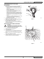
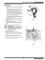
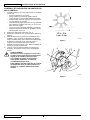
SIDE BROOM HEIGHT CHECK AND
ADJUSTMENT
Check that the side broom is at the correct height from
the ground, according to the following procedure:
Drive the machine on a level ground and lower the
side broom.
Keep the machine stationary and turn on the side
broom for a few seconds.
Turn off the side broom by pressing the switch (1),
then lift it and move the machine.
Check if the size and orientation of the print left by
the side broom are as shown in the fi gure (A, Fig. 1):
the side broom must touch the ground along a circle
arc ranging from "10 o'clock" position to "3 o'clock"
position.
If the print is not within specifi cations, it is necessary
to adjust the broom height, according to the
procedure shown in step 2.
Turn the knob (13) clockwise or counter-clockwise to
adjust the broom height up or down.
Perform step 1 again to check that the side broom is at
the correct height from the ground.
When the broom is too worn and can no longer be
adjusted, replace it according to the procedure shown in
the following paragraph.
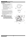
SIDE BROOM DISASSEMBLY/ASSEMBLY
CAUTION!
It is advisable to use protective gloves when
replacing the side broom because there can be
sharp debris between the bristles.
Drive the machine on a level ground.
Turn the main switch (1) to “0”.
Lift the side broom.
Loosen the knob (A, Fig. 2) inside the side broom, then
remove the broom (B) by disengaging it from the pins
(C).
Install the new broom on the machine engaging it on the
pins (C), then tighten the knob (A).
Adjust the height of the new broom according to the
procedure shown in the previous paragraph.
1.
•
•
•
•
•
2.
3.
4.
1.
2.
3.
4.
5.
6.
BC
A
S311350
Figure 1
S311351
Figure 2
10
3

ENGLISH INSTRUCTIONS FOR USE
14 146 3081 000(2)2007-06 Terra™ 28B
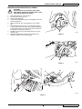
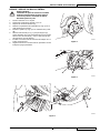
MAIN BROOM HEIGHT CHECK AND
ADJUSTMENT
Check that the main broom is at the correct height from
the ground, according to the following procedure:
Drive the machine on a level ground.
Keep the machine stationary and turn on the main
broom for a few seconds.
Turn off the main broom by pressing the switch (1),
then move the machine.
Check that the main broom print (A, Fig. 3), along its
length, is 1.2-2 in (3-5 cm) wide.
If the print is not within specifi cations, it is necessary
to adjust the broom height, according to the
procedure shown in step 2.
Turn the main switch (1) to “0”.
On both sides of the machine, loosen the knob (A, Fig.
4).
Grasp the support (B) on the points (C) and move it
upwards, then lift it or lower it to change the main broom
height. For height variation, refer to the indicator (D).
Then tighten the knob (A) on both sides of the machine.
Perform step 1 again to check that the main broom is at
the correct height from the ground.
When the broom is too worn and can no longer be
adjusted, replace it according to the procedure shown in
the following paragraph.
CAUTION!
An excessive print (larger than 2 in (5 cm))
of the main broom can lead to machine
malfunction and overheating of moving and
electric parts, thus reducing machine life.
Pay careful attention when performing the
above-mentioned checks, and always use the
machine according to the indicated conditions.
1.
•
•
•
•
•
2.
3.
4.
5.
6.
S311352
Figure 3
S311353
Figure 4
B
A
C
C
D

INSTRUCTIONS FOR USE ENGLISH
Terra™ 28B 146 3081 000(2)2007-06 15
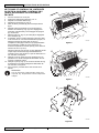
MAIN BROOM DISASSEMBLY/ASSEMBLY
CAUTION!
It is advisable to use protective gloves when
replacing the main broom because there can be
sharp debris between the bristles.
Drive the machine on a level ground.
Turn the main switch (1) to “0”.
Remove the hopper (9).
Loosen the handwheels (A, Fig. 5) completely on the left
side of the machine.
Remove the lid (A, Fig. 6) by grasping it on the points
(B).
Grasp the main broom (A, Fig. 7) on the points (B) and
(C), then disconnect it from the drive hub (D) by pulling it
in the direction shown by the arrow (E); then remove it in
the direction shown by the arrow (F).
Install the new broom by performing steps 3 to 6 in the
reverse order.
Adjust the height of the new broom according to the
procedure shown on the previous page.
1.
2.
3.
4.
5.
6.
7.
8.
S311354
Figure 5
S311355
Figure 6
S311356
Figure 7
A
AB
D
A
C
B
F
E

ENGLISH INSTRUCTIONS FOR USE
16 146 3081 000(2)2007-06 Terra™ 28B
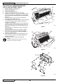
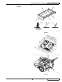
DUST FILTER CLEANING AND INTEGRITY
CHECK, HOPPER GASKET CHECK
Drive the machine on a level ground.
Turn the main switch (1) to “0”.
Remove the hopper (9).
Loosen the knobs (A, Fig. 8).
Grasp the dust fi lter (B) as shown in the fi gure.
Remove the dust fi lter by turning it in the direction shown
by the arrow (A, Fig. 9) to disengage it from the pins (B),
then lower the fi lter to disengage it from the fi lter shaker
combs (C).
Remove the fi lter (A, Fig. 10) from the frame (B) by
disengaging the 2 rubber bands (C).
In an appropriate outdoor area, clean the fi lter by shaking
it on a level and clean surface, tapping the side (D)
opposite to the gasket (E).
Complete the cleaning procedure by using compressed
air (F) at maximum 87.0 psi (6 Bars), blowing only from
the side of the gasket (E), at a minimum distance of 11.8
in (30 cm).
Do not use water or detergents to clean it, otherwise it
can be damaged.
Check the fi lter body for tears. If necessary, replace it.
Clean the bearing surface of the fi lter rubber gasket
(E) and check it for integrity and sealing capabilities. If
necessary, replace the fi lter.
Clean the bearing surface of the hopper gasket (D, Fig.
9) and check it for integrity and sealing capabilities. If
necessary, replace it.
Assemble in the reverse order of disassembly.
NOTE
Assemble the fi lter with the gasket (E, Fig. 10)
positioned as shown in the fi gure.
1.
2.
3.
4.
5.
6.
7.
8.
9.
10.
11.
S311357
Figure 8
S311358
Figure 9
S311359
Figure 10
A
B
A
B
B
D
A C
E
D
F
AB
C
C

INSTRUCTIONS FOR USE ENGLISH
Terra™ 28B 146 3081 000(2)2007-06 17
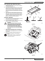
SKIRT HEIGHT AND OPERATION CHECK
Drive the machine on a level ground that is suitable for
checking the skirt height.
Turn the main switch (1) to “0”.
Check that the height from the ground of the side skirts
(A and B, Fig. 11) is within 0 and 0.08 in (0 and 2 mm).
Check the skirts for integrity, cuts or tears, which can
reduce the machine vacuum capabilities. If necessary
replace the side skirts (see the procedure in the Service
Manual).
Check that the front and rear skirts (C and D, Fig. 11)
slightly rub on the ground. Check the skirts for integrity,
cuts or tears, which can reduce the machine vacuum
capabilities. Note that the front skirt has typical vertical
cuts (E). If necessary replace the front and rear skirts
(see the procedure in the Service Manual).
BATTERY CHARGING
Drive the machine to the appointed recharging area and
ensure that it cannot move independently.
Turn the main switch (A, Fig. 12) to "0".
Remove the battery charger cable (B) from the housing
(C) and connect it to the electrical mains.
CAUTION!
Before connecting the battery charger (B),
ensure that frequency and voltage values,
indicated on the machine serial number plate
(33), match the electrical mains voltage.
In case of doubt, do not connect the plug to
the electrical mains, but contact the qualifi ed
personnel.
While charging the batteries, the red warning light (D)
and the yellow warning light (E) turn on in sequence.
When the green warning light (F) turns on, the batteries
are charged.
Disconnect the battery charger cable (B) from the
electrical mains and place it in the housing (C).
NOTE
When the battery charger is connected to the
electrical mains, all machine functions are
automatically disabled.
1.
2.
3.
4.
1.
2.
3.
4.
5.
S311360
Figure 11
S311361
Figure 12
A
D
B
E
C
C
D
A-B
0-2 mm
0-0.08 in
B
C
A
F
E
D

ENGLISH INSTRUCTIONS FOR USE
18 146 3081 000(2)2007-06 Terra™ 28B
TROUBLESHOOTING
Trouble Possible cause Remedy
The machine does not start when turning the
main switch to “I” or to "II".
There is an open in a breaker (21). Reset the breaker by pressing the relevant
button.
The battery charger cable is connected to
the electrical mains.
Disconnect it and place it in the housing.
The batteries are discharged. Charge the batteries.
The side broom does not operate. There is an open in a breaker (20). Reset the breaker by pressing the relevant
button.
The machine operates only when stationary,
otherwise it turns off and the red warning
light fl ashes.
The batteries are discharged. Charge the batteries. If the trouble persists,
have the batteries replaced at Nilfi sk-
Advance Service Center.
The battery autonomy is low. The batteries are dead. Have the batteries replaced at Nilfi sk-
Advance Service Center.
The batteries do not charge: the red warning
light (4) does not turn on when the plug is
inserted in the electrical mains socket.
There is no power supply at the electrical
mains socket.
Check the electrical mains socket by trying
to connect another domestic appliance.
For further information, refer to the Service Manual, available at any Nilfi sk-Advance Service Center.
SCRAPPING
Have the machine scrapped by a qualifi ed scrapper.
Before scrapping the machine, remove and separate the following materials, which must be disposed of properly according to
the Law in force:
Battery
Brooms
Plastic hoses and components
Electrical and electronic components (*)
(*) Refer to the nearest Nilfi sk-Advance Center especially when scrapping electrical and electronic components.
–
–
–
–
La page est en cours de chargement...
La page est en cours de chargement...
La page est en cours de chargement...
La page est en cours de chargement...
La page est en cours de chargement...
La page est en cours de chargement...
La page est en cours de chargement...
La page est en cours de chargement...
La page est en cours de chargement...
La page est en cours de chargement...
La page est en cours de chargement...
La page est en cours de chargement...
La page est en cours de chargement...
La page est en cours de chargement...
La page est en cours de chargement...
La page est en cours de chargement...
La page est en cours de chargement...
La page est en cours de chargement...
-
 1
1
-
 2
2
-
 3
3
-
 4
4
-
 5
5
-
 6
6
-
 7
7
-
 8
8
-
 9
9
-
 10
10
-
 11
11
-
 12
12
-
 13
13
-
 14
14
-
 15
15
-
 16
16
-
 17
17
-
 18
18
-
 19
19
-
 20
20
-
 21
21
-
 22
22
-
 23
23
-
 24
24
-
 25
25
-
 26
26
-
 27
27
-
 28
28
-
 29
29
-
 30
30
-
 31
31
-
 32
32
-
 33
33
-
 34
34
-
 35
35
-
 36
36
-
 37
37
-
 38
38


dans d''autres langues
- English: Nilfisk Terra 28B User manual
Documents connexes
Autres documents
-
Nilfisk-ALTO SW 750 Manuel utilisateur
-
-
-
 Nilfisk-Advance America Terra 5200B Manuel utilisateur
-
Alto FLOORTEC R 570 B Manuel utilisateur
-
-
Nilfisk-Advance CR 1200 Instructions For Use Manual
-
