
Need help? Visit Sauder.com to view video assembly tips or chat with a live rep.
Prefer the phone? Call 1-800-523-3987.
Share your journey!
sauder.com
NOTE: THIS INSTRUCTION
BOOKLET CONTAINS IMPORTANT
SAFETY INFORMATION.
PLEASE READ AND KEEP FOR
FUTURE REFERENCE.
Enlish p 1-22
Français p 23-25
Español p 26-28
Lot # 373325 05/26/15
Purchased: __________________
Be sure to ive us a rin before
makin any returns. 1-800-523-3987
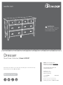
Dresser
Shoal Creek Collection | Model 409937
WARNING
CHOKING HAZARD - Small Parts
Not for children under 3 years.
Adult assembly required.

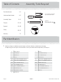
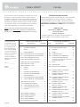
Table of Contents Assembly Tools Required
Part Identifi cation
Hardware Identifi cation
Assembly Steps
Français
Español
Safety
Warranty
Hammer
Not actual size
No. 2 Phillips Screwdriver
Tip Shown Actual Size
2-3
4-5
6-22
23-25
26-28
29-30
31
409937 www.sauder.com/servicesPae 2
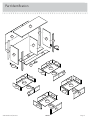
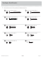
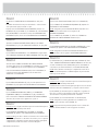
å While not all parts are labeled, some of the parts will have a label or an inked letter on the ede
to help distinuish similar parts from each other. Use this part identifi cation to help identify similar parts.
Part Identifi cation
A RIGHT END (1)
B LEFT END (1)
C UPRIGHT (1)
D TOP (1)
D10 SMALL RIGHT DRAWER SIDE (2)
D11 SMALL LEFT DRAWER SIDE (2)
D132 RIGHT DRAWER SIDE (4)
D138 LEFT DRAWER SIDE (4)
D166 SMALL DRAWER BACK (2)
D167 DRAWER BACK (4)
D975 DRAWER BOTTOM (6)
E BOTTOM (2)
F BACK (1)
G RIGHT FRONT LEG (1)
H LEFT FRONT LEG (1)
I REAR LEG (2)
K2 SMALL RIGHT DRAWER FRONT (1)
L2 SMALL LEFT DRAWER FRONT (1)
M65 DRAWER BRACE (6)
M72 END MOLDING (2)
Q2 RIGHT DRAWER FRONT (2)
R2 LEFT DRAWER FRONT (2)
SS BRACE (1)

Part Identifi cation
409937www.sauder.com/services
Pae 3
A
B
C
D
E
F
G
H
I
M72
E
M72
I
SS
D10
D11
D132
D138
D166
D167
D975
K2
L2
M65
M65
M65
M65
R2
Q2
D975
D975
D975
D10
D11
D166
D167
D132
D138

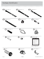
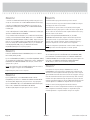
Hardware Identifi cation
409937 www.sauder.com/servicesPae 4
AA2
HIDDEN CAM - 22
CC2
CAM DOWEL - 10
BB2
CAM SCREW -12
40CB
CABINET LEFT - 6
40CA
CABINET RIGHT - 6
40CC
DRAWER RIGHT - 6
40CD
DRAWER LEFT - 6
EE
PULL - 8
KNOB - 4
FF
METAL PIN - 4
GG
SLIDE CAM - 12
HH JJ
WARNING LABEL - 1
(Refer to step 15 for proper
location and application)
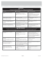
WARNING
Serious or fatal crushing injuries can occur
from furniture tip-over. To help prevent
tip-over:
• Place heaviest items in the lowest drawers.
• Unless specifi cally desined to accommodate, do not
set TVs or other heavy objects on top of this product.
• Never allow children to climb or han on drawers,
doors, or shelves.
• Never open more than one drawer at a time.
• If equipped with a drawer interlock system, do not
defeat or remove it.
Use of tip-over restraints may only reduce, but not
eliminate, the risk of tip-over.
This is a permanent label. Do not attempt to remove!
04/10 332296
FOOT - 1
TT
FOOT BASE - 1
UU WW
SAFETY BRACKET - 1

Hardware Identifi cation
å Screws are shown actual size. You may receive extra hardware with your unit.
409937www.sauder.com/services
Pae 5
BLACK 1-1/8" MACHINE SCREW - 4
MM
SILVER 3/4" MACHINE SCREW - 16
NN
BLACK 9/16" LARGE HEAD SCREW - 1
XX
BLACK 1-1/4" FLAT HEAD SCREW - 4
VV
BLACK 1-7/8" FLAT HEAD SCREW - 3
LL
GOLD 5/16" FLAT HEAD SCREW - 48
QQ
NAIL - 47
RR
BLACK 9/16" FLAT HEAD SCREW - 4
OO
BLACK 2-1/4" FLAT HEAD SCREW - 6
KK
30S
BLACK 1-9/16" FLAT HEAD SCREW - 30

Step 1
Look for this icon. It means a
video assembly tip is available at
www.sauder.com/services/tips
å
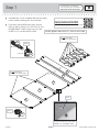
Assemble your unit on a carpeted fl oor or on the empty
carton to avoid scratchin your unit or the fl oor.
å
Push twenty-two HIDDEN CAMS (AA2) into the
ENDS (A and B), UPRIGHT (C), BOTTOMS (E), and
DRAWER BRACES (M65). Then, insert ten CAM
DOWELS (CC2) into the HIDDEN CAMS.
409937 www.sauder.com/servicesPae 6
A
B
C
E
E
Do not tihten the HIDDEN CAMS in this step.
(22 used)
(10 used)
Arrow
Insert the metal end of the CAM
DOWEL into the HIDDEN CAM.
Arrow
Do not insert CAM
DOWELS into these edes.
Do not insert CAM
DOWELS into these parts.
AA2
CC2
Arrow
AA2
Scan this QR code or go to this address:
http://qr.sauder.com/?ID=1444
to watch a video on how to assemble your unit.
M65
M65
M65
M65
M65
M65

Step 2
å
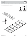
Turn twelve CAM SCREWS (BB2) into the FRONT LEGS (G
and H) and DRAWER FRONTS (K2, L2, Q2, and R2).
409937www.sauder.com/services
Pae 7
G
H
K2
L2
Q2
Q2
R2
R2
BB2
(12 used)

å
Fasten the REAR LEGS (I) to the ENDS (A and B). Use six
BLACK 2-1/4" FLAT HEAD SCREWS (KK).
Step 3
409937 www.sauder.com/servicesPae 8
A
I
B
I
Surface without
HIDDEN CAMS
Surface without
HIDDEN CAMS
Flat ede
BLACK 2-1/4" FLAT HEAD SCREW
(6 used in this step)
KK

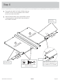
Step 4
409937www.sauder.com/services
Pae 9
A
B
M72
M72
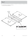
å
Turn four BLACK 9/16" FLAT HEAD SCREWS (OO) into
the ENDS (A and B) until the shoulders of the SCREWS
rest on the surfaces of the ENDS.
å
Slide the END MOLDINGS (M72) onto the ENDS (A and B).
Line up the rooves in the MOLDINGS over the heads of
the SCREWS in the ENDS.
These edes
should be even.
These edes
should be even.
Shoulder
BLACK 9/16" FLAT HEAD SCREW
(4 used in this step)
OO
Surface without
HIDDEN CAMS
Surface without
HIDDEN CAMS
Apply pressure with your hands
as you uide the MOLDINGS over
the SCREWS and onto the ENDS.

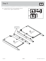
Step 5
409937 www.sauder.com/servicesPae 10
A
G
B
H
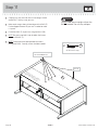
å
Fasten the FRONT LEGS (G and H) to the other surface of
the ENDS (A and B). Tihten six HIDDEN CAMS.
1
2
Anled ede
Surface with
HIDDEN CAMS
Surface with
HIDDEN CAMS

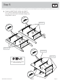
å
Fasten the CABINET RIGHTS (40CA) and CABINET
LEFTS (40CB) to the ENDS (A and B) and UPRIGHT(C).
Use twenty-four GOLD 5/16" FLAT HEAD SCREWS (QQ)
throuh holes #1 and #4.
Step 6
409937www.sauder.com/services
Pae 11
C
A
G
B
H
GOLD 5/16" FLAT HEAD SCREW
(24 used in this step)
QQ
1
2
3
4
1
2
3
4
1
2
3
4
1
2
3
4
Roller end
Surface with
HIDDEN CAMS
Surface with
HIDDEN CAMS
1
2
4
1
2
4
Roller end
Finished ede
Surface with
HIDDEN CAMS
1
2
3
4
1
2
3
4
1
2
3
4
Roller end
1
2
3
4
3
4
3
4
3
3
3
3

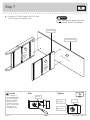
å
Fasten the LEFT END (B) and UPRIGHT (C) to the
TOP (D). Tihten four HIDDEN CAMS.
Step 7
409937 www.sauder.com/servicesPae 12
Start Tighten
Arrow
Minimum
190 derees
Caution
Risk of damae or
injury. HIDDEN CAMS
must be completely
tihtened. HIDDEN
CAMS that are not
completely tihtened
may loosen, and parts
may separate. To
completely tihten:
Arrow
Maximum
210 derees
B
C
D
H
Unfi nished surface
Finished ede
Lon fi nished ede
Surface
with
HIDDEN
CAMS
Surface
without
HIDDEN
CAMS
Do not stand the unit upriht without the
BACK fastened. The unit may collapse.
Caution

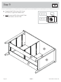
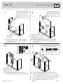
å
Insert four METAL PINS (GG) into the BOTTOMS (E).
å
Fasten the BOTTOMS (E) to the LEFT END (B). Tihten
two HIDDEN CAMS.
å
NOTE: Be sure the METAL PINS in the BOTTOMS insert
into the holes in the LEFT END.
å
Fasten the BOTTOMS (E) to the UPRIGHT (C). Use two
BLACK 1-7/8" FLAT HEAD SCREWS (LL).
Step 8
409937www.sauder.com/services
Pae 13
B
C
E
E
GG
Surface with
HIDDEN CAMS
Surface with
HIDDEN CAMS
Arrow
Minimum
190 derees
Maximum
210 derees
Finished ede
BLACK 1-7/8" FLAT HEAD SCREW
(2 used in this step)
LL
Finished ede
(4 used)

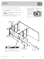
å
Fasten the RIGHT END (A) to the TOP (D) and
BOTTOMS (E). Tihten four HIDDEN CAMS.
å
NOTE: Be sure the METAL PINS in the BOTTOMS
insert into the holes in the RIGHT END.
Step 9
409937 www.sauder.com/servicesPae 14
Arrow
Minimum
190 derees
Maximum
210 derees
E
E
D
A
G

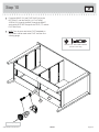
å
Fasten the BRACE (SS) and FOOT BASE (UU) to the
BOTTOM (E). Use four BLACK 1-1/4" FLAT HEAD
SCREWS (VV) throuh the BASE, throuh the BRACE,
and into the BOTTOM. Then, push the FOOT (TT) into the
FOOT BASE (UU).
å
NOTE: Turn the screw end of the FOOT completely in.
Adjustments will be made to the FOOT after the unit is
standin upriht.
Step 10
409937www.sauder.com/services
Pae 15
E
TT
UU
SS
BLACK 1-1/4" FLAT HEAD SCREW
(4 used in this step)
VV
Turn completely in.

Step 11
409937 www.sauder.com/servicesPae 16
å
Carefully turn your unit over onto its front edes. Unfold
the BACK (F) and lay it over your unit.
å
Make equal marins alon all four edes of the BACK (F).
Push on opposite corners of your unit if needed to make
it “square”.
å
Fasten the BACK (F) to your unit usin the NAILS (RR).
å
NOTE: Be sure to tap NAILS into the holes that line up
over the UPRIGHT (C).
å
NOTE: Perforations have been provided for access
throuh the BACK. Carefully cut out the holes needed.
NAIL
(47 used in this step)
RR
F
Printed information
must be facin up.
These holes must line up
over the UPRIGHT (C).
Cut-out
Do not stand the unit upriht without the
BACK fastened. The unit may collapse.
Caution

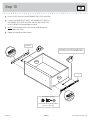
Step 12
409937www.sauder.com/services
Pae 17
VIEW THE T-LOCK BOX VIDEO
å
Insert the DRAWER SIDES (D132 and D138) at
an angle into the slot at each end of the RIGHT
DRAWER FRONT (Q2).
å
Slide the DRAWER BOTTOM (D975) into the grooves
in the DRAWER SIDES (D132 and D138) and RIGHT
DRAWER FRONT (Q2).
å
Fasten the DRAWER BRACE (M65) to the
DRAWER FRONT (Q2). Tighten one HIDDEN CAM.
å
Fasten the DRAWER BACK (D167) to the DRAWER SIDES (D132
and D138) and DRAWER BRACE (M65). Use five BLACK 1-9/16"
FLAT HEAD SCREWS (30S). Repeat this step for the other DRAWERS
using the DRAWER FRONTS (Q2 and R2). Use the SMALL DRAWER
FRONTS (K2 and L2), SMALL DRAWER SIDES (D10 and D11), and
SMALL DRAWER BACKS (D166) for the small drawers.
12
34
Be sure the DRAWER
BOTTOM inserts into the
DRAWER FRONT roove.
Groove
Q2
Q2
D138
D975
D132
D132
D138
D167
Q2
D138
D132
M65
30S
Start each screw a few turns before
completely tihtenin any of them.
BLACK 1-9/16" FLAT HEAD SCREW
(30 used in this step)
1
2
Unfi nished
surface
The tabs should insert freely
into the slots. Gently tilt the
DRAWER SIDES side to side
until the tabs slip into the slots.
With the palm of your hand,
tap the DRAWER BOTTOM
down into the roove.
M65
Surface with
HIDDEN CAM

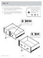
Step 13
409937 www.sauder.com/servicesPae 18
å
Insert a SLIDE CAM (HH) into the DRAWER SIDES (D132 and D138).
å
Fasten the DRAWER RIGHT (40CC) and DRAWER LEFT (40CD) to
the DRAWER SIDES (D132 and D138). Use four GOLD 5/16" FLAT
HEAD SCREWS (QQ) throuh holes #1 and #4.
å
NOTE: The screw head in the CAM must be visible throuh the
slotted hole in the SLIDE.
å
Repeat this step for the other drawers.
1
2
3
4
Roller end
Roller end
Screw head - turn CAM to line up holes in
the SLIDES with holes in DRAWER SIDES
HH
HH
1
2
3
4
D138
D132
GOLD 5/16" FLAT HEAD SCREW
(24 used in this step)
QQ
(4 screws per drawer)

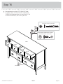
å
Fasten the KNOBS (FF) to the SMALL RIGHT DRAWER
FRONT (K2). Use two BLACK 1-1/8" MACHINE SCREWS (MM).
Repeat this step for the other small drawer.
å
Fasten the PULLS (EE) to the RIGHT DRAWER FRONT (Q2).
Use four SILVER 3/4" MACHINE SCREWS (NN). Repeat this
step for the other drawers.
Step 14
409937www.sauder.com/services
Pae 19
EE
FF
Q2
K2
SILVER 3/4" MACHINE SCREW
(16 used for the PULLS)
NN
BLACK 1-1/8" MACHINE SCREW
(4 used for the KNOBS)
MM
Want options? Customize
your item with add-on
hardware kits available
on sauder.com.

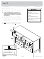
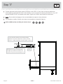
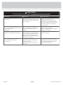
å
Carefully stand your unit upriht.
å
Position your unit in its fi nal location. Turn the FOOT down
so it touches the fl oor.
å
To insert the drawers into your unit, tip the front of the
drawer down and drop the rollers on the drawer behind
the rollers on the unit. Lift the front of the drawer up and
slide it into the unit.
å
Apply the WARNING LABEL (JJ) to the upper LEFT
DRAWER SIDE (D11). You should be able to read the label
when the drawer is open. When the drawer is closed, it will
hide the label. Peel o the backin and apply the label as
shown in the diaram.
å
NOTE: This is a permanent label intended to last for the
life of the product. Once applied, do not try to remove it.
Step 15
409937 www.sauder.com/servicesPae 20
Q2
Q2
R2
K2
L2
R2
Serious or fatal crushin injuries can
occur from furniture tip-over. To help
prevent tip-over:
-Place heaviest items in the lowest drawers.
-Unless specifi cally desined to accommodate,
do not set TVs or other heavy objects on top of
this product.
-Never allow children to climb or han on
drawers, doors, or shelves.
-Never open more than one drawer at a time.
-If equipped with a drawer interlock system, do not
defeat or remove it.
Use of tip-over restraints may only reduce,
but not eliminate, the risk of tip-over.
WARNING
D11
Turn the ADJUSTABLE FOOT
downward until it touches the fl oor.
TT
Floor
IMPORTANT: The ADJUSTABLE FOOT should not
extend beyond the bottom edes of the LEGS.
JJ
La page est en cours de chargement...
La page est en cours de chargement...
La page est en cours de chargement...
La page est en cours de chargement...
La page est en cours de chargement...
La page est en cours de chargement...
La page est en cours de chargement...
La page est en cours de chargement...
La page est en cours de chargement...
La page est en cours de chargement...
La page est en cours de chargement...
La page est en cours de chargement...
-
 1
1
-
 2
2
-
 3
3
-
 4
4
-
 5
5
-
 6
6
-
 7
7
-
 8
8
-
 9
9
-
 10
10
-
 11
11
-
 12
12
-
 13
13
-
 14
14
-
 15
15
-
 16
16
-
 17
17
-
 18
18
-
 19
19
-
 20
20
-
 21
21
-
 22
22
-
 23
23
-
 24
24
-
 25
25
-
 26
26
-
 27
27
-
 28
28
-
 29
29
-
 30
30
-
 31
31
-
 32
32


Sauder Shoal Creek 410287 Mode d'emploi
- Taper
- Mode d'emploi
- Ce manuel convient également à
dans d''autres langues
Documents connexes
-
Sauder 409937 Assembly Instructions Manual
-
-
-
-
-
-
-
-
-