Elkron DT600 Guide d'installation
- Catégorie
- Éclairage de confort
- Taper
- Guide d'installation

DS80IM41-001C
DT600
Rivelatore radio a doppia tecnologia
da esterno a effetto tenda
Dual technology radio detector for
exterior use with curtain effect
Funk-Außendetektor mit doppelter
Technologie und Vorhangeffekt
Détecteur radio à double
technologie pour l'extérieur en
rideau
Manuale d’uso, installazione e programmazione
Installation programming and functions manual
Installations
-, programmier- und gebrauchsanleitun
Notice di installation, programmation et utilization
I EN DE FR

2 DS80IM41-001C
ITALIANO
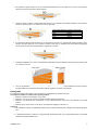
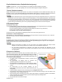
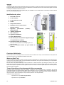
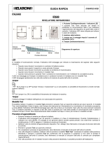
Il DT600 è un rivelatore a doppia tecnologia da esterno a effetto tenda, con sensore di movimento passivo a infrarossi (PIR) e
micro onda, in grado di rilevare i movimenti in un'area assegnata e trasmetterlo all’unità di controllo per attivare l'allarme
intrusione.
La base del prodotto presenta delle predisposizioni per i fori che consentono l'installazione su una superficie piana, utilizzando,
nel caso fosse necessario, la staffa a 90° o uno snodo (opzionali).
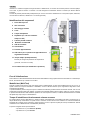
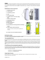
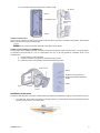
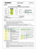
Identificazione dei componenti
1. Filtro LED copri vite
2. Vite di chiusura
3. Vite fissaggio scheda
4. Lente
5. Tamper antiapertura
6. Dip Switch (4 e 5 da non utilizzare:
sempre in OFF)
7. Trimmer portata rivelatore
8. Elemento sensibile PIR
9. LED del rivelatore
10. Vano batteria
11. Pulsante Apprendimento
12. LED interno per le operazioni di apprendimento e
segnalazione batteria
13. Jumper tamper (antiasportazione)
Previsto per collegare la protezione anti asportazione
(opzionale, non fornito a corredo)
14. Per utilizzi futuri (non modificare la posizione)
Fase di inizializzazione
Tale condizione si attiva automaticamente all’inserimento della batteria e ad ogni apertura/chiusura del frontalino. Si manterrà per
60 sec, durante tale tempo il rivelatore non è attivo.
Modalità test (Walk Test)
Aprendo il frontalino del sensore, dopo aver atteso la fase di inizializzazione, si entra nella modalità di test per circa 4 min. In
questa condizione il tempo di interdizione è disabilitato, mentre il LED del rivelatore per la segnalazione degli allarmi viene
automaticamente abilitato.
In questa modalità si possono eseguire le prove di rilevazione verificando gli allarmi tramite l’accensione del LED, così come la
portata della connessione radio (per i dettagli, consultare il manuale della relativa unità di controllo). Trascorsi i 4 minuti, il sensore
si porterà automaticamente nella condizione operativa. Se viene riaperto il frontalino, si riattiverà automaticamente la modalità
test (Walk Test), dopo il tempo di inizializzazione.
Tempo di interdizione e funzionamento a basso consumo
Per evitare elevati consumi della batteria, il rivelatore inibisce automaticamente la segnalazione di allarmi consecutivi per un
tempo definito tempo di interdizione. In questo modo, il movimento continuo di fronte a un rivelatore non scaricherà inutilmente
la batteria. Ne consegue che tra un allarme e quello successivo occorre un periodo di quiete pari al tempo d’interdizione. Questa
caratteristica non è abilitata durante la modalità test ( Walk Test).
Si possono scegliere due tempi di interdizione:
- Dip Switch N° 2 in pos. OFF 4 min (Default)
- Dip Switch N° 2 in pos. ON 8 min
1
2
4

DS80IM41-001C 3
Funzione Supervisione
Quando il rivelatore è in modalità di funzionamento normale, effettua periodicamente un test di autodiagnostica, trasmettendo
un segnale di supervisione randomico ogni 30 - 50 minuti.
Funzione Sensibilità (Aumento di sensibilità)
NORMAL: Dip Switch N°1 in pos. OFF (Default). Indicata per la maggior parte delle installazioni da esterno.
HIGH: Dip Switch N°1 in pos. ON. Indicata qualora sia richiesta una velocità di rilevazione maggiore.
Trimmer (portata sensore)
Regola la portata del sensore (ruotando il trimmer in senso orario si aumenta la portata del rivelatore). Per la regolazione tenere
a riferimento il campo di azione determinato dalla micro onda. Il sensore adeguerà automaticamente il funzionamento
dell'infrarosso a questa regolazione. Di default la posizione del trimmer è ruotata completamente in senso orario.
<NOTA>
Al contrario della microonda, per la quale è possibile stabilire con sufficiente precisione il suo limite di rilevazione, per
l'infrarosso questa condizione non è applicabile. Questo perché la rilevazione dell'infrarosso è condizionata dalla temperatura
ambientale, dall'abbigliamento dell'intruso, dalla assenza/presenza di vento etc. Il trimmer quindi regola automaticamente la
capacità di rilevazione dell'Infrarosso in funzione della portata della microonda selezionata senza necessariamente delimitarne
il suo campo di azione a quello della microonda stessa (l'infrarosso sarà configurato per le condizioni più sfavorevoli a quella
portata).
Indicatore LED rivelatore
Dip Switch N° 3 in pos. OFF
In modalità di funzionamento normale, l'indicatore LED lampeggia per indicare la trasmissione del segnale nelle seguenti
situazioni:
Quando viene alimentato, lampeggia per 60 secondi (fase di inizializzazione).
Quando viene aperto il coperchio e viene azionato l'interruttore tamper, per 4 minuti (modalità test).
Durante la modalità test a ogni movimento rilevato
Se il tamper è aperto, a ogni movimento rilevato
Non lampeggia se viene rilevato un movimento in modalità normale e con tamper chiuso.
Dip Switch N°3 in posizione ON (Default)
Il Led lampeggia anche quando viene rilevato un movimento in modalità funzionamento normale e con tamper chiuso, a scapito
della durata della batteria. Inibito appena inizia il tempo di interdizione.
Batteria
Il rivelatore è alimentato da una batteria al litio CR2 3V, in dotazione all’interno dell’imballo. Il rivelatore è in grado di rilevare lo
stato di batteria scarica, inviando un segnale all’unità di controllo insieme alle normali trasmissioni di segnali affinché la centrale
visualizzi lo stato corrispondente.
<NOTA>
Durante la sostituzione della batteria, dopo aver rimosso la batteria esausta, premere il tamper due volte per
scaricare completamente il dispositivo prima di inserire la batteria nuova.
Per verificare il funzionamento corretto, eseguire un Walk Test di portata e livello di segnale radio premendo il tasto
di apprendimento, tasto 11 (fare riferimento al manuale di istruzioni della unità di controllo).
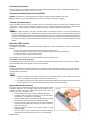
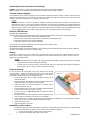
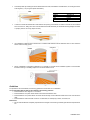
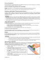
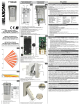
Apprendimento del rivelatore
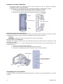
Per aprire il sensore, sollevare il filtro LED coprivite e svitare la vite di chiusura
sottostante. Allentare la vite di fissaggio scheda senza svitarla del tutto e
smontare la scheda elettronica, sollevandola dapprima verso l’alto per
sganciarla dalla vite, come illustrato a lato.
Inserire la batteria CR2 nel vano batteria, rispettando la polarità.
L'indicatore LED del rivelatore lampeggerà per 60 secondi (fase di
inizializzazione). Il rivelatore non è ancora attivo.
Abilitare l’unità di controllo all’apprendimento dispositivi. Per i dettagli,
fare riferimento al manuale di istruzione dell’unità di controllo.
Premere il pulsante di apprendimento sul circuito radio e completare il
processo di apprendimento (fare riferimento al manuale di istruzioni
della unità di controllo).
Una volta appreso il rivelatore, porre l’unità di controllo in “Test
dispositivi radio”
Inserire il circuito sul fondo, avvitare la vite e richiudere il frontalino,
posizionando il rivelatore nella posizione in cui lo si vuole installare.

4 DS80IM41-001C
Verificata la copertura radio si potrà riaprire il frontalino, smontare il circuito e fissare il rivelatore direttamente alla parete
o attraverso la staffa e snodo opzionali
Serrare la vite di chiusura.
Applicare il filtro Led copri vite.
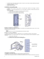
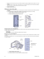
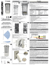
Installazione su superficie piana
Il rivelatore è stato concepito per essere montato su una superficie piana, mediante le viti di fissaggio e i tasselli in
dotazione.
Sulla base sono presenti delle predisposizioni per i fori, dove la plastica è più sottile e può essere forata allo scopo di
effettuare il montaggio.
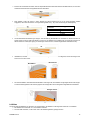
I. Incidere la sede A e la sede B sul fondo (vedere immagine successiva).
II. Usando la dima dei fori, praticare i fori sulla superficie
III. Fissare il fondo con le apposite viti tramite le sedi A e B.
Montaggio con staffa a 90° (cod. 80SP4D00113)
Fiissare prima la staffa 90° alla parete con le apposite viti e poi fissare il fondo alla staffa tramite le sedi A e B con le viti di
fissaggio. Riavvitare la scheda al fondo.
<
<N
NO
OT
TA
A>
>
La staffa a 90° può essere montata indifferentemente verso destra o sinistra
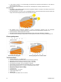
Montaggio con snodo cod. 80SP5D00113
Lo snodo può essere applicato in orizzontale, o direttamente al muro con le apposite viti e tasselli, o tramite il supporto.
Permette orientamenti di +/- 45° sul piano verticale e +30°, nel verso contrario a quello delle “Frecce di Orientamento”, sul piano
orizzontale.
I. Forare le sedi C e D sul fondo
II. Orientare lo snodo e serrare la vite di bloccaggio snodo.
III. Posizionare il fondo sullo snodo con le viti di fissaggio staffa.
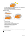
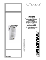
Consigli per l'installazione
L’installazione deve essere effettuata in luoghi protetti da agenti atmosferici.
Il rivelatore è stato concepito per funzionare con una portata di rilevamento di 8 metri, e montato ad un'altezza di 2 metri da terra.
Foro a sfondare per
l’accesso alla vite di
regolazione snodo

DS80IM41-001C 5
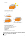
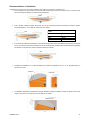
Per protezioni di pareti, evitare che una zona sensibile dell'Infrarosso si trovi a contatto con il muro per non annullare il
beneficio del sensore infrarosso a doppio elemento.
Ovviare a questo montando il sensore distaccato dal muro, come illustrato nella tabella sottostante, od orientando il
sensore di qualche grado (< 10°) utilizzando lo snodo opzionale):
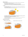
Per aumentare l’efficacia della rilevazione si può aumentare anche oltre i 10° l’apertura del rivelatore rispetto al muro,
facendo comunque attenzione a non puntare il rivelatore verso aree con probabili cause di falsi allarmi (passaggi di
mezzi o persone, presenza di oggetti instabili o vegetazione a chioma).
Prediligere installazioni ove ci sia un muro/pavimento a delimitare il campo di rilevazione del sensore. Non puntare quindi
mai il sensore nel vuoto:
Ove non sia possibile una installazione Parete/Parete o Soffitto/Pavimento prediligere l'istallazione a sensore inclinato.
Escludere dalla zona di rilevazione del sensore qualsiasi oggetto in movimento od oscillante.
Linee guida
Per ottimizzare l'impiego del rivelatore, occorre prendere in considerazione le seguenti linee guida.
Si consiglia di installare il rivelatore nelle seguenti posizioni:
Montare il rilevatore ad un'altezza di 1,9-2,0 metri
Montare in un luogo ove gli animali non possano accedere all'area di rilevamento.
Montare in una posizione dove normalmente un intruso attraverserebbe il campo visivo del rivelatore da una parte
all'altra.
Montare dove il campo visivo non sia ostruito, per esempio da tendaggi, ornamenti, ecc.
Limitazioni
Non installare il rivelatore completamente esposto alla luce del sole diretta. Evitare di dirigerlo verso vetrate esposte al
sole.
In installazioni da esterno, evitare che i raggi del SOLE, specialmente nelle ore più calde della giornata, arrivino diretti
all'elemento sensibile dell'Infrarosso.
Tabella della distanza A
in funzione della portata
Portata
Distanza A
8 mt 70 cm
4 mt 35 cm
2 mt 18 cm

6 DS80IM41-001C
Non installare il rivelatore in aree ove sono presenti dispositivi che possono provocare cambiamenti repentini di
temperatura nell'area di rilevamento, ovvero condizionatori d'aria, termosifoni, ecc.
Evitare gli ostacoli di grandi dimensioni nell'area di rilevamento.
Non puntare direttamente verso sorgenti di calore, come fuochi o caldaie, e non installare sopra radiatori.
Evitare che vi siano oggetti in movimento nell'area di rilevamento, ovvero tende, tappezzerie, ecc.
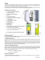
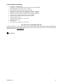
Diagrammi di rilevazione
Specifiche tecniche
Alimentazione: 1 batteria CR2 3V
Autonomia: 2 anni (valore tipico, può variare in base all’uso)
Banda di frequenza Microonda: 24,12 – 24,13 Ghz
Banda di frequenza bidirezionale: 868,6 – 868,7 MHz
Assorbimento di corrente in stand by (operativa): 15uA (solo rivelatore) + modulo TX
Assorbimento di corrente in allarme con LED accesso: 3,5 mA + modulo TX
Portata microonda: minima 2m / massima 8m con regolazione da trimmer
Potenza radio Microonda massima trasmessa: 18,68 dBm
Potenza radio bidirezionale massima trasmessa: 1,81 dBm
Livello di protezione: IP54
Temperatura lavoro: - 10°C/+55°C
Umidita Ambientale: 95%
Peso: 300g
Dimensioni senza accessori 110 x 42 x 62 mm
DICHIARAZIONE DI CONFORMITÀ UE SEMPLIFICATA
Il fabbricante, URMET S.p.A., dichiara che il tipo di apparecchiatura radio: RIVELATORE DOPPIA TECNOLOGIA DA ESTERNO
EFFETTO TENDA DT600 è conforme alla direttiva 2014/53/UE. Il testo completo della dichiarazione di conformità UE è disponibile
al seguente indirizzo Internet: www.elkron.com
FR / UK / RUS
Diagramma di rilevazione standard Diagramma di rilevazione alla massima altezza

DS80IM41-001C 7
ENGLISH
The DT600 is a dual technology detector for exterior use with a curtain effect and passive infra-red (PIR) and microwave motion
sensor capable of detecting movements in an assigned area and indicate them to the control panel to activate the intrusion alarm.
The base of the product has holes to allow installation on a flat surface, using - if necessary - the 90° bracket and an articulation
(optional).
Identification of the components
1. LED filter screw covers
2. Closure screws
3. Card-fastening screws
4. Lens
5. Anti-opening tamper
6. Dip Switch (never use 4 and 5: always
OFF)
7. Detector capacity trimmer
8. PIR sensitive element
9. Detector LED
10. Battery compartment
11. Learning Button
12. Internal LED for the learning operations and battery
signals
13. Jumper tamper (removal protection)
Intended to connect the removal protection (optional, not
included)
14. For future uses (do not modify the position)
Initialisation phase
This condition is activated automatically when the battery is enabled and at each opening/closure of the front panel. It will remain
in this mode for 60 seconds, during which the detector is not active.
Test mode (Walk Test)
By opening the front panel of the sensor, after having waited for the initialisation phase to finish, the Test Mode is launched and
lasts about 4 minutes. In this condition the cut-off time is disabled, while the LED of the detector of the alarm signal is automatically
enabled.
When in this mode, the detection tests can be conducted to verify the alarms by turning on the LED and the radio connection
capacity can be tested (for details, consult the manual for the control unit). After 4 minutes, the sensor will automatically revert to
operating condition. If the front panel is reopened, the test mode (Walk Test) will be automatically reactivated, after the initialisation
time.
Cut-off time and low-consumption operation
To avoid high consumption of the battery, the detector automatically inhibits consecutive alarm signals for a set cut-off time. In
this way, the continuous movement in front o fa detector will not deplete the battery uselessly. Then between one alarm and the
next one there will be a period of silence equal to the cut-off time. This feature is not enabled during the test mode (Walk Test).
There is a choice of two cut-off times:
- Dip Switch N° 2 in OFF position 4 min (Default)
- Dip Switch N° 2 in ON position 8 min
Supervision Function
When the detector is in normal functioning mode, it periodically conducts a self-diagnostic test, transmitting a random
supervision signal every 30-50 minutes.
1
2
4

8 DS80IM41-001C
Sensitivity Function (Increase of Sensitivity)
NORMAL: Dip Switch N°1 in OFF position (Default). Recommended for most exterior installations.
HIGH: Dip Switch N°1 in ON position. Recommended when a higher detection speed is required.
Trimmer (sensor capacity)
This regulates the sensor capacity (turning the trimmer clockwise increases the detector capacity). To adjust it, keep in mind the
operating area determined by the microwave. The sensor will automatically adapt the functioning of the infra-red with this
regulation. The trimmer default position is completely clockwise turned.
<NOTE>
Unlike the microwave, for which it is possible to establish its detector limit with sufficient precision, this condition is not
applicable for the infra-red. The reason is because the detection of the infra-red is conditioned by the ambient temperature,
by the intruder’s clothing, by the absence/presence of wind, etc. The trimmer therefore automatically regulates the infra-red
detection capacity in function of the capacity of the microwave selected without necessarily defining its operating area as that
of the microwave itself (the infra-red will be configured for the most unfavourable conditions at that capacity).
Detector LED indicator
Dip Switch N° 3 in OFF position
In the normal operating mode, the LED indicator blinks to indicate the transmission of the signal in the following situations:
When it is powered, it blinks for 60 seconds (initialisation phase).
When the cover is open and the tamper switch is activated, for 4 minutes (test mode).
During the test mode for every movement detected
If the tamper is open, for every movement detected.
It does not blink if a movement is detected in normal mode and with the tamper closed.
Dip Switch N°3 in ON position (Default)
The LED also blinks when a movement is detected in normal operating mode and with the tamper closed, at the cost of depleting
the battery. It is inhibited as soon as the cut-off time starts.
Battery
The detector is powered by a CR2 3V lithium battery provided in the package. The detector is capable of detecting the flat
battery status, sending a signal to the control unit together with the normal transmission of signals so that the control unit
displays the corresponding status.
<NOTE>
During the replacement of the battery, after having removed the dead battery, press the tamper twice to completely
discharge the device before inserting the new battery.
To check that it is functioning correctly, conduct the Walk Test for the radio signal level capacity by pressing the
learning button, button 11 (see the control unit instruction manual).
Detector learning
To open the sensor, lift the LED filter screw covers and loosen the closure
screws beneath it. Loosen the screws that hold the card in place without
unscrewing them completely and disassemble the electronic card, lifting it
upward first to release it from the screw, as illustrated here.
Insert the CR2 battery into the battery compartment, taking care to
observe the polarity.
When the detector LED indicator is powered, it blinks for 60 seconds
(initialisation phase). The detector is not yet activated.
Enable the control unit for the learning device. For details, see the
control unit instruction manual.
Press the learning button on the radio circuit and complete the learning
process (see the control unit instruction manual).
Put the control unit in “Radio Device Test” mode after the detector
learning procedure.
Insert the circuit on the bottom, tighten the screws and close the front
panel, positioning the detector in the where it is to be installed.
Once the radio cover is checked, it is possible to reopen the front panel, disassemble the circuit and attach the detector
directly onto the wall or using the bracket and optional articulation.
Tighten the closure screws.
Apply the LED filter screw covers.
Installation on flat surfaces
The detector was designed to be assembled on a flat surface, using the fastening screws and the anchor bolts provided.
The base is marked where the plastic is thinner for boring holes suitable for installation.
I. Cut seat A and seat B on the bottom (see the image below).
II. Using the holes template, make holes on the surface.
Card screw

DS80IM41-001C 9
III. Fix the bottom using the special screws in seats A and B.
Installation with the 90° bracket (ref. 80SP4D00113)
First fix the 90° bracket to the wall with the special screws and then fix the base to the bracket using seats A and B with the
fastening screws. Re-screw the card to the base.
<
<N
NO
OT
TE
E>
>
The 90° bracket can be assembled either to the right or left as desired.
Installation with articulation (ref. 80SP5D00113)
The articulation can be applied horizontally, or directly to the wall with the special screws and anchor bolts, or using the support.
It is possible to orient the base at +/- 45° on a vertical plane and +30°, on the side opposite the “Orientation Arrow”, on the
horizontal plane.
I. Puncture seats C and D on the base.
II. Orient the articulation and tighten the articulation blocking screws.
III. Position the base on the articulation with the bracket fastening screws.
Installation precautions
The detector was designed to work within a detection field of 8 metres and is installed at a height of 2 metres above the ground.
To protect walls, ensure that a zone sensitive to the infra-red is not in contact with the wall so that the benefit of the two-
element infra-red sensor is not compromised.
Seat A
Seat B
Card fastening screw
90° bracket
Wall fastening
screws
Seat C
Seat D
Orientation arrows
Articulation
Support
Centering
elements
Puncture to the very bottom to
access the articulation adjustment
screws.

10 DS80IM41-001C
Avoid this problem by installing the sensor detached from the wall, as illustrated in the table below, or orienting the sensor
a few degrees (< 10°) using the optional articulation):
In order to increase the effectiveness of the detection the opening of the detector in relation to the wall can be increased
even more than 10°, taking care not to orient the detector towards areas likely to cause false alarms (passage of vehicles
or people, presence of moving objects or trees).
It is preferable to install the device where there is a wall/floor that defines the sensor detection area. So never orient the
sensor toward an empty space:
Where a Wall/Wall or Ceiling/Floor installation is not possible, an inclined sensor installation system is recommended.
Exclude all moving or oscillating objects from the sensor detection zone.
Guidelines
To optimise the use of the detector, the following guidelines must be taken into consideration.
It is recommended that the detector be installed in the following positions:
Install the detector at a height of 1.9-2.0 metres.
Install the detector in a place where animals cannot enter the detection area.
Install the detector in a position where an intruder would normally cross the detector's field of vision from one side to the
other.
Install the detector where the field of vision is not obstructed, for example by curtains, ornaments, etc.
Restrictions
Do not install the detector completely exposed to direct sunlight. Avoid orienting it towards glass windows exposed to the
sun.
Distance A table in function of the capacity
Range
Distance A
8 m 70 cm
4 m 35 cm
2 m 18 cm
YES
YES
Wall/Wall Ceiling/Floor
Inclined sensor

DS80IM41-001C 11
In exterior installations, do not allow the infra-red sensor to be exposed to direct SUNLIGHT, especially during the hottest
hours of the day.
Do not install the detector in an area where there are devices that can cause sudden changes of temperature in the
detection area, like air conditioners, radiators, etc.
Do not allow large obstacles in the detection area.
Never orient the device directly towards sources of heat like fires or boilers, and do not install over radiators.
Never allow moving objects into the detection area, like curtains, tapestries, etc.
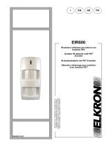
Detection diagrams
Technical specifications
Power supply: 1 battery CR2 3V
Autonomy: 2 years (typical value, can vary according to use)
Microwave radio frequency band: 24,12 – 24,13 GHz
Two-way radio frequency band: 868,6 – 868,7 MHz
Absorption of current in stand-by: 15uA (detector only) + TX module
Absorption of current during alarm with LED on: 3,5 mA + TX module
Microwave capacity: minimum 2 m / maximum 8 m with trimmer regulation
Microwave maximum radio power transmitted: 18,68 dBm
Two-way maximum radio power: 1,81 dBm
Level of protection: IP54
Working temperature: - 10°C/+55°C
Ambient humidity: 95%
Weight: 300g
Dimensions without accessories WxHxD 110 x 42 x 62 mm
SIMPLIFIED CE DECLARATION OF CONFORMITY
The manufacturer, URMET S.p.A., hereby declares that the type of radio device: DUAL TECHNOLOGY DETECTOR FOR
EXTERIOR USE WITH CURTAIN EFFECT DT600 is in conformity with Directive 2014/53/EU. The complete text of the EU
declaration of conformity is available at the following link: www.elkron.com.
FR / UK / RUS
Standard detection diagram Detection at the maximum height diagram
YES
Side view
Side view
Top view

12 DS80IM41-001C
DEUTSCH
Der DT600 ist ein Außendetektor mit doppelter Technologie und Vorhangeffekt. Er ist mit passivem Infrarot-Bewegungssensor
(PIR) kombiniert mit Mikrowellentechnologie ausgestattet und in der Lage, die Bewegung in einem zugeordneten Bereich zu
erfassen und an ein Steuergerät zu übertragen, um den Einbruchalarm auszulösen.
Die Basis des Produkts ist bereits für die Öffnungen ausgelegt, die die Installation auf einer ebenen Oberfläche gestatten. Sollte
dies notwendig sein, können dazu die 90°-Halterung oder ein Gelenk verwendet werden (Optionen).
Identifizierung der Bauteile
1. LED-Filter zur Schraubenabdeckung
2. Verschlussschraube
3. Befestigungsschraube Platine
4. Linse
5. Öffnungsschutz-Tamper
6. Dip-Switch (4 und 5 nicht zu verwenden:
immer auf OFF)
7. Trimmer Detektorreichweite
8. PIR-Fühlglied
9. LED des Detektors
10. Batterieraum
11. Einlern-Taste
12. Innere LED für Einlernvorgänge und Batterieanzeige
13. Jumper-Tamper (Demontageschutz)
Zum Anschluss des Demontageschutzes vorgesehen
(Option, nicht im Lieferumfang enthalten)
14. Für spätere Verwendungen (Position nicht ändern)
Initialisierungsphase
Diese Phase wird beim Einlegen der Batterie und bei jedem Öffnen/Schließen des Frontteils automatisch aktiviert. Sie dauert 60
s und während dieser Zeit ist der Detektor nicht aktiv.
Test-Modus (Walk Test)
Durch Öffnen des Frontteils des Sensors nach dem Ende der Initialisierungsphase beginnt der Test-Modus, der ca. 4 min dauert.
Unter diesen Bedingungen ist die Sperrzeit deaktiviert, während die LED des Detektors für die Alarmmeldung automatisch aktiviert
wird.
In diesem Modus können die Erfassungstests durchgeführt werden, indem die Alarme anhand des Aufleuchtens der LED sowie
die Reichweite der Funkverbindung überprüft werden (wegen Einzelheiten siehe Handbuch des jeweiligen Steuergeräts). Nach
Ablauf der 4 Minuten ist der Sensor automatisch betriebsbereit. Wird das Frontteil erneut geöffnet, wird nach der
Initialisierungszeit automatisch wieder der Test-Modus aktiviert (Walk Test).
Sperrzeit und Energiesparmodus
Um einen hohen Energieverbrauch der Batterie zu vermeiden, sperrt der Detektor die Meldung von aufeinanderfolgenden
Alarmen für einen als Sperrzeit bezeichneten Zeitraum. Auf diese Art und Weise entlädt die kontinuierliche Bewegung vor einem
Detektor die Batterie nicht unnötigerweise. Daraus folgt, dass zwischen einem Alarm und dem nachfolgenden eine Ruhepause
erforderlich ist, die der Sperrzeit entspricht. Diese Eigenschaft ist während des Test-Modus (Walk Test) nicht aktiviert.
Es können zwei Sperrzeiten gewählt werden.
- Dip-Switch Nr. 2 in Pos. OFF 4 min (Standard)
- Dip-Switch Nr. 2 in Pos. ON 8 min
Überwachungsfunktion
Befindet sich der Detektor in der normalen Betriebsart, führt er regelmäßig einen Eigendiagnose-Test durch und überträgt alle
30 - 50 Minuten ein zufälliges Überwachungssignal.
1
2
4

DS80IM41-001C 13
Empfindlichkeitsfunktion (Empfindlichkeitssteigerung)
NORMAL: Dip-Switch Nr. 1 in Pos. OFF (Standard) Für den Großteil der Außeninstallationen angezeigt.
HIGH: Dip-Switch Nr. 1 in Pos. ON. Angezeigt, wenn eine höhere Erfassungsgeschwindigkeit verlangt wird.
Trimmer (Detektorreichweite)
Regelt die Reichweite des Sensors (durch Drehen des Trimmers im Uhrzeigersinn wird die Detektorreichweite erhöht). Zum
Einstellen auf den von der Mikrowelle bestimmten Wirkungsbereich Bezug nehmen. Der Sensor passt die Infrarotfunktion
automatisch dieser Einstellung an. Die Standardposition des Trimmers wird vollständig im Uhrzeigersinn gedreht.
<HINWEIS>
Im Gegensatz zur Mikrowellenfunktion, deren Erfassungsgrenze ausreichend genau festgestellt werden kann, gilt dies für die
Infrarotfunktion nicht. Dies ist dadurch bedingt, dass die Infraroterfassung von der Umgebungstemperatur, der Kleidung des
Eindringlings, den Windverhältnissen, usw. abhängig ist. Der Trimmer regelt daher die Infrarot-Erfassungsleistung abhängig
von der ausgewählten Mikrowellenreichweite, ohne diese dabei notwendigerweise auf den Wirkungsbereich der Mikrowelle
zu beschränken (die Infrarotleistung wird für die ungünstigsten Bedingungen bei dieser Reichweite konfiguriert).
LED-Anzeige Detektor
Dip-Switch Nr. 3 in Pos. OFF
In der normalen Betriebsart blinkt die LED-Anzeige, um die Signalübertragung in den folgenden Situationen anzuzeigen:
Bei Stromversorgung blinkt sie 60 Sekunden (Initialisierungsphase).
Wenn die Abdeckung geöffnet und der Tamper-Schalter betätigt wird 4 Minuten lang (Test-Modus).
Während des Test-Modus bei jeder erfassten Bewegung
Bei geöffnetem Tamper bei jeder erfassten Bewegung
Sie blinkt nicht, wenn im Normalbetrieb eine Bewegung erfasst wird und der Tamper geschlossen ist.
Dip-Switch Nr. in Position ON (Standard)
Die Led blinkt auch, wenn eine Bewegung im Normalbetrieb und bei geschlossenem Tamper erfasst wird, was zu Lasten der
Batteriedauer erfolgt. Unterdrückt, sobald die Sperrzeit beginnt.
Batterie
Der Detektor wird von einer in der Verpackung enthaltenen Lithiumbatterie CR2 3V versorgt. Der Detektor ist in der Lage, die
entladene Batterie zu erkennen und zusammen mit den normalen Signalübertragungen ein Signal an das Steuergerät zu
senden, damit die Zentrale den entsprechenden Status anzeigt.
<HINWEIS>
Während des Ersetzens der Batterie und nach dem Entfernen der entladenen Batterie den Tamper zweimal
betätigen, um die Vorrichtung vollkommen zu entladen, bevor die neue Batterie eingelegt wird.
Um die korrekte Funktionsweise zu überprüfen, einen Walk Test hinsichtlich der Reichweite und des
Funksignalempfangs ausführen, indem die Einlern-Taste betätigt wird, Taste 11 (siehe hierzu Bedienungsanleitung
des Steuergeräts).
Einlernen des Detektors
Zum Öffnen des Sensors den LED-Filter über der Schraube anheben und die
Verschlussschraube darunter lösen. Die Befestigungsschraube der Platine
lösen, ohne sie vollständig abzuschrauben und die Platine entnehmen, indem
diese zuerst nach oben angehoben wird, um sie von der Schraube zu lösen, wie
in der seitlichen Abbildung dargestellt.
Die Batterie CR2 in das Batteriefach einsetzen und dabei auf die
Polarität achten.
Die LED-Anzeige des Detektor blinkt 60 Sekunden lang
(Initialisierungsphase). Der Detektor ist noch nicht aktiv.
Das Steuergerät für das Einlernen von Geräten aktivieren. Wegen
Einzelheiten auf die Bedienungsanleitung des Steuergeräts Bezug
nehmen.
Die Einlern-Taste auf dem Funkkreis betätigen und das
Einlernverfahren abschließen (siehe hierzu Bedienungsanleitung des
Steuergeräts).
Sobald der Detektor eingelernt wurde, das Steuergerät auf "Funkgeräte-Test" stellen.
Den Schaltkreis unten einsetzen, die Schraube anziehen und das Frontteil wieder anbringen. Dann den Detektor in die
Position bringen, in der er installiert werden soll.
Nach Überprüfung des Funkempfangs kann das Frontteil wieder geöffnet, der Schaltkreis ausgebaut und der Detektor
direkt an der Wand oder mit Hilfe der Halterung oder des Gelenks (Optionen) befestigt werden.
Die Verschlussschraube anziehen.
Den Led-Filter über der Schraube anbringen.
Platinenschraube

14 DS80IM41-001C
Installation auf ebener Oberfläche
Der Detektor wurde auf die Montage auf einer ebenen Oberfläche mit den im Lieferumfang enthaltenen
Befestigungsschrauben und Dübeln ausgelegt.
Die Basis ist dort, wo der Kunststoff dünner ist, für die Bohrungen ausgelegt, um die Montage zu gestatten.
I. Den Sitz A und den Sitz B auf dem Boden einschneiden (siehe Bilder im Anschluss).
II. Unter Verwendung der Bohrschablone die Bohrungen an der Oberfläche anbringen.
III. Den Boden mit den dafür vorgesehenen Schrauben über die Sitze A und B befestigen.
Montage mit 90°-Halterung (Cod. 80SP4D00113)
Zuerst die 90°-Halterung mit den dafür vorgesehenen Schrauben an der Wand und dann den Boden über die Sitze A und B mit
den Befestigungsschrauben an der Halterung anbringen. Die Platine wieder am Boden verschrauben.
<
<H
HI
IN
NW
WE
EI
IS
S>
>
Die 90°-Halterung kann sowohl nach rechts als auch nach links montiert werden.
Montage mit Gelenk Cod. 80SP5D00113
Das Gelenk kann waagerecht entweder mit den dafür vorgesehenen Schrauben und Dübeln direkt an der Wand oder mit dem
Halter angebracht werden.
Es gestattet Ausrichtungen von +/- 45° in der senkrechten Ebene und +30° in Gegenrichtung zu den "Ausrichtungspfeilen" in der
waagerechten Ebene.
I. Die Sitze C und D auf dem Boden durchbohren.
II. Das Gelenk ausrichten und die Feststellschraube des Gelenks anziehen.
III. Den Boden mit den Befestigungsschrauben der Halterung auf dem Gelenk positionieren.
Empfehlungen für die Installation
Der Detektor wurde für den Betrieb bei einer Erfassungsreichweite von 8 Metern und auf einer Montagehöhe von 2 Metern
ausgelegt.
Sitze A
Sitze B
Platinenbefestigungsschraub Wandbefestigungsschraube
90°-Halterung
Sitze C
Sitze D
Ausrichtungspfeile
Halter
Gelenk Zentrierer
Öffnung für den Zugang zur
Gelenkeinstellschraube

DS80IM41-001C 15
Zum Schutz von Wänden vermeiden, dass ein empfindlicher Bereich des Infrarotsensors die Wand berührt, um nicht den
Vorteil des Infrarotsensors mit doppeltem Element aufzuheben.
Dem abhelfen, indem der Sensor in einem Abstand zur Wand montiert wird, wie in der unten stehenden Tabelle
angegeben, oder indem der Sensor um einige Grade gedreht wird (< 10°) unter Verwendung der Gelenkoption):
Um die Wirksamkeit der Erfassung zu steigern, kann die Öffnung des Detektors im Verhältnis zur Wand auch über 10°
erhöht werden, wobei in jedem Fall darauf zu achten ist, den Detektor nicht auf Bereiche mit möglichen Ursachen für
falsche Alarme zu richten (Durchgang von Fahrzeugen oder Personen, instabile Gegenstände oder Baumkronen).
Installationen, bei denen eine Mauer/ein Boden den Erfassungsbereich des Sensors begrenzt, sind zu bevorzugen. Den
Sensor nie ins Leere richten:
Wo eine Wand/Wand- oder Decke/Wand-Installation nicht möglich ist, die Installation mit geneigtem Sensor bevorzugen.
Aus dem Erfassungsbereich des Sensors jegliche sich bewegenden oder schwingenden Gegenstände ausschließen.
Leitlinien
Um den Einsatz des Detektors zu optimieren, es wird empfohlen, den Detektor in den folgenden Positionen zu installieren:
Den Detektor auf einer Höhe von 1,9-2,0 Metern montieren.
An einer Stelle montieren, in dem Tiere nicht in den Erfassungsbereich gelangen können.
Tabelle des Abstands A abhängig von der
Reichweite
Reichweite Abstand A
8 m 70 cm
4 m 35 cm
2 m 18 cm
NEIN
JA
JA
Wand/Wand
Mauer/Boden
Geneigter Sensor

16 DS80IM41-001C
In einer Position montieren, in der ein Eindringling normalerweise den Sichtbereich des Detektors von einer Seite zur
anderen überqueren würde.
Dort montieren, wo der Sichtbereich nicht versperrt ist, zum Beispiel durch Vorhänge, Wandschmuck, usw.
Einschränkungen
Den Detektor nicht vollständig direktem Sonnenlicht ausgesetzt installieren. Vermeiden, den Detektor auf der Sonne
ausgesetzte Glasflächen zu richten.
Bei Außeninstallationen vermeiden, dass die SONNENSTRAHLEN, insbesondere während der wärmsten Stunden des
Tages, direkt auf das empfindliche Element des Infrarotsensors treffen.
Den Detektor nicht in Bereichen installieren, in denen Vorrichtungen vorhanden sind, die wiederholte
Temperaturschwankungen im Erfassungsbereich verursachen können bzw. Klimaanlagen, Heizkörper, usw.
Große Hindernisse im Erfassungsbereich vermeiden.
Nicht direkt auf Wärmequellen wie Herde oder Heizkessel richten und nicht über Heizkörpern installieren.
Vermeiden, dass sich bewegliche Gegenstände im Erfassungsbereich befinden wie Vorhänge, Wandbehänge, usw.
Erfassungsdiagramme
Technische Daten
Versorgungsspannung: 1 3 V-Batterie CR2
Autonomie: 2 Jahre (normaler Wert, kann je nach Verwendung schwanken)
Mikrowellen maximale ubertragene funkleistung:: 24,12 – 24,13 Ghz
Bidirektionale maximale ubertragene funkleistung: 868,6 – 868,7 MHz
Stromaufnahme im Standby: 15 uA (nur Detektor) + TX-Modul
Stromaufnahme im Alarmzustand bei eingeschalteter LED: 3,5 mA + TX-Modul
Mikrowellenempfindlichkeit: min. 2 m / max. 8 m bei Einstellung über Trimmer
Mikrowellen fundfrequenz band: 18,68 dBm
Bidirektionale fundfrequenz band: 1,81 dBm
Schutzgrad: IP54
Betriebstemperatur: - 10°C/+55°C
Umgebungsfeuchtigkeit: 95 %
Gewicht: 300g
Abmessungen ohne Zubehör 110 x 42 x 62 mm
Standarderfassungsdiagramm Erfassungsdiagramm auf maximaler Höhe
JA
NEIN
Ansicht von oben
Seitenansicht
Seitenansicht

DS80IM41-001C 17
VEREINFACHTE EU-KONFORMITÄTSERKLÄRUNG
Der Hersteller, URMET S.p.A., erklärt, dass der Funkgerätetyp: AUSSENDETEKTOR MIT DOPPELTER TECHNOLOGIE UND
VORHANGEFFEKT DT600 der Richtlinie 2014/53/UE entspricht. Der ungekürzte Text der EU-Konformitätserklärung steht unter
der folgenden Internetadresse zur Verfügung: www.elkron.com.
FR / UK / RUS

18 DS80IM41-001C
FRANÇAIS
Le détecteur DT600 est équipé de la double technologie pour l'extérieur en rideau avec capteur de mouvement passif aussi bien
à infrarouge (PIR) qu'à micro-ondes, en mesure pour détecter les mouvements dans une zone donnée et les signaler à l'unité de
contrôle pour l’activation de l'alarme d’intrusion.
La base du produit présente des trous prédécoupés pour l'installation sur une surface plate, le cas échéant, à l'aide de l'étrier à
90° ou d'une articulation (en option).
Identification des pièces
1. Filtre LED couvre-vis
2. Vis de fermeture
3. Vis de fixation de la carte
4. Lentille
5. Tamper anti-ouverture
6. Dip Switch (4 et 5 à ne pas utiliser :
toujours sur OFF)
7. Régulateur potentiomètre (Trimmer)
portée détecteur
8. Élément sensible PIR
9. LED du détecteur
10. Logement des batteries
11. Touche Apprentissage
12. LED interne pour les opérations d'apprentissage et
de signalisation de la batterie
13. Interrupteur tamper (anti-sabotage)
Prévu pour relier la protection anti-sabotage (option, non
fournie de série)
14. Pour les utilisations futures (ne pas modifier la
position)
Procédure d'initialisation
Cette condition s'active automatiquement lors de l'introduction de la batterie et à chaque ouverture/fermeture de la façade. Elle
dure 60 secondes au cours desquelles le détecteur reste inactif.
Mode test (Walk Test)
Lors de l'ouverture de la façade du capteur et après la procédure d'initialisation, le dispositif accède en mode de test pendant 4
minutes environ. Dans cette condition, le temps d'interdiction est désactivé, alors que la LED du détecteur pour la signalisation
des alarmes est activée automatiquement.
Dans ce mode, il est possible d'effectuer des tests de détection en vérifiant les alarmes par l'allumage de la LED, ainsi que la
portée de la connexion radio (pour les détails, consulter le manuel concernant l'unité de contrôle). Après ces 4 minutes, le capteur
devient automatiquement opérationnel. Si la façade est ouverte à nouveau, le mode Test (Walk Test) s'active automatiquement,
après la période d'initialisation.
Temps d'interdiction et fonctionnement à faible consommation
Afin d'éviter toute consommation élevée de la batterie, le détecteur exclut automatiquement la signalisation des alarmes
consécutives pendant une période de temps définie temps d'interdiction. Ainsi, le mouvement continu en face d'un détecteur ne
déchargera inutilement
la batterie. Par conséquent, entre une alarme et l'autre, la période de repos nécessaire est égale au
temps d'interdiction. Cette caractéristique n'est pas activée pendant le mode Test (Walk Test).
Il existe deux temps d'interdiction
:
- Dip Switch N. 2 en pos. OFF 4 min (par défaut)
- Dip Switch N. 2 en pos. ON 8 min
1
2
4

DS80IM41-001C 19
Fonction Supervision
Quand le détecteur est en mode fonctionnement normal, il effectue périodiquement un test d'auto-diagnostique, en transmettant
un signal de supervision aléatoire toutes les 30 - 50 minutes.
Fonction Sensibilité (Augmentation de la sensibilité)
NORMAL : Dip Switch N.1 en pos. OFF (par défaut). Appropriée pour la plupart des installations pour l'extérieur.
HIGH : Dip Switch N.1 en pos. ON. Appropriée en cas de demande de vitesse de détection plus élevée.
Régulateur potentiomètre (Trimmer) (portée détecteur)
Il module la portée du capteur (en tournant le trimmer dans le sens des aiguilles d'une montre, la portée du détecteur est
augmentée). Pour son réglage, se reporter au champ d’action déterminé par la micro-onde. Le détecteur adaptera
automatiquement le fonctionnement de l’infrarouge à ce réglage. La position du trimmer est complètement tournée dans le sens
des aiguilles d'une montre.
<REMARQUE>
Si la limite de détection de la micro-onde peut être établie avec suffisamment de précision, la même condition ne s’applique
pas à l’infrarouge. En effet, la détection de l’infrarouge dépend de la température ambiante, des vêtements portés par l’intrus,
de l’absence/présence de vent, etc. Le trimmer règle donc automatiquement la capacité de détection de l’infrarouge en
fonction de la portée de la micro-onde sélectionnée, sans forcément en délimiter le champ d’action sur celui de la micro-onde
même (l'infrarouge sera configuré pour les conditions les plus défavorables à la portée en question).
Témoin LED du détecteur
Dip Switch N. 3 en pos. OFF
En mode de fonctionnement normal, le témoin LED clignote à indiquer la transmission du signal dans les situations suivantes :
Quand il est détecté, la LED clignote pendant 60 secondes (procédure d'initialisation).
Quand le couvercle est ouvert et l'interrupteur tamper est activé, la LED clignote pendant 4 minutes (mode Test).
Pendant le mode test à chaque mouvement détecté
Si le tamper est ouvert, à chaque mouvement détecté
La LED ne clignote pas si un mouvement est détecté en mode normal et avec le tamper fermé.
Dip Switch N. 3 en position ON (par défaut)
La LED clignote également quand un mouvement est détecté en mode de fonctionnement normal et avec le tamper fermé, au
détriment de la durée de la batterie. Il est exclu dès le démarrage du temps d'interdiction.
Batterie
Le détecteur est alimenté par une batterie au lithium CR2 3V, fournie avec le produit. Le détecteur est en mesure de détecter
quand la batterie est épuisée, en envoyant un signal à l’unité de contrôle avec les normales transmissions des signaux afin que
la centrale affiche l'état correspondant.
<REMARQUE>
Lors du remplacement de la batterie, après avoir déposé la batterie épuisée, appuyer sur le tamper deux fois afin
de décharger complètement le dispositif avant d'installer la nouvelle batterie.
Pour vérifier le bon fonctionnement, effectuer un Walk Test de la portée et le niveau du signal radio en appuyant sur
la touche d'apprentissage, touche 11 (se reporter au manuel des instructions de l'unité de contrôle).
Apprentissage du détecteur
Pour ouvrir le capteur, soulever le filtre LED cache-vis et dévisser la vis de
fermeture en dessous. Desserrer la vis de fixation de la carte sans la dévisser
complètement , puis démonter la carte électronique en la soulevant vers le haut
pour la décrocher de la vis, tel que montré dans l'image ci-contre.
Introduire la batterie CR2 dans le logement de la batterie, en
respectant la polarité.
Le témoin LED du détecteur clignote pendant 60 secondes (procédure
d'initialisation). Le détecteur n'est pas encore actif.
Activer l’unité de contrôle lors de l'apprentissage des dispositifs. Pour
les détails, se reporter au manuel d'instructions de l’unité
d’alimentation.
Appuyer sur la touche d'apprentissage sur le circuit radio et compléter
la procédure d'apprentissage (se reporter au manuel d'instructions de
l'unité de contrôle).
Après avoir effectué l'apprentissage du détecteur, mettre l’unité de
contrôle en mode "Test dispositifs radio".
Vis de la carte

20 DS80IM41-001C
Insérer le circuit sur la base, visser la vis et refermer la façade en plaçant le détecteur dans la position où l'on veut
l'installer.
Après avoir vérifié la couverture radio, il est possible de ré-ouvrir la façade, de démonter le circuit et de fixer le détecteur
directement au mur ou à l'aide de l'étrier et de la rotule fournis en option.
Serrer la vis de fermeture.
Appliquer le filtre LED cache-vis.
Montage sur une surface plane
Le détecteur est conçu pour être monté sur une surface plane, à l'aide des vis de fixation et des chevilles fournies avec
le dispositif.
La base présente des trous prédécoupés en plastique plus mince qui peut être percée pour le montage.
I. Inciser le siège A et le siège B de la base (voir l'image suivante).
II. Utiliser un gabarit pour percer les trous sur la surface.
III. Visser la base avec les vis dans les sièges A et B.
Montage avec étrier à 90° (code 80SP4D00113)
Accrocher l'étrier à 90° au mur à l'aide des vis prévues à cet effet, puis fixer la base à l'étrier dans les sièges A et B avec les vis
de fixation. Visser la carte à la base.
<
<R
RE
EM
MA
AR
RQ
QU
UE
E>
>
L'étrier à 90° peut être indifféremment installé à droite ou à gauche.
Montage avec rotule (code 80SP5D00113)
La rotule doit être installée horizontalement ou directement au mur à l’aide des vis et des chevilles prévues à cet effet ou à l'aide
du support.
Elle permettra des orientations de +/- 45° sur le plan vertical et de +30° dans le sens contraire à celui des "Flèches d’Orientation",
sur le plan horizontal.
I. Percer les sièges C et D sur la base
II. Orienter la rotule et serrer sa vis de blocage.
III. Positionner la base sur la rotule à l’aide des vis de fixation de l’étrier.
Sièges A
Sièges B
Vis de fixation de
la carte
Étrier à 90°
Vis de fixation murale
Flèches
d’orientation
Siège C
Siège D
Rotule
Support
Éléments de
centrage
Orifice à enfoncer pour
l'accès à la vis de
réglage de la rotule
La page est en cours de chargement...
La page est en cours de chargement...
La page est en cours de chargement...
La page est en cours de chargement...
-
 1
1
-
 2
2
-
 3
3
-
 4
4
-
 5
5
-
 6
6
-
 7
7
-
 8
8
-
 9
9
-
 10
10
-
 11
11
-
 12
12
-
 13
13
-
 14
14
-
 15
15
-
 16
16
-
 17
17
-
 18
18
-
 19
19
-
 20
20
-
 21
21
-
 22
22
-
 23
23
-
 24
24


Elkron DT600 Guide d'installation
- Catégorie
- Éclairage de confort
- Taper
- Guide d'installation
dans d''autres langues
- italiano: Elkron DT600 Guida d'installazione
- English: Elkron DT600 Installation guide
- Deutsch: Elkron DT600 Installationsanleitung
Documents connexes
-
 Elkron EIR600 Guide d'installation
-
 Elkron IM600 Guide d'installation
-
 Elkron IRT600 Guide d'installation
-
 Elkron IR600FC Guide d'installation
-
 Elkron IRT600 Guide de démarrage rapide
-
 Elkron IR600 Guide de démarrage rapide
-
 Elkron TT20AM Guide d'installation
-
 Elkron TT19AM Guide d'installation
-
 Elkron EIR600FC Guide d'installation
-
 Elkron EIR600 Guide de démarrage rapide


