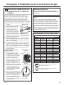
Monogram 30 and 36 Inch Stainless Steel Gas Cooktops Guide d'installation
- Taper
- Guide d'installation

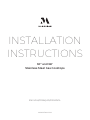
INSTALLATION
INSTRUCTIONS
30” and 36”
Stainless Steel Gas Cooktops
ENGLISH/FRANÇAIS/ESPAÑOL
MONOGRAM.COM

231-2001097 Rev. 0
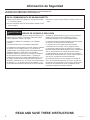
Safety Information
READ AND SAVE THESE INSTRUCTIONS
IN THE COMMONWEALTH OF MASSACHUSETTS
■ This product must be installed by a licensed plumber
or gas fitter.
■ Whenusingballtypegasshut-offvalves,theyshall
betheT-handletype.
■ Aflexiblegasconnector,whenused,mustnotexceed
5 feet.
WARNING FIRE OR EXPLOSION HAZARD
Iftheinformationinthismanualisnotfollowedexactly,
afireorexplosionmayresultcausingpropertydamage,
personal injury or death.
Installation must be performed by a qualified installer.
Read these instructions completely and carefully.
Installationofthiscooktopmustconformwithlocal
codes,orintheabsenceoflocalcodes,withtheNational
FuelGasCode,ANSIZ223.1/NFPA.54,latestedition.
InCanada,installationmustconformwiththecurrent
NaturalGasInstallationCode,CAN/CGA-B149.1or
thecurrentPropane(LP)InstallationCode,CAN/CGA-
B149.2,andwithlocalcodeswhereapplicable.This
producthasbeendesign-certifiedbyULaccording
toANSIZ21.1,latestadditionandCanadianGas
AssociationaccordingtoCAN/CGA-1.1latestaddition.
Wheninstallingagasappliancetheuseof
oldflexibleconnectorscancausegasleaksand
personalinjury.AlwaysuseaNEWflexibleconnector.
Leaktestingoftheapplianceshallbeconducted
according to the manufacturer instructions.
The cooktop must be electrically grounded in
accordancewithlocalcodesor,intheabsenceoflocal
codes,inaccordancewiththeNationalElectricalCode
(ANSI/NFPA70,latestedition).InCanada,electrical
groundingmustbeinaccordancewiththecurrentCSA
C22.1CanadianElectricalCodePart1and/orlocal
codes.SeeElectricalConnectionsinthissection.
Donotinstallthisproductwithanaircurtainhoodor
othercooktophoodthatoperatesbyblowingairdown
onthecooktop.Thisairflowmayinterferewithoperation
ofthegasburnersresultinginfireorexplosionhazard.
Questions? Call Monogram at 800.444.1845 or visit monogram.com
In Canada call 899.561.3344 or visit monogram.ca

31-2001097 Rev. 0 3
Safety Information
READ AND SAVE THESE INSTRUCTIONS
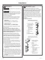
BEFORE YOU BEGIN
Read these instructions completely and carefully.
■ IMPORTANT —Savetheseinstructions
for local inspector’s use.
■ IMPORTANT —Observeallgoverning
codes and ordinances.
■ IMPORTANT —Removeallpacking
material and literature from appliance before
connecting gas and electrical supply to cooktop.
■ IMPORTANT —Toavoiddamageto
yourcabinets,checkwithyourbuilderorcabinet
suppliertomakesurethatthematerialsusedwill
notdiscolor,delaminateorsustainotherdamage.
This appliance has been designed in accordance
withtherequirementsofULandCSAInternational
andcomplieswiththemaximumallowablewood
cabinettemperaturesof194°F(90°C).
■ Note to Installer — Besuretoleavethese
instructionswiththeconsumer.
■ Note to Consumer —Keeptheseinstructionswith
yourOwner’sManualforfuturereference.
■ Servicer —Theelectricaldiagramisinanenvelope
inside of the cooktop.
■Properinstallationistheresponsibilityofthe
installer.
■Productfailureduetoimproperinstallationisnot
coveredunderwarranty.
■ForMonogramlocalserviceinyourarea,
1.800.444.1845.
■ForMonogramServiceinCanada,call
1.800.561.3344.
■ForMonogramPartsandAccessories,call
1.800.626.2002.
■Ifyoureceivedadamagedcooktop,youshould
contact your dealer.
MOBILE HOME - ADDITIONAL
INSTALLATION REQUIREMENTS
The installation of this product must conform to the
ManufacturedHomeConstructionandSafetyStandard,
Title24CFR,Part3280(formerlytheFederalStandard
forMobileHomeConstructionandSaftey,Title24,
HUDPart280).Whensuchstandardisnotapplicable,
usetheStandardforManufacturedHomeInstallations,
ANSIA225.1/NFPA501Aorwithlocalcodes.
InCanada,theinstallationofthisproductmust
conformwiththecurrentstandardsCAN/CSA-A240-
latestedition,orwithlocalcodes.
Whenthiscooktopisinstalledinamobilehome,
itmustbesecuredduringtransit.Anymethodof
securing the cooktop is adequate as long as it
conformstothestandardslistedabove.
IF SOLD OUTSIDE THE U.S. AND
CANADA
WARNING Ifyouwishtousethisproductwith
LiquefiedPetroleum(LP)gascontaininggreater
than10%butane,youmustpurchasethebutane
conversionkit#WB28X29976.Toorder,pleasecall
1.888.664.8403or1.787.276.4051.Failuretodoso
mayresultincarbonmonoxideorfirehazard.
VENT HOOD COMBINATIONS
Asuitableoverheadventhoodisrecommended.

431-2001097 Rev. 0
Contents
CONTENTS
Safety Information ....................................................... 2
Design Information
ProductDimensionsandClearances
for30”Models ............................................................ 5
ProductDimensionsandClearances
for36”Models ............................................................ 6
ProductDimensionsandClearances
for30”and36”Models ............................................... 7
Installation Options
CooktopInstallationWithAMonogram
DowndraftVent .......................................................... 8
CooktopInstallationOverAMonogram
WarmingDrawer ........................................................ 9
CooktopInstallationOvera27″or30″Monogram
SingleOven.............................................................. 10
Installation
MaterialsProvided ....................................................... 11
Tools Required ............................................................ 11
RemovePackaging ..................................................... 11
Cut the Countertop Opening ....................................... 12
Installing the Cooktop .................................................. 13
ConversionToPropane(LP)orNaturalGas .............. 13
GasSupply .................................................................. 14
ElectricalConnections ................................................. 15
CheckBurners ............................................................. 15
CheckSurfaceBurners ............................................... 15
WhenAllHookupsareCompleted .............................. 16
FinalizeInstallation ...................................................... 16
Installation Checklist .................................................... 16
Installation Instructions
Conversion to Propane (LP) or Natural Gas
ToolsYouWillNeedforConversion ........................... 17
ConverttheRegulator ................................................. 17
ChangeBurnerOrifices ............................................... 17
CheckSurfaceBurners ............................................... 18
AdjustingLowFlameSettingonCooktopBurners ..... 19
AdditionalInformation .................................................. 19

31-2001097 Rev. 0 5
Design Information
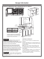
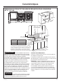
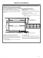
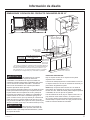
PRODUCT DIMENSIONS AND CLEARANCES FOR 30” MODELS
WARNING Installationswithoutahoodrequire
30”minimumtocombustibles.Acustomhood
installationwithexposedhorizontalcombustiblesurfaces
musthaveanAuto-Onfeature.Refertohoodinstallation
instructions for specific hood clearances.
Clearanceslessthan3-7/8”fromcutouttorearwall
requirethesurfaceoftheentirebackwallabovethe
cooktopandbelowthehoodtobecoveredwithanon-
combustible material. The material should be no less than
0.25”(6.4mm)thickflame-retardantmillboardcovered
withnolessthanNo.28MSGsheetmetal0.015”(0.38
mm)thick,0.015”(0.38mm)thickstainlesssteel,0.25”
(0.64mm)aluminumor0.020”(0.5mm)copper.
CAUTION Topreventdraftsfromaffectingburner
operation,sealallopeningsinfloorunderapplianceand
behindappliancewall.
ADDITIONAL CLEARANCES:
Allow12”minimumclearancetoanadjacentwallon
each side.
Workingareasadjacenttothecooktopshouldhave18”
minimumclearancebetweencountertopandthebottom
ofthewallcabinet.
NOTE:Allow7/16”minimumverticalclearancefrom
thecooktopbottom(or4-9/16”minimumdepthfrom
thecountertop)toanycombustiblesurfaces,suchasa
cabinetdrawer.
Forislandinstallation,maintain1-1/2in.minimumfrom
cutouttofrontand2-1/2in.minimumfromcutoutto
backedgeofcountertop.Maintain3in.minimumfrom
cutout to side edges of countertop.
1”
min.
12”
Gas
supply
line
30″orwidercabinet
base recommended
1-1/2″min.
from cutout
to front of
countertop
12″min.
from
cutout to
sidewall
Rear Wall
Min. Clearance From
Cutout to Rear Wall
Non-Combustible* 2-7/8”
Combustible 3-7/8”
19-5/8″
28-1/2″
12″min.
from cutout
tosidewall
16”Max.
30”Minimum
to Combustibles
18”Min.
30”
*AsdefinedintheNationalFuelGasCode(ANSIZ223.1,
CurrentEdition).Clearancesfromnon-combustiblematerials
arenotpartoftheANSIZ21.1scopeandarenotcertifiedby
UL.Clearanceslessthan3-7/8”mustbeapprovedbylocal
codesand/ortheauthorityhavingjurisdiction.
3-11/16″
21″
30″

631-2001097 Rev. 0
Design Information
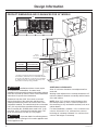
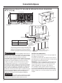
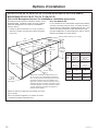
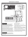
PRODUCT DIMENSIONS AND CLEARANCES FOR 36” MODELS
WARNING Installationswithoutahoodrequire
30”minimumtocombustibles.Acustomhood
installationwithexposedhorizontalcombustiblesurfaces
musthaveanAuto-Onfeature.Refertohoodinstallation
instructions for specific hood clearances.
Clearanceslessthan4-3/8”fromcutouttorearwall
requirethesurfaceoftheentirebackwallabovethe
cooktopandbelowthehoodtobecoveredwithanon-
combustible material. The material should be no less than
0.25”(6.4mm)thickflame-retardantmillboardcovered
withnolessthanNo.28MSGsheetmetal0.015”(0.38
mm)thick,0.015”(0.38mm)thickstainlesssteel,0.25”
(0.64mm)aluminumor0.020”(0.5mm)copper.
CAUTION Topreventdraftsfromaffectingburner
operation,sealallopeningsinfloorunderapplianceand
behindappliancewall.
ADDITIONAL CLEARANCES:
Allow12”minimumclearancetoanadjacentwallon
each side.
Workingareasadjacenttothecooktopshouldhave18”
minimumclearancebetweencountertopandthebottom
ofthewallcabinet.
NOTE:Allow7/16”minimumverticalclearancefrom
thecooktopbottom(or4-9/16”minimumdepthfrom
thecountertop)toanycombustiblesurfaces,suchasa
cabinetdrawer.
Forislandinstallation,maintain1-1/2in.minimumfrom
cutouttofrontand2-1/2in.minimumfromcutoutto
backedgeofcountertop.Maintain3in.minimumfrom
cutout to side edges of countertop.
1”
min.
12”
Gas
supply
line
36″orwidercabinet
base recommended
1-1/2″min.
from cutout
to front of
countertop
12″min.
from
cutout to
sidewall
Rear Wall
Min. Clearance From
Cutout to Rear Wall
Non-Combustible* 3-3/8”
Combustible 4-3/8”
19-1/8″
33-7/8″
12″min.
from cutout
tosidewall
16”Max.
30”Minimum
to Combustibles
18”Min.
36”
*AsdefinedintheNationalFuelGasCode(ANSIZ223.1,
CurrentEdition).Clearancesfromnon-combustiblematerials
arenotpartoftheANSIZ21.1scopeandarenotcertifiedby
UL.Clearanceslessthan3-7/8”mustbeapprovedbylocal
codesand/ortheauthorityhavingjurisdiction.
3-11/16″
21″
36″

31-2001097 Rev. 0 7
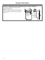
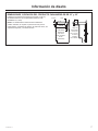
PRODUCT DIMENSIONS AND CLEARANCES FOR 30” AND 36” MODELS
ForAmericanswithDisabilitiesAct(ADA)Forward
ApproachInstallationOnly:
NOTE:Theenclosuremustbemadeofwoodmaterial.
Also,anaccesspanelisrequiredfortheelectricaloutlet,
pressureregulator,shut-offvalve,hold-downbrackets,
andservice.
Design Information
Allow5”
minimum
depth
betweenthe
countertop
and an
enclosure.
5”
7/16”
4-9/16”
DRAWER
14-4/5”Max
drawerdepth
(36”models
only)

831-2001097 Rev. 0
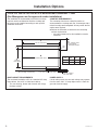
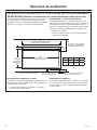
Installation Options
COOKTOP INSTALLATION WITH A MONOGRAM DOWNDRAFT VENT
(See Monogram.com for approved combo installations)
Theinstallationofthedowndraftventwiththiscooktop
requirescarefulconsideration.Boththecooktopand
theventmustbeinstalledaccordingtoeachspecific
installation instruction.
BASE CABINET REQUIREMENTS
Thecombinedinstallationwillfitinastandard24″deep
basecabinet.Usea30″orwiderbasecabinet.
– Theventhousing,blowerandductworkwilloccupy
the base cabinet.
COOKTOP REQUIREMENTS
Thecountertopmusthaveadeepflatsurfaceto
accommodatethecooktopandvent.Countertopswitha
rolledfrontedgeandbacksplashwillnotprovidetheflat
surface area required.
■ Reviewtheillustrationtodeterminethecountertop
surface requirements.
– Allcutoutclearancesforthisinstallationmustbe
observed.
POWER SUPPLY
Iflocalcodespermit,theventandcooktopmayoperate
fromthesame120V,15ampduplexoutlet.Locatethe
gas and electrical supply.
ABCD
30” 28-1/2” 19-5/8” 2-7/8”
36” 33-7/8” 19-1/8” 3-3/8”
C
Cooktop
cutout depth
2-3/4″
A
28-1/2″ventcutout
1/8″
gap
D
Min.cooktopcutout
torearvertical
combustible surface
12″min.cutoutto
wall,bothsides
1-1/2″min.clearancetocutout
Front edge of countertop
B
Cooktop area cutout

31-2001097 Rev. 0 9
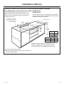
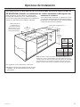
Installation Options
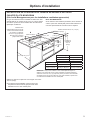
COOKTOP INSTALLATION OVER A MONOGRAM WARMING DRAWER
(See Monogram.com for approved combo installations)
Thesecooktopsmaybeinstalledovera30″or27″
WarmingDrawer.Boththecooktopandthewarming
drawermustbeinstalledaccordingtoeachspecific
installation instruction.
Usea30″orwiderbasecabinet.
■Plangassupplylocationcarefullytoavoidinterference
withthewarmingdrawer.
POWER SUPPLY
Iflocalcodespermit,thecooktopandwarmingdrawer
mayoperatefromthesame120Vduplexoutlet.Referto
installation instructions for details.
Install2x4or2x2anti-tip
block against rear cabinet
wall9″fromcutoutfloor
to bottom of block
23-1/2″min.
B
Cooktop C1-1/2″min.
1-1/2″cabinettop
5-1/2″min.
NOTE:WheninstallingaMonogramWarmingDrawerbelow
acooktop,asolidbarriermustbeinstalledatleast1″fromthe
lowestpointofthebottomofcooktopburnerboxtothetopof
cutout.SeeWarmingDrawerInstallationInstructionsfordetails.
36″
countertop
height
9-1/4″
A
25″
9″
Cooktop B C
30” 28-1/2” 19-5/8”
36” 33-7/8” 19-1/8”
Warming
Drawer A
30” 28-1/2”
27” 25-1/2”

10 31-2001097 Rev. 0
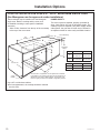
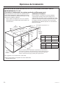
Installation Options
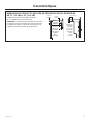
COOKTOP INSTALLATION OVER A 27″ OR 30″ MONOGRAM SINGLE OVEN
(See Monogram.com for approved combo installations)
ThesecooktopsmaybeinstalledovertheMonogram
singleoven.Boththecooktopandtheovenmust
be installed according to each specific installation
instruction.
– Allow4″Min.clearancefromthetopofthecountertop
tothetopoftheovencutout.
Usea30″orwiderbasecabinet.
■Forbestappearance,thecooktopshouldbecentered
overtheoven.
POWER SUPPLY
Theovenrequiresaseparate,properlygrounded20
Amp,3-wire208or240volt,60Hzpowersupply.The
cooktoprequiresaseparate120Vpowersupply.Where
codespermit,thegasshut-offvalvemaybelocatedin
an adjacent cabinet or other easily accessible location.
Usetwo2x4’sorequivalentrunnersspaced25″centerline
tocenterlineintheopeningandflushwithtopoftoekick.Or
elevatetheovenfloortodesiredheight.Thesupportmust
belevel,rigidlymountedandcapableofsupporting200lbs.
23-1/2″min.
C
Cooktop
D1-1/2″min.
1-1/2″cabinettop
4″min.
36″
countertop
height
B
A
25″
25″
C
L
C
L
Cooktop C D
30” 28-1/2” 19-5/8”
36” 33-7/8” 19-1/8”
4″ high
toekick
Ovens A B
30” 28-1/2″min.
28-5/8″max.
27-1/4″min.
27-5/16″max.
27” 25″min.
25-1/4″max.
27-5/8″min.
28-1/8″max.

31-2001097 Rev. 0 11
Installation Information
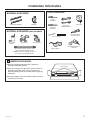
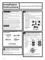
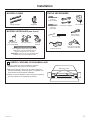
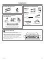
MATERIALS REQUIRED (not provided)
MATERIALS PROVIDED
Shut-OffValvePipeFittings
5-footmaximumlength,5/8”O.D.CSA-
approvedflexiblemetalgassupply
NOTE:Purchasenewflexibleline;donot
usepreviouslyusedflexiblegasline.
PipeThread
Sealant
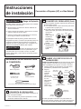
1 REMOVE PACKAGING
■Removepackagingtapeandfoam.Disposeof
packaging materials properly.
■Slidethecooktopoutoftheendofthebox.Remove
packagingmaterials,grateboxes,regulatorand
literature package from the cooktop before beginning
installation.
■Usetheshippingcartonasapadtoprotectcustomer
countertops or flooring.
Regulator
2Hold-DownBrackets
TOOLS REQUIRED
Flat-blade
screwdriver
Pipewrenches(2)
(oneforbackup)
Phillips
screwdriver
Open-endor
adjustablewrench
Pencilandruler
SaberSaw
SafetyGlasses
1/8″DrillBit&Electricor
HandDrill
Foam support

12 31-2001097 Rev. 0
Installation
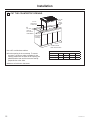
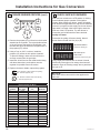
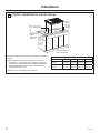
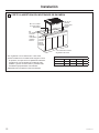
2 CUT THE COUNTERTOP OPENING
Usea30″orwiderbasecabinet.
■ Cuttheopeninginthecountertop.Toensure
accuracy,itisbesttomakeatemplateforthe
opening.Makesurethesidesoftheopeningare
parallelandtherearandfrontcutsareexactly
perpendicular to the sides.
■ Observeallminimumclearances.
Dimensions
A B C D
30”Cooktop 2-7/8” 19-5/8” 28-1/2” 30”
36”Cooktop 3-3/8” 19-1/8”
33-7/8”
36”
12″min.
from cutout
tosidewall
1-1/2″min.
from cutout
to front of
countertop
A
min. from
cutout to
rearvertical
combustibles
12″min.
from
cutout
to side
wall
C
D
orwidercabinet
base recommended
B

31-2001097 Rev. 0 13
Installation
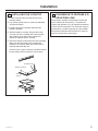
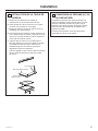
4 CONVERSION TO PROPANE (LP)
OR NATURAL GAS
The pressure regulator and the burner orifices are
set for natural gas at the factory. To operate the
cooktopwithpropane(LP),theregulatorandburner
orificesmustbeconverted.Theconversionmustbe
performedbyaqualifiedpropane(LP)gasinstaller.
Keep these instructions and all orifices in case you
wanttoconvertbacktonaturalgas.
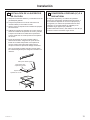
3 INSTALLING THE COOKTOP
A.Locateelectricaloutletandgasshut-offvalve
beneath cabinet.
B.Laycooktopupsidedownonatowelortablecloth
coveredcountertop.
C.Locateandremovehold-downbracketsfrom
literature package.
D.Attachbracketstocooktop.Removethescrew
fromthesideofthecooktopandscrewthehold-
downbrackettothesideofthecooktopunit.
Repeat for opposite side of cooktop.
E.Insertthecooktopcenteredintothecutoutopening.
Makesurethefrontedgeofthecountertopis
paralleltothecooktop.Makefinalcheckthatall
required clearances are met.
Oncetheunitisinplace,screwthehold-downbracket
into the cabinet sides to secure the unit into place.
Cooktop
Pre-drilledhole
BottomofCooktop
Cooktop
Surface

14 31-2001097 Rev. 0
Installation
5 GAS SUPPLY
WARNING FireHazard:Donotuseaflameto
check for gas leaks.
WARNING ExplosionHazard:Donotexceed
25ft-lbsoftorquewhenmakinggaslineconnections.
Overtighteningmaydamagethepressureregulator
resultinginfireorexplosionhazard.
Gas Pressure Regulator
You must use the gas pressure regulator supplied
withthiscooktop.Forproperoperationstheinlet
pressuretotheregulatorshouldbeasfollows:
Natural Gas:
Minimumpressure:6”ofWaterColumn
Maximumpressure:13”ofWaterColumn
Propane (LP) Gas:
Minimumpressure:11”ofWaterColumn
Maximumpressure:13”ofWaterColumn
If you are not sure about the inlet pressure contact
local gas supplier.
Shut off the main gas supply valve before
disconnecting the old cooktop and leave it off
until the new hook-up has been completed. Don’t
forget to relight the pilot on other gas appliances
when you turn the gas back on.
Becausehardpipingrestrictsmovementofthe
cooktop,theuseofaCSAInternational-certified
flexiblemetalapplianceconnectorisrecommended
unlesslocalcodesrequireahard-pipedconnection.
Ifthehardpipingmethodisused,carefullyalign
thepipe;thecooktopcannotbemovedafterthe
connection is made.
Topreventgasleaks,putpipethreadsealanton,or
wrappipethreadtapewithTeflon*aroundallmale
(external)pipethreads.
A. Installprovidedpressureregulatordirectlytothe
gasinletpipeofthecooktop.Refertothearrow
onthebackoftheregulatorforgasflowdirection.
Ensurethefrontoftheregulatorisfacingtowards
thecabinetfront,easilyaccessiblethroughthe
cabinet doors.
B. Installamanualshut-offvalveinthegaslineina
location easily accessible through the cabinet doors.
C. Whenallconnectionshavebeenmade,ensureall
gas controls are in the off position and turn on the
maingassupplyvalve.Usealiquidleakdetector
at all joints and connections to check for leaks in
the system.
*Teflon:RegisteredtrademarkofDuPont
5 GAS SUPPLY (cont.)
Whenusingpressuresgreaterthan1/2psigto
pressuretestthegassupplysystemoftheresidence,
disconnectthecooktopandindividualshut-offvalve
fromthegassupplypiping.Whenusingpressures
of1/2psigorlesstopressuretestthegassupply
system,simplyisolatethecooktopfromthegas
supplysystembyclosingtheindividualshut-offvalve.
Whencheckingforproperoperationoftheregulator,
theinletpressuremustbeatleast1”greaterthanthe
operating(manifold)pressureasgivenonratinglabel
of product.
CONNECTOR HOOKUP
TYPICALINSTALLATIONWITHNO
OBSTRUCTIONBELOWCOOKTOP
A
B
C
D
F
G
E
A. 3/8”NPTx3/8”NPT
threaded adapter fitting
(onsomemodels)
B. Regulatorprovided
withunit:
• Outlet-3/8”NPT
female pipe thread
• Inlet-1/2”NPT
female pipe thread
C. Adapter
D. Flexibleconnector
E. Adapter
F. Manualshut-offvalve
G. Gaspipe1/2”or3/4”
ALTERNATEINSTALLATIONWITH
OBSTRUCTIONBELOWCOOKTOP
A. 3/8”NPTx3/8”NPT
threaded adapter fitting
(onsomemodels)
B. E lbow
C. Adapter
D. Flexibleconnector
(allowspassagethrough
cabinetwall)
E. Adapter
F. Regulatorprovidedwithunit:
• Outlet-3/8”NPT
female pipe thread
• Inlet-1/2”NPT
female pipe thread
G. Gas pipe
H. Manualshut-offvalve
I. Gaspipe1/2”or3/4”
A
B
C
D
F
G
E
I
H

31-2001097 Rev. 0 15
Installation
6 ELECTRICAL CONNECTIONS
WARNING ShockHazard:Thisappliancemust
be properly grounded. Failure to do so can result in
electric shock.
ElectricalRequirements-120-volt,60Hertz,properly
groundeddedicatedcircuitprotectedbya15-ampor
20-ampcircuitbreakerortimedelayfuse.
NOTE:Useofautomatic,wireless,orwiredexternal
switchesthatshutoffpowertotheappliancearenot
recommended for this product.
Grounding
Thepowercordofthisapplianceisequippedwith
athree-prong(grounding)plugwhichplugsintoa
standardthree-pronggroundingwallreceptacleto
minimizethepossibilityofelectricshockhazardfrom
this appliance.
Thecustomershouldhavethewallreceptacleand
circuit checked by a qualified electrician to make sure
the receptacle is properly grounded.
Whereastandardtwo-prongwallreceptacleis
encountered,itisthepersonalresponsibilityand
obligationofthecustomertohaveitreplacedwitha
properlygroundedthree-prongwallreceptacle.
DONOT,UNDERANYCIRCUMSTANCES,CUTOR
REMOVETHETHIRD(GROUND)PRONGFROM
THEPOWERCORD.DONOTUSEANADAPTER.
DONOTUSEANEXTENSIONCORD.
GroundFaultCircuitInterrupters(GFCI’s)arenot
required or recommended for gas cooktop receptacles.
Performanceofthecooktopwillnotbeaffectedif
operatedonaGFCI-protectedcircuitbutoccasional
nuisance tripping of the GFCI breaker may occur.
Ensureproper
groundexists
before use
7 CHECK BURNERS
WARNING FireorExplosionHazard:Donot
operatetheburnerwithoutallburnerpartsinplace.
A. Burners-Place
surface burners
into corresponding
positions on cooktop.
B. Caps-Placecapson
propersizeburner.
C. Grates-Theleftandrightgratesare
interchangeable.Placethegratesonthecooktop.
Placethetwosidegratessothatacontinuous
“line”isformedwiththecenterribsofbothgrates.
Makesurebothgratesarestableandlevel.
8 CHECK SURFACE BURNERS
PushandturnaknobtotheLITEposition.Aclicking
sound indicates proper operation of the ignition
system.Whenlightinganyburner,sparkswillappear
atallburnersbutgasflowsfromonlytheoneselected.
Onceairispurgedfromthesupplyline,burnershould
lightwithin4seconds.Afterburnerlights,rotatethe
knoboutoftheLITEposition.Tryeachburnerin
successionuntilallburnershavebeenchecked.
Quality of Flames
Determinethequalityofflamesvisually.Normal
burnerflamesshouldlooklike(A)or(B).
Long,brightyellowflamesarenotnormal.Normal
flamesmayshowsignsofanorangetintwhenwell
heated or signs of flickering orange due to particles in
the gas or air.
(A) Soft blue flames—
Normalfornaturalgas
(B) Yellow tips on
outer cones—
Normalforpropane(LP)gas
BurnerCapNotProperlySeated
BurnerCapProperlySeated

16 31-2001097 Rev. 0
Installation
FINALIZE INSTALLATION
Placetheburnergratesovertheburners.Thegrates
should be seated and should not rock.
WHEN ALL HOOKUPS ARE
COMPLETED
Checkthatallpackingmaterialsandtapehave
beenremoved.Thiswillincludetapeonmetalpanel
undercontrolknobs(ifapplicable),adhesivetape,
wireties,cardboardandprotectiveplastic.Failureto
removethesematerialscouldresultindamagetothe
appliance once the appliance has been turned on and
surfaceshaveheated.
INSTALLATION CHECKLIST
■MakesureallcontrolsareleftintheOFFposition.
■Makesuretheflowofcombustionandventilationair
to the cooktop is unobstructed.
■Recheck Steps:
Double check to make sure everything in this
manual has been completed. Rechecking steps
will ensure safe use of the cooktop.
NOTE: The rating plate is located on the bottom of
the cooktop. The model and serial number may also
befoundbehindtheleftknobandisvisiblewhenthe
knob is pulled off.

31-2001097 Rev. 0 17
Conversion to Propane (LP) or Natural Gas
WARNING Explosion Hazard
Deathorseriousinjurycanresultfromfailuretofollow
these instructions.
■ Servicebyaqualifiedservicetechnicianonly.
■ Shutoffgassupplyanddisconnectpowerbefore
servicing.
■ Reconnectallgroundingdevicesafterservice.
■ Replaceallpartsandpanelsbeforeoperating.
The pressure regulator and the burner orifices are
factorysetfornaturalgas.Tooperatethecooktopwith
propane(LP)gas,theregulatorandburnerorifices
mustbeconvertedbyfollowingtheseinstructions:
WARNING Do not operate the cooktop before
convertingtheburnerorificesforthegastobeused.
Failuretodosocouldcausehighflamesandtoxic
fumeswhichcanresultinseriousinjury.
TOOLS YOU WILL NEED FOR
CONVERSION
1
CONVERT THE REGULATOR (Cont.)
B. Adjustthepressureregulatorbythefollowing
instructions:
■Unscrewthecap.
■Carefullylookatthespringretainertolocatethe
NATorpropane(LP)position.
■Turnthespringretaineroverbyrotatingit90
deg.,pullitfromthecap,turnthespringretainer
oversothat
propane(LP)is
showing,insert
it back into the
cap,andthen
rotateit90deg.
into position.
■Screwthecap
back onto the
regulator and
tighten.
1 CONVERT THE REGULATOR
Disconnectallelectricalpoweratthemaincircuit
breakerorfusebox.
A. Shutoffthegassupplytothecooktopbyclosing
themanualshut-offvalve.
2 CHANGE BURNER ORIFICES
INSTALLATION TIP: Firstremoveallorificesand
thenstartreplacingthem.Thiswillhelptopreventthe
possibility that some may not be replaced.
A. Removetheburnergrates,burnercapsandburner
heads.
B. Loosenthe
top burner
orifices using
a7mmnut
driver.Use
small pliers
to carefully
lift out the
orifices.
Themainorificeislocatedlowinthecenterofthe
burner,whilethesimmerorificeislocatedhigher
beside the center of the burner.
Installation
Instructions
SafetyGlasses
SmallFlat-HeadScrewdriver
(2to2.4mmor3/32”tipsize,60mmlong)
CrescentWrench
1/4”and7mmNutdrivers SmallPliers
Main
Orifice
Simmer
Orifice
Burner
cap
Burner
head
Burnerbase
Spark
igniter
Burner
caps
Burner
head
Multi-ring
(onsomemodels)
NAT
LP NAT
LP
NAT
LP NAT
LP
Gasket
Cap
Spring
retainer
Propane(LP)
position
NAT.
position
Pressureregulator
Spark
igniter

18 31-2001097 Rev. 0
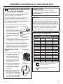
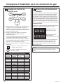
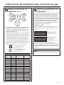
Installation Instructions for Gas Conversion
2
CHANGE BURNER ORIFICES (cont.)
A. Removethepropane(LP)orificesfromthebracket
attached to the regulator. The top and side surface
oftheorificesareengravedforidentification.Use
the table and figure to determine the placement of
thepropane(LP)orifices.
B. Usinga7mmor9/32”nutdriver,installthe
propane(LP)orificesintheirpreciselocations.
Topreventleakage,makesuretheorificesare
securelyscrewedintothegasinjets.
C. Install the old orifices into the metal bracket along
withtheseinstructions,andreplaceontothe
regulatorforpossiblefutureconversion.
D. Replacetheburnerheads,capsandtopgrates.
3 CHECK SURFACE BURNERS
PushandturnaknobtotheLITEposition.Aclicking
sound indicates proper operation of the ignition
system.Whenlightinganyburner,sparkswillappear
atallburnersbutgasflowsfromonlytheoneselected.
Onceairispurgedfromthesupplyline,burnershould
lightwithin4seconds.Afterburnerlights,rotatethe
knoboutoftheLITEposition.Tryeachburnerin
successionuntilallburnershavebeenchecked.
Quality of Flames
Determinethequalityofflamesvisually.Normal
burnerflamesshouldlooklike(A)or(B).
Long,brightyellowflamesarenotnormal.Normal
flamesmayshowsignsofanorangetintwhenwell
heated or signs of flickering orange due to particles in
the gas or air.
BURNER OUTPUT RATINGS: BTU/HR
Propane (LP) Gas 10” W.C.P.
BURNER BTU RATE
ORIFICE SIZE
(mm) MARKING
LF 10,000
Main N/A 0.88 88XL
Simmer N/A 0.34 34SL
LR 10,000
Main N/A 0.88 88XL
Simmer N/A 0.34 34SL
C18,000
C1 N/A 0.686 69L
C1 N/A 0.686 69L
C1 N/A 0.686 69L
C2 N/A 0.41 41L
RR 10,000
Main N/A 0.88 88XL
Simmer N/A 0.34 34SL
RF 12,000
Main N/A 0.97 97XL
Simmer N/A 0.34 34SL
(A) Soft blue flames—
Normalfornaturalgas
(B) Yellow tips on
outer cones—
Normalforpropane(LP)gas
95-Denotes0.95mmorificesizeopening
L-Denotespropane(LP)
95
III
108-Denotes1.08mmorificesizeopening
XL-Denotespropane(LP)
C1C1
C2
C1
LF
RR
RF
C
LR Main
Simmer
Main
Simmer
Main
Simmer
Main
Simmer
NOTICE:
Savetheseorificesremovedfromtheappliancefor
future use.

31-2001097 Rev. 0 19
4 ADJUSTING LOW FLAME SETTING
ON COOKTOP BURNERS
Thisprocedureadjuststhelowflowoftheupperring
offlamesoneachofthe4dualstackburners.The
lowerrowofflamesisnotadjustable.
Lowsettingadjustmentsmustbemadewith2other
burners in operation on a medium setting. This
procedurepreventsthelowflamefrombeingsettoo
low,resultingintheflamebeingextinguishedwhen
other burners are turned on.
A. Turnonsurfaceburnerstomediumsetting.
B. Turntheknobontheburner
beingadjustedto“LO”.
C. Removetheknobandinsert
asmallflatbladescrewdriver
inthevalveshaftasshown.
Turncounterclockwiseasfar
aspossiblewhilemaintaining
a stable flame. Repeat for all
valves.
D. Ifflameappearstoolowor
unstable,slowlyturnadjustmentscrewclockwise
untilastableflameexistsforeachburner.
E. Additionally,foreachburnerbeingadjusted,
quicklyopenandclosethecabinetdoorswhile
observingtheflame.Ifflameisextinguished,turn
adjustmentscrewclockwiseforalargerflame.
Repeat door openings until flame is stable.
Multi-Ring Burner (on some
models)
■ TurnonburnertoMEDsetting
to adjust the outer ring. Turn
the outer ring adjustment
screw(inthecenterofthe
valveshaft)counterclockwise
so that the outer ring flames
barelycurloverthetopedge
of the burner cap.
■ TurnonburnertoSIMsetting
to adjust the center ring. Turn
counterclockwise
as far as
possiblewhilemaintaininga
stable flame.
■ Openandclosethecabinet
doorswhileobservingthe
flame.Ifflameisextinguished,
turnadjustmentscrewclockwise
for a larger flame. Repeat door
openings until flame is stable.
SPECIAL NOTE:
To convert the cooktop back to natural gas,
reverse the instructions given in making propane
(LP) adjustments.
NOTICE:
Oncetheconversioniscompleteandconfirmed,fill
outthepropane(LP)stickerandincludeyourname,
organizationanddateconversionwasmade.Applythe
sticker to the cooktop near the regulator to alert others
inthefuturethatthisappliancehasbeenconvertedto
propane(LP).Ifconvertingbacktonaturalgasfrom
propane(LP),pleaseremovethestickersoothers
knowtheapplianceissettousenaturalgas.
ADDITIONAL INFORMATION
Installation Instructions for Gas Conversion
Centeradjustmentscrew
forallburnersexceptthe
Multi-RingBurner
Inside shaft
Round Burners
Flames
BurnerCap
Multi-Ring Burner
BURNER OUTPUT RATINGS: BTU/HR
NG (Natural) Gas 5” W.C.P.
BURNER BTU RATE
ORIFICE SIZE
(mm) MARKING
LF 10,000
Main N/A 1.28 128XN
Simmer N/A 0.51 51SN
LR 10,000
Main N/A 1.28 128XN
Simmer N/A 0.51 51SN
C20,000
C1 N/A 1.1 110N
C1 N/A 1.1 110N
C1 N/A 1.1 110N
C2 N/A 0.63 63N
RRMain 10,000
Main N/A 1.28 128XN
Simmer N/A 0.51 51SN
RF 12,000
Main N/A 1.45 145XN
Simmer N/A 0.51 51SN
Adjustmentscrew
for center ring
Adjustmentscrew
for outer ring
Multi-Ring Burner
198-Denotes1.98mmorificesizeopening
N-DenotesNaturalGas
198
III
N
190-Denotes1.90mmorificesizeopening
XN-Denotesnaturalgas

NOTE: Whileperforminginstallationsdescribedinthisbook,
safetyglassesorgogglesshouldbeworn.
NOTE: Productimprovementisacontinuingendeavorat
GEAppliances.Therefore,materials,appearanceand
specificationsaresubjecttochangewithoutnotice.
PrintedintheUnitedStates
31-2001097Rev.0
04-22GEA
La page est en cours de chargement...
La page est en cours de chargement...
La page est en cours de chargement...
La page est en cours de chargement...
La page est en cours de chargement...
La page est en cours de chargement...
La page est en cours de chargement...
La page est en cours de chargement...
La page est en cours de chargement...
La page est en cours de chargement...
La page est en cours de chargement...
La page est en cours de chargement...
La page est en cours de chargement...
La page est en cours de chargement...
La page est en cours de chargement...
La page est en cours de chargement...
La page est en cours de chargement...
La page est en cours de chargement...
La page est en cours de chargement...
La page est en cours de chargement...
La page est en cours de chargement...
La page est en cours de chargement...
La page est en cours de chargement...
La page est en cours de chargement...
La page est en cours de chargement...
La page est en cours de chargement...
La page est en cours de chargement...
La page est en cours de chargement...
La page est en cours de chargement...
La page est en cours de chargement...
La page est en cours de chargement...
La page est en cours de chargement...
La page est en cours de chargement...
La page est en cours de chargement...
La page est en cours de chargement...
La page est en cours de chargement...
La page est en cours de chargement...
La page est en cours de chargement...
La page est en cours de chargement...
La page est en cours de chargement...
-
 1
1
-
 2
2
-
 3
3
-
 4
4
-
 5
5
-
 6
6
-
 7
7
-
 8
8
-
 9
9
-
 10
10
-
 11
11
-
 12
12
-
 13
13
-
 14
14
-
 15
15
-
 16
16
-
 17
17
-
 18
18
-
 19
19
-
 20
20
-
 21
21
-
 22
22
-
 23
23
-
 24
24
-
 25
25
-
 26
26
-
 27
27
-
 28
28
-
 29
29
-
 30
30
-
 31
31
-
 32
32
-
 33
33
-
 34
34
-
 35
35
-
 36
36
-
 37
37
-
 38
38
-
 39
39
-
 40
40
-
 41
41
-
 42
42
-
 43
43
-
 44
44
-
 45
45
-
 46
46
-
 47
47
-
 48
48
-
 49
49
-
 50
50
-
 51
51
-
 52
52
-
 53
53
-
 54
54
-
 55
55
-
 56
56
-
 57
57
-
 58
58
-
 59
59
-
 60
60