Moxa AWK-4252A Series Read Out Instrumentation Guide d'installation
- Taper
- Guide d'installation

P/N: 1802042520010
*1802042520010*
AWK-4252A Series
Quick Installation Guide
Moxa AirWorks
Version 1.0, September 2022
Technical Support Contact Information
www.moxa.com/support
2022 Moxa Inc. All rights reserved.

- 2 -
Overview
The AWK-4252A Series is an industrial-grade AP/bridge/client with IEEE
802.11ac Wave 2 technology. This Series features concurrent dual-band
Wi-Fi data transmissions up to 400 Mbps (2.4 GHz mode) and 867 Mbps
(5 GHz mode) simultaneously, meeting the speed and flexibility
requirements for industrial applications. In addition, the built-in dual
band pass filter and the wide-temperature design ensure the reliability
and continuous operation in harsh environments. The dual redundant
DC power inputs enhance availability while support for PoE power
provides more flexibility and simplifies field-site deployments.
Meanwhile, backwards compatibility with 802.11a/b/g/n makes the
AWK-4252A the ideal solution for constructing a versatile wireless data
transmission system.
Hardware Setup
This section covers the hardware setup for the AWK-4252A.
Package Checklist
Moxa’s AWK-4252A is shipped with the following items. If any of these
items is missing or damaged, please contact your customer service
representative for assistance.
• 1 x AWK-4252A wireless AP/client
• 2 x 2.4/5 GHz antennas: ANT-WDB-ARM-0306
• Wall-mount kit
• 1 x Field-installable power plug
• 2 x Field-installable RJ45 plugs
• Quick installation guide (printed)
• Warranty card
Optional Mounting Accessories (Sold Separately)
• DIN-rail kit including 8 screws (M3x6)

- 3 -
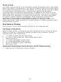
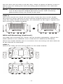
Panel Layout of the AWK-4252A
1. Antenna connector 2
2. Antenna connector 1
3.
System LEDs: PWR, LAN2,
LAN1, 2.4GHz, 5 GHz, SYS
4. Grounding screw (MS5)
5. Power connector (5 pin
M12 A-coded male)
6.
Digital IO connector (8 pin
M12 A coded female)
7. USB Type A connector
8. Console port (RJ45)
9. LAN2
10/100/1000BaseT(X)
ports RJ45 port
10.
LAN1
10/100/1000BaseT(X)
ports RJ45 port
11.
Reset button
12.
Waterproof vent

- 4 -
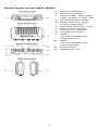
Mounting Dimensions
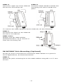
Wall Mounting
For some applications, it may be more convenient to mount the AWK-
4252A to a wall, as illustrated below.
STEP 1:
Align the wall
-mounting
plates to the wall
-
mounting
screw holes on the rear
panel, the
n attach the wall-
mounting plates with the
M5
x 7.5 mm screws, as
shown in the adjacent
diagrams
.
STEP 2:
Mounting the
AWK-4252A to a wall requires 4
screws.
Use
the AWK-4252A device with the wall-mounting
plates attached as a guide to mark the correct
location of the
4 screws on the wall
. The heads of the
screws should be less than 6.0 mm in diameter, the
shafts should be less than 3.5 mm in diameter,
and
the
screw length should be at least 15 mm, as shown
in the figure on the right.

- 5 -
Do not drive the screws in all the way—leave a space of about 2 mm to
allow room for sliding the wall-mounting panel between the wall and
the screws.
NOTE
Test the screw head and shank size by inserting the screws
into
one of the keyhole shaped apertures of the wall
-mounting
plates before they are fixed to the wall.
STEP 3:
Once the screws are fixed into the wall, insert the four screw heads
through the large opening of the keyhole-shaped apertures, and then
slide the AWK-4252A downwards, as indicated on the right. Tighten the
four screws for added stability.
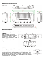
DIN-rail Mounting (Optional)
The DIN-rail mounting kit, which can be bought separately, allows the
AWK-4252A to be installed onto a DIN rail for additional flexibility.
Mount the AWK-4252A onto a corrosion-free mounting rail that adheres
to the EN 60715 standard.
STEP 1:
Attach the DIN-rail mounting plates to the AWK-4252A.

- 6 -
STEP 2:
Insert the upper lip of the DIN
-rail
kit into the mounting rail.
STEP 3:
Press the
AWK-4252A towards the
mounting rail until it snaps into
place.
To remove the AWK-4252A from the DIN rail, do the following:
STEP 1:
Pull down the latch on the DIN
-rail
kit with a screwdriver.
STEP 2 & 3:
Slightly pull the
AWK-4252A
forward and lift it up to remove it
from the mounting rail.
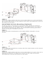
PK-DC2DOF Pole Mounting (Optional)
It may be more convenient to mount the AWK-4252A on a pole for
some applications, as illustrated below.
STEP 1:
Attach the pole-mounting kit to the AWK-4252A using M5 x 15.7 mm
screws.

- 7 -
STEP 2:
Install the AWK-4252A with the mount assembled on a pole and fasten
the screws M8 screws on the bracket of the pole-mounting kit to secure
the device to the pole.
PK-DC2DOF-02 Pole Mounting (Optional)
It may be more convenient to mount the AWK-4252A on a pole for
some applications, as illustrated below. The edges of the iron rings on
the pole-mounting kit are sharp. We recommend wearing protective
gloves during the installation process.
STEP 1:
Attach the pole-mounting kit to the AWK-4252A using M4 x 8 mm
screws.
STEP 2:
Use a flathead screwdriver to loosen the hex head screws on the mount
to release the rings.
STEP 3:
Install the AWK-4252A with the mount assembled on a pole, then use a
flathead screwdriver to fasten the screws on the rings of the pole-
mounting kit to secure the device to the pole.

- 8 -
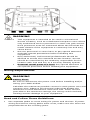
WARNING
•
This equipment is intended to be used in a Restricted
Access Location, such as a dedicated computer room
where
only authorized service personnel or
users can gain access.
Such personnel must be instructed about the fact that the
metal chassis of the equipment is extremely hot and may
cause burns.
•
Service personnel or users have to pay special attention
and take special precautions before handling this
equipment.
•
Only authorized, well-trained professionals should be
allowed to access the restricted access location. Access
should be controlled by the authority responsible for the
location with lock and key or a security identity system.
•
External metal parts are hot!! Pay special attention or
use special protection before handling the equipment.
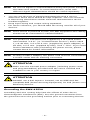
Wiring Requirements
WARNING
Safety First!
Be sure to disconnect the power cord before installing and/or
wiring your
AWK-4252A.
Calculate the maximum possible current in each power wire and
common wire. Observe all electrical codes that dictate the
maximum current allowed for each wire size. If the
current
goes above the maximum ratings, the wiring could overheat,
causing serious damage to your equipment.
Read and Follow These Guidelines:
• Use separate paths to route wiring for power and devices. If power
wiring and device wiring paths must cross, make sure the wires are
perpendicular at the crossing point.

- 9 -
NOTE
Do not run signal or communications wiring and power wiring in
the same wire co
nduit. To avoid interference, wires with
different signal characteristics should be routed separately.
• You can use the type of signal transmitted through a wire to
determine which wires should be kept separate. The rule of thumb
is that wiring that shares similar electrical characteristics can be
bundled together.
• Keep input wiring and output wiring separated.
• For future reference, you should label the wiring used for all of your
devices.
NOTE
If the device is powered by PoE, the PSE equipment
and cabling
should not be connected to outside facilities.
NOTE
The product is intended to be supplied by a UL
Listed Power
Unit marked "L.P.S." (or "Limited Power Source") and is rated
1) 12
-48 VDC, 2.2-0.55 A min. (supplied by power adapter) or
48
VDC, 0.5 A min. (supplied by PoE), Tma = 75°C. If you
need
further
assistance with purchasing the power source, please
contact Moxa for further information.
NOTE
If using a Class I adapter, the power cord must be connected to
a socket-outlet with an earthing connection.
ATTENTION
Make sure
the external power adapter (including power cords
and plug assemblies) provided with the unit is certified and
suitable for use in your country or region.
ATTENTION
DO NOT
use a PoE Injector. Instead, use an IEEE 802.3at
compliant PSE (Power Sourcing Equipment) for PoE (Power over
Ethernet) devices.
Grounding the AWK-4252A
Grounding and wire routing help limit the effects of noise due to
electromagnetic interference (EMI). Run the ground connection from
the ground screw to the grounding surface prior to connecting devices.

- 10 -
ATTENTION
This product is intended to be mounted to a well
-grounded
mounting surface, such as a metal panel.
The potential
difference between any two
grounding points must be zero. If
the potential difference is NOT zero, the product could be
permanently damaged.
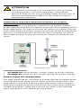
Installations with Cable Extended Antennas for Outdoor
Applications
If an AWK device or its antenna is installed in an outdoor location,
proper lightning protection is required to prevent direct lightning strikes
to the AWK device. In order to prevent the effects of coupling currents
from nearby lightning strikes, a lightning arrester should be installed as
part of your antenna system. Ground the device, antenna, as well as
the arrester properly to provide maximum outdoor protection for the
device.
Arrester Accessories
• SA-NMNF-02: Surge arrester, N-type (male) to N-type (female)
• SA-NFNF-02: Surge arrester, N-type (female) to N-type (female)
Power Input Pin Assignment
The AWK-4252A can be connected to an IEEE 802.3at compliant Power
over Ethernet (PoE) power source. When powered via DC power, the
AWK-4252A comes with a M12 A-coded 5-pin power input connector
located on the bottom panel of the device. The power input connector
contains dual power inputs and a ground pin. Refer to the following
figure and table for the detailed pin assignment.

- 11 -
Pin
Power Input
1
V1+
2
V2+
3
V1-
4
V2-
5
GND
ATTENTION
If the
AWK-4252A
is connected to a motor or other similar type
of equipment, be sure to use power isolation protection. Before
connecting the
AWK-4252A to the DC power inputs, make sure
the DC power source voltage is stable.
Wiring the Digital Inputs and Relay Contact (Digital
Output)
The AWK-4252A has two sets of digital input—DI1 and DI2. Each DI
comprises of two contacts of the 8-pin M12 connector on the AWK-
4252A’s bottom panel. These two digital inputs can be connected to
digital-output-enabled sensors for on-site status monitoring.
The AWK-4252A also has one relay output, which consists of the two
contacts. These relay contacts are used to detect user-configured
events. The two wires attached to the Relay contacts form an open
circuit when a user-configured event is triggered. If a user-configured
event does not occur, the Relay circuit will be closed.
A field-installable plug, M12A-8PMM-IP68, is recommended for
connecting the AWK-4252A’s DIs and relay.

- 12 -
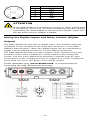
Communication Connections
10/100/1000BaseT(X) Ethernet Port Connection
The 10/100/1000BaseT(X) ports located on the AWK-4252A’s front
panel are used to connect to Ethernet-enabled devices.
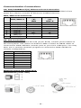
MDI/MDI-X Port Pinouts
Pin
1000BaseT
MDI/MDI-X
10/100BaseT
(X)
MDI
10/100BaseT
(X)
MDI-X
1
TRD(0)+
TX+
RX+
2
TRD(0)–
TX-
RX-
3
TRD(1)+
RX+
TX+
4
TRD(2)+
–
–
5
TRD(2)-
–
–
6
TRD(1)-
RX-
TX-
7
TRD(3)+
–
–
8
TRD(3)-
–
–
RS-232 Connection
The AWK-4252A has one RS-232 (8-pin RJ45) console port located on
the front panel. Use either an RJ45-to-DB9 or RJ45-to-DB25 cable to
connect the AWK-4252A’s console port to your PC’s COM port. You may
then use a console terminal program to access the AWK-4252A for
console configuration.
Pin
Description
1
DSR
2
NC
3
GND
4
TXD
5
RXD
6
NC
7
NC
8
DTR
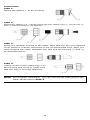
Waterproofing the RJ45 Plug
Dimensions (unit: mm)

- 13 -
Installation
STEP 1:
Attach the gasket
① to the housing ③
STEP 2:
Insert the cable (e.g., CAT5e) through the clamp ring ④, screw nut ②,
seal ⑤ and housing ③, as follows:
STEP 3:
Crimp the modular RJ plug to the cable. Note that the use of a snagless
cover shield or a strain-relief boot is not recommended here. After you
have crimped the cable, assemble the seal and the housing (③ and ⑤)
as indicated below:
STEP 4:
Tightly screw on the clamp ring
④ to
the housing and check to make sure
that the plug is securely fastened.
NOTE
For a tighter connection, you can
connect the RJ45 plug to the
AWK-4252A before STEP 4.

- 14 -
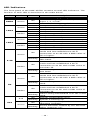
LED Indicators
The front panel of the AWK-4252A contains several LED indicators. The
function of each LED is described in the table below:
LED
Color
State
Description
Front Panel LED Indicators (System)
PWR1 Green On
Power is being supplied from power
input 1, 2, or PoE.
Off
Power is not being supplied.
LAN2
Green
On
LAN port’s 1000 Mbps link is active.
Blinking
Data is being transmitted at 1000 Mbps.
Off
LAN port’s 1000 Mbps link is inactive.
Amber
On
LAN port’s 100 Mbps link is active.
Blinking
Data is being transmitted at 100 Mbps.
Off
LAN port’s 100 Mbps link is inactive.
LAN1
Green
On
LAN port’s 1000 Mbps link is active.
Blinking
Data is being transmitted at 1000 Mbps.
Off
LAN port’s 1000 Mbps link is inactive.
Amber
On
LAN port’s 100 Mbps link is active.
Blinking
Data is being transmitted at 100 Mbps.
Off
LAN port’s 100 Mbps link is inactive.
2.4G
Green
On
Device is in Client/Client-Router/Slave
mode and has established a Wi-Fi
connection to an AP with a SNR value of
35 or higher.
Blinking Data is being transmitted over the 2.4
GHz band.
Amber
On
Device is in
Client/Client-Router/Slave
mode and
has established a Wi-Fi
connection to an AP with a SNR value of
less than 35.
Blinking
Data is being transmitted over the 2.4
GHz band.
5G
Green
On
Device is in Client/Client-Router/Slave
mode and has established a Wi-Fi
connection to an AP with a SNR value of
35 or higher.
Blinking
Data is being transmitted over the 5 GHz
band.
Amber
On
Device is in
Client/Client-Router/Slave
mode and
has established a Wi-Fi
connection to an AP with a SNR
value of
less than 35.
Blinking
Data is being transmitted over the
5
GHz
band.
SYS
Red
On
System configuration error.
Blinking
System is booting up.
Green
On
System startup
completed and is
operating normally.
Blinking
Device has been located by the Wireless
Utility (interval: 1s).

- 15 -
Specifications
Input Current
12-48 VDC, 2.2-0.5 A
Input Voltage 12 to 48 VDC, redundant dual power inputs,
48 VDC Power over Ethernet
Power Consumption
28 W (max.)
Operating Temperature Wide Temp. Models: -40 to 75°C (-40 to
167°F)
Storage Temperature
-40 to 85°C (-40 to 185°F)
NOTE
To meet the standard for IP68 protection, all unused ports
should be covered with the protective caps.
ATTENTION
The
AWK-4252A
is NOT a portable mobile device and should be
located at least 20 cm away from the human body.
The
AWK-4252A is NOT designed for the general public. To
en
sure that your AWK-4252A wireless network is safe and
configured correctly, consult a well
-trained technician to assist
with the installation process.
ATTENTION
Use the appropriate antennas for your wireless setup: Use 2.4
GHz antennas when the
AWK-4252A is configured for IEEE
802.11b/g/n. Use 5 GHz antennas when the
AWK-4252A is
configured for IEEE
802.11a/n/ac
. Make sure that the antennas
are located in an area
with a lightning and surge protection
system installed.
ATTENTION
Do not locate the antenna near overhead power lines or other
electric light or power circuits, or where it can come into
contact with such
circuits. When installing the antenna, take
extreme care not to come into contact with such circuits,
because they may cause serious injury or death. For proper
installation and grounding of the antenna, refer to national and
local co
des (for example, U.S.: NFPA 70; National Electrical
Code (NEC) Article 810;
Canada: Canadian Electrical Code,
Section 54).

- 16 -
NOTE
For installation flexibility, you can use either antenna 1 or
antenna 2
. Make sure the antenna connection matches the
antenna
s configured in the AWK-4252A web interface.
To protect the connectors and RF module, all radio ports should
be terminated by either an antenna or a terminator.
We
strongly recommend using resistive terminators for terminating
the unused antenna ports.
Software Setup
This section covers the software setup for the AWK-4252A.
How to Access the AWK
Before installing the AWK device (AWK), make sure that all items in the
package checklist are provided in the product box. You will also need
access to a notebook computer or PC equipped with an Ethernet port.
Step 1: Select a suitable power source and plug in the AWK.
The AWK can be powered by DC power ranging from 12 VDC to 48
VDC or by a PoE PSE via an Ethernet connection.
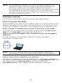
Step 2: Connect the AWK to the notebook or PC via the AWK’s
LAN port.
The LED indicator on the AWK’s LAN port will light up when a
connection is established.
NOTE
If you are using an Ethernet-to-USB adapter, follow the
instructions in the user’s manual provided with the adapter.
Step 3: Set up the computer’s IP address.
Choose an IP address for the computer that is on the same subnet as
the AWK. Since the AWK’s default IP address is 192.168.127.253, and
the subnet mask is 255.255.255.0, set the IP address to
192.168.127.xxx, where xxx is a value between 1 and 252.

- 17 -
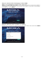
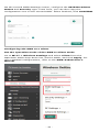
Step 4: Access the homepage of the AWK.
Open your computer’s web browser and type
https://192.168.127.253 in the address field to access the AWK’s
homepage. If successfully connected, the AWK’s interface homepage
will appear. Click NEXT.
Step 5: Choose your country or region.
Select your country or region from the drop-down list and click NEXT.

- 18 -
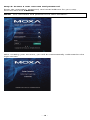
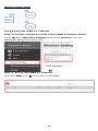
Step 6: Create a user account and password.
Enter the username, password, and email address for your user
account and click CREATE.
NOTE
The username and password are case-sensitive.
After creating your account, you will be automatically redirected to the
login screen.

- 19 -
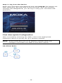
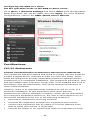
Step 7: Log in to the device.
Enter your username and password and click LOG IN. The device will
start initializing, this may take several seconds. Once the warning
message has disappeared, you can log in using your username and
password.
.
First-time Quick Configuration
After successfully accessing the AWK, refer to the appropriate
subsection below to quickly set up a wireless network.
NOTE
Ensure that there are no IP address conflicts when you
configure more than one AWK on the same subnet.
AP/Client Mode

- 20 -
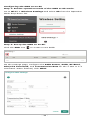
Configuring the AWK as an AP
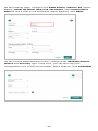
Step 1: Set the operation mode of the AWK to AP mode.
Go to Wi-Fi Wireless Settings and select AP from the Operation
Mode drop-down list.
Step 2: Set up the AWK as an AP.
Click the ADD icon to create a new SSID.
On the settings page, configure the SSID Status, SSID, RF Band,
RTS/CTS Threshold, and Transmission Rate for the 5 GHz or 2.4
GHz band. When finished, click NEXT.
La page est en cours de chargement...
La page est en cours de chargement...
La page est en cours de chargement...
La page est en cours de chargement...
La page est en cours de chargement...
La page est en cours de chargement...
-
 1
1
-
 2
2
-
 3
3
-
 4
4
-
 5
5
-
 6
6
-
 7
7
-
 8
8
-
 9
9
-
 10
10
-
 11
11
-
 12
12
-
 13
13
-
 14
14
-
 15
15
-
 16
16
-
 17
17
-
 18
18
-
 19
19
-
 20
20
-
 21
21
-
 22
22
-
 23
23
-
 24
24
-
 25
25
-
 26
26


Moxa AWK-4252A Series Read Out Instrumentation Guide d'installation
- Taper
- Guide d'installation
dans d''autres langues
Documents connexes
Autres documents
-
Solo Base Station Manuel utilisateur
-
Leonton EG5-1600-M12XB-67 Manuel utilisateur
-
Samsung AR12HSFNBWKN Manuel utilisateur
-
Samsung AR09HSFNCWKN Manuel utilisateur
-
Inovonics EN1501 Manuel utilisateur
-
Aroma AWK-115SB Manuel utilisateur
-
Samsung AR18HSFNBWKN Manuel utilisateur
-
Korg SQ-10 Le manuel du propriétaire
-
Tamiya Blackfoot III Le manuel du propriétaire
-
LG 42LX6500-CA Le manuel du propriétaire