
TC NO. 0780EF
RAF-25FX8 / RAC-25FX8
RAF-35FX8 / RAC-35FX8
SERVICE MANUAL
TECHNICAL INFORMATION
INFORMATIONS TECHNIQUES
REFER TO THE FOUNDATION MANUAL
REPORTEZ-VOUS AU MANUEL DE BASE
ROOM AIR CONDITIONER
SPECIFICATIONS AND PARTS ARE SUBJECT TO CHANGE FOR IMPROVEMENT.
LES SPECIFICATIONS ET PIECES DETACHEES PEUVENT CHANGER POUR ETRE AMELIOREES.
FOR SERVICE PERSONNEL ONLY
RESERVE AU PERSONNEL
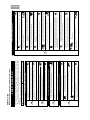
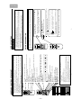
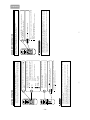
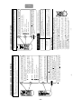
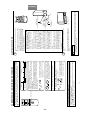
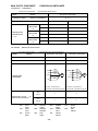
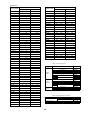
SPECIFICATIONS
CARACTERISTIQUES GENERALES
SPECIFICATIONS
CARACTERISTIQUES GENERALES
HOW TO USE
UTILISATION
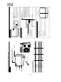
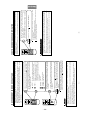
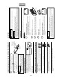
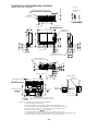
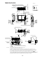
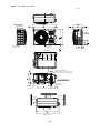
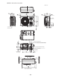
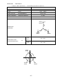
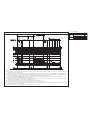
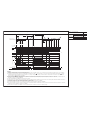
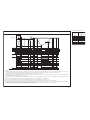
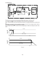
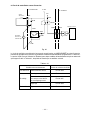
CONSTRUCTION AND DIMENSIONAL DIAGRAM
DIMENSIONS DES UNITÉS
MAIN PARTS COMPONENT
PRINCIPAUX COMPOSANTS
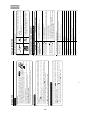
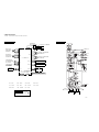
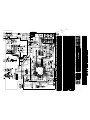
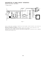
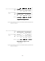
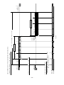
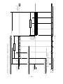
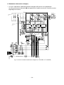
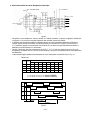
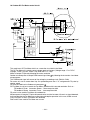
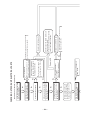
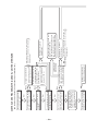
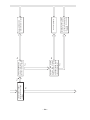
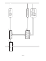
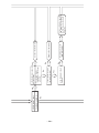
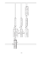
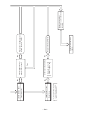
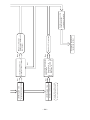
WIRING DIAGRAM
SCHÉMAS ÉLECTRIQUES
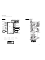
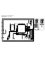
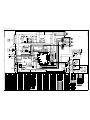
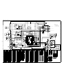
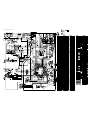
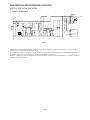
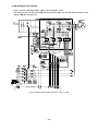
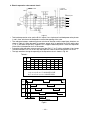
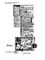
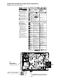
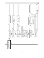
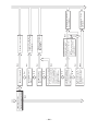
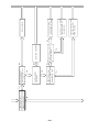
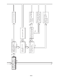
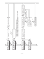
WIRING DIAGRAM OF THE PRINTED WIRING BOARD
SCHÉMA ÉLECTRIQUE DU CIRCUIT IMPRIMÉ
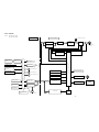
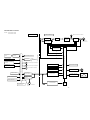
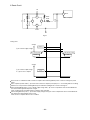
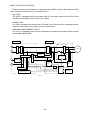
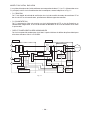
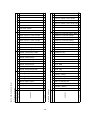
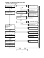
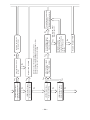
BLOCK DIAGRAM
ORGANIGRAMME DE CONTRÔLE
BASIC MODE
MODE DE BASE
REFRIGERATING CYCLE DIAGRAM
SCHÉMA DU CYCLE DE RÉFRIGÉRATION
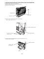
PROCEDURE D'ASSEMBLAGE ET DESASSEMBLAGE
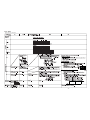
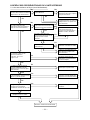
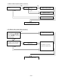
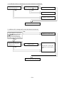
DESCRIPTION OF MAIN CIRCUIT OPERATION
DESCRIPTION DES PRINCIPAUX CIRCUITS ÉLECTRIQUES
SERVICE CALL Q&A
MODE OPERATOIRE DE DEPANNAGE
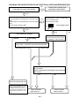
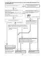
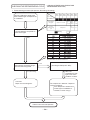
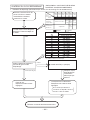
TROUBLE SHOOTING
DETECTION DES PANNES
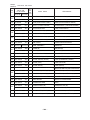
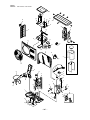
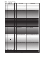
PARTS LIST AND DIAGRAM
LISTE DES PIÉCES DE RECHANGE
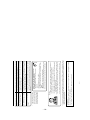
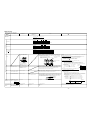
CONTENTS
TABLE DES MATIERES
INDOOR UNIT + OUTDOOR UNIT
MARCH 2008 Hitachi Appliances, Inc.
8
9
32
36
39
43
53
57
78
80
90
148
156
204
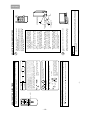
OUTDOOR UNIT
UNITÉ EXTÉRIEURE
INDOOR UNIT
UNITÉ INTÉRIEURE
After installation Après installation
750
590
215
15
750 (+91)
548
288 (+47)
35
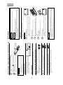
RAF-25FX8 RAC-25FX8
TYPE TYPE
MODEL MODÈLE
POWER SOURCE
PHASE/TENSION/FREQUENCE)
TOTAL INPUT
PUISSANCE ABSORBEE TOTALE (W)
TOTAL AMPERES
AMPERES TOTAUX (A)
CAPACITY CAPACITE
(kW)
(B.T.U./h)
TOTAL INPUT
PUISSANCE ABSORBEE TOTALE (W)
TOTAL AMPERES
AMPERES TOTAUX (A)
CAPACITY CAPACITE
(kW)
(B.T.U./h)
W, L
DIMENSIONS DIMENSIONS (mm) H, H
D, P
NET WEIGHT POIDS NET (kg)
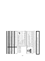
DC INVERTER INVERSEUR C.C.
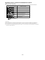
INDOOR UNIT
UNITÉ INTÉRIEURE
OUTDOOR UNIT
UNITÉ EXTÉRIEURE
580 (155 - 1,160)
2.66 - 2.55
2.5 (0.9 - 3.1)
8,533 (3,072 - 10,580)
790 (115 - 1,170)
3.63 - 3.47
3.4 (0.9 - 4.4)
11,604 (3,072 - 15,017)
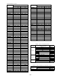
750
590
215
15
750 (+91)
548
288 (+47)
35
1,020 (155 - 1,380)
4.68 - 4.48
3.5 (0.9 - 4.0)
11,946 (3,072 - 13,652)
1,220 (115 - 1,350)
5.60 - 5.36
4.5 (0.9 - 5.0)
15,359 (3,072 - 17,065)
COOLING
RÉFRIGÉRATION
HEATING
CHAUFFAGE
RAF-25FX8
RAF-35FX8
RAC-25FX8
RAC-35FX8
RAF-35FX8 RAC-35FX8
INDOOR UNIT
UNITÉ INTÉRIEURE
OUTDOOR UNIT
UNITÉ EXTÉRIEURE
1ø, 220V - 230V, 50Hz

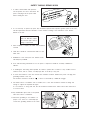
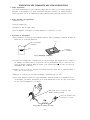
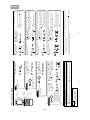
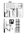
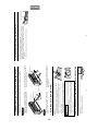
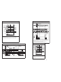
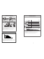
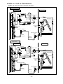
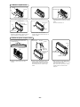
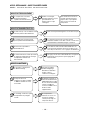
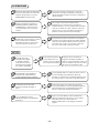
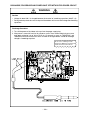
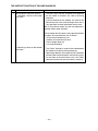
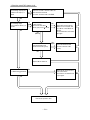
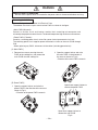
1. In order to disassemble and repair the
unit in question, be sure to disconnect the
power cord plug from the power outlet
before starting the work.
2. If it is necessary to replace any parts, they should be replaced with respective genuine parts for the unit,
and the replacement must be effected in correct manner according to the instructions in the Service
Manual of the unit.
3. After completion of repairs, the initial state should be
restored.
4. Lead wires should be connected and laid as in the
initial state.
5. Modification of the unit by the user himself should
absolutely be prohibited.
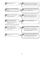
6. Tools and measuring instruments for use in repairs or inspection should be accurately calibrated in
advance.
7. In installing the unit having been repaired, be careful to prevent the occurrence of any accident such as
electrical shock, leak of current, or bodily injury due to the drop of any part.
8. To check the insulation of the unit, measure the insulation resistance between the power cord plug and
grounding terminal of the unit.
The insulation resistance should be 1M or more as measured by a 500V DC megger.
9. The initial location of installation such as window, floor or the other should be checked for being safe
enough to support the repaired unit again.
If it is found not so strong and safe, the unit should be installed at the initial location after reinforced or
at a new location.
10. Any inflammable object must not be placed
about the location of installation.
11. Check the grounding to see whether it is
proper or not, and if it is found improper,
connect the grounding terminal to the earth.
Spray
gasoline
gasbombe
thinner
SAFETY DURING REPAIR WORK
If the contacts of electrical
parts are defective, replace
the electrical parts without
trying to repair them
1
2
3
4
5

– 1 –
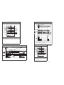
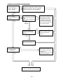
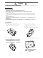
1. Avant de procéder à une réparation, veillez
à couper l'alimentation électrique.
2. Les pièces de rechange doivent être des pièces d'origine et le remplacement des pièces doit être réalisé
conformément aux instructions figurant dans le manuel d'entretien.
3. Après achèvement des réparations, les conditions
initiales doivent être rétablies.
4. Après toute intervention, le raccordement et le
cheminement des câbles électriques doivent être
rétablis comme à l'origine.
5. Toute modification au niveau de l'installation ne peut être effectuée que par une personne compétente.
Toute intervention ou modification par l'utilisateur lui-même est par conséquent à proscrire.
6. Les outils et les appareils de mesure qui doivent être employés pour effectuer l'entretien auront été
préalablement réglés ou étalonnés comme il convient.
7. Lors de l'installation d'une unité ayant subi une réparation, veillez à éviter tout accident dû à une décharge
électrique ou la chute d'un objet.
8. Pour vérifier l'isolement de l'appareillage, mesurer la résistance entre le cordon d'alimentation et la borne
de masse. Cette résistance doit au moins être égale à 1M lorsque la mesure est effectuée avec un
mégohmmètre de 500V CC.
9. Avant la fixation de l'unité réparée, vérifiez que les fixations d'origine peuvent supporter l'appareil. Si ces
fixations vous paraissent défectueuses, renforcez-les si possible et dans le cas contraire, l'unité doit être
fixée à un autre endroit.
10. L'emplacement de l'installation doit être
éloigné de toute matière inflammable.
11. La mise à la masse doit être soigneusement
contrôlée; en cas de défaut, la borne de
masse doit être mise à la terre.
Il faut d'abord que je coupe
I'alim
entation électrique.
Aérosol
Essence
Dilunt
Bonbonne de gaz
PRECAUTIONS RELATIVES A LA SECURITE PENDANT LES REPARATIONS
Si vous constatez que les contacts d'un
composant électrique sont défectueux,
remplacez le composant et ne tentez pas
de réparer les contacts.
1
2
3
4
5

– 2 –
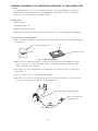
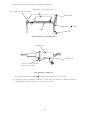
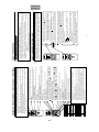
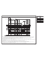
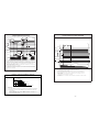
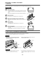
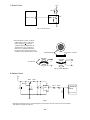
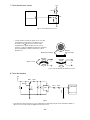
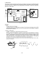
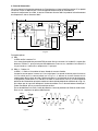
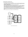
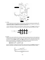
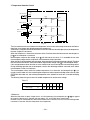
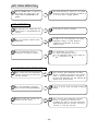
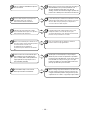
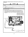
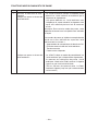
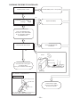
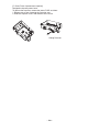
WORKING STANDARDS FOR PREVENTING BREAKAGE OF SEMICONDUCTORS
1. Scope
The standards provide for items to be generally observed in carrying and handling semiconductors in
relative manufactures during maintenance and handling thereof. (They apply the same to handling of
abnormal goods such as rejected goods being returned.)
2. Object parts
(1) Microcomputer
(2) Integrated circuits (I.C.)
(3) Field effective transistor (F.E.T.)
(4) P.C. boards or the like to which the parts mentioned in (1) and (2) of this paragraph are equipped.
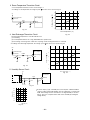
3. Items to be observed in handling
(1) Use a conductive container for carrying and storing of parts. (Even rejected goods should be handled in
the same way.)
(2) When any part is handled uncovered (in counting, packing and the like), the handling person must
always use himself as a body earth. (Make yourself a body earth by passing one M ohm earth
resistance through a ring or bracelet.)
(3) Be careful not to touch the parts with your clothing when you hold a part even if a body earth is
being taken.
(4) Be sure to place a part on a metal plate with grounding.
(5) Be careful not to fail to turn off power when you repair the printed circuit board. At the same time,
try to repair the printed circuit board on a grounded metal plate.
H
IT
A
C
H
I I
C
4
0
1
T
H
1
,
1
8
8
U
V
Fig. 1 Conductive container
A conductive polyvinyl bag
IC
IC
Conductive sponge
Fig. 2 Body earth
Body earth (Elimik conductive band)
Clip for connection with
a grounding wire
1M

– 3 –
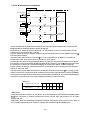
PREVENTION DES DOMMAGES AUX SEMI-CONDUCTEURS
1. Champ d'application
Pour éviter d'endommager les semi-conducteurs utilisés dans les unités, lors de chaque intervention
d'entretien ou de réparation, vous devez observer des précautions spéciales. Les mêmes précautions
doivent être prises lors de la manipulation d'organes défectueux qui doivent être retournés en usine.
2. Pièces détachées de l'appareillage.
(1) Microprocesseur
(2) Circuits intégrés (C.I.)
(3) Transistor à effet de champ (T.E.C)
(4) Circuits imprimés sur lesquels se trouvent implantés les composants (1) et (2).
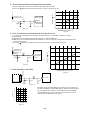
3. Précautions de manipulation
(1) Pour transporter ou stocker un semi-conducteur, placez-le dans un emballage conducteur. Procéder de
même avec un composant défectueux.
(2) Lorsque vous maniqulez des composants qui ne sont pas protégés (par exemple pour les compter ou
les emballer), vous devez veiller à ce que votre corps soit électriquement relié à la terre. Pour cela,
portez un bracelet conducteur. Reliez le bracelet à une résistance de 1M et celle-ci à la terre par
l'intermédiaire d'un conducteur.
(3) Veillez en outre à ce que vos vêtements ne viennent jamais en contact avec le composant même si
votre corps est relié à la terre.
(4) Déposez le composant sur une surface métallique correctement mise à la terre.
(5) Sous aucun prétexte, n'omettez de couper l'alimentation avant de procéder à une réparation sur un
circuit imprimé. Par ailleurs, l'intervention sur le circuit imprimé doit se faire alors que celui-ci repose
sur une surface métallique mise à la masse.
H
IT
A
C
H
I IC
4
0
1
T
H
1
,
1
8
8
U
V
Fig. 1 Emballage conducteur
Sac en polyvinyle
conducteur
C.I.
C.I.
Eponge
conductrice
Fig. 2 Mise à la terre du corps
Bracelet de mise à la terre du corps
(Bande conductrice Elimik)
Pince de connexion avec
fil de mise à la terre
1M

– 4 –
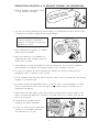
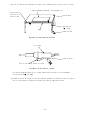
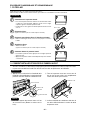
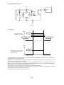
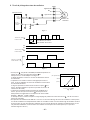
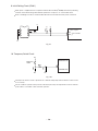
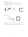
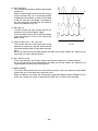
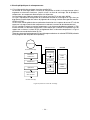
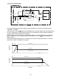
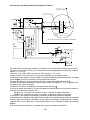
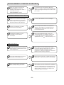
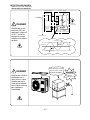
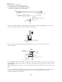
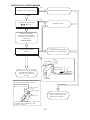
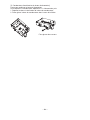
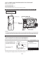
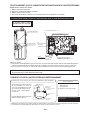
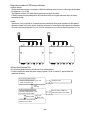
(6) Use a three wire type soldering iron including a grounding wire.
Fig.4 Grounding a solder iron
Use a high insulation mode (100V, 10M or higher) when ordinary iron is to be used.
(7) In checking circuits for maintenance, inspection, or some others, be careful not to have the test probes
of the measuring instrument shortcircuit a load circuit or the like.
Bare copper wire (for body earth)
Metal plate (of Al. stainless steel, etc.)
Working table
Resistor 1M (1/2W)
Earth wirte
Staple
Fig.3 Grounding of the working table
soldering iron
Grounding wire
Screw stop at the screwed
part using a rag plate

– 5 –
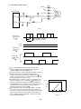
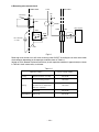
(6) Le fer à souder doit être alimenté par un câble à trois conducteurs (dont un pour la mise à la terre).
Fig.4 Mise à la terre d'un fer à souder
Vous pouvez également utiliser un fer à souder ordinaire dans la mesure où il est parfaitement
isolé (au moins 10M sous 100V).
(7) Pendant le contrôle des circuits au cours des opérations d'entretien ou d'inspection, évitez à tout prix la
mise en court-circuit de la charge par les pointes de contact de l'appareil de mesure.
Fil de cuivre nu
(pour mise à la
terre du corps)
Surface métallique (aluminium, acier inoxydable, etc.)
Plan de travail
Résistance de
1M (1/2W)
Câble de masse
Agrafe
Fig.3 Mise à la terre d'un plan de travail
fer à souder
Câble de masse
Poser ici une rondelle éventail et la visser

– 6 –
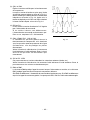
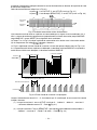
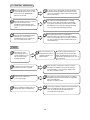
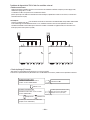
1. In quiet operation or stopping the running, its heard slight flowing noise of
refrigerant in the refrigerating cycle occasionally, but this noise is not abnormal
for the operation.
2. When it thunders near by, it is recommend to stop the operation and to
disconnect the power cord plug from the power outlet for safety.
3. The room air conditioner dose not start automaticaly after recovery of the
electric power failure for preventing fuse blowing. Re-press START / STOP
button after 3 minutes from when unit stopped.
4. If the room air conditioner is stopped by adjusting thermostat, or missoperation,
and re-start in a moment, there is occasion that the cooling and heating
operation does not start for 3 minutes, it is not abnormal and this is the result
of the operation of IC delay circuit. This IC delay circuit ensures that there is
no danger of blowing fuse or damaging parts even if operation is restarted
accidentally.
5. This room air conditioner should not be used at the cooling operation when the
outside temperature is below –10˚C (14˚F).
6. This room air conditioner (the reverse cycle) should not be used when the
outside temperature is below –15˚C (5˚F).
If the reverse cycle is used under this condition, the outside heat exchanger is
frosted and efficiency falls.
7. When the outside heat exchanger is frosted, the front is melted by operating
the hot gas system, it is not trouble that at this time fan stops and the vapour
may rise from the outside heat exchanger.
CAUTION

– 7 –
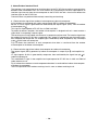
1. Dans certaines conditions et pendant un arrêt de fonctionnement, on peut
parfois entendre le bruit du réfrigérant circulant dans les canalisations; ce bruit
n'a rien d'anormal.
2. Pour des raisons de sécurité, il est conseillé, pendant un orage, d'arrêter le
fonctionnement du système en coupant l'alimentation électrique.
3. Pour éviter que le fusible ne fonde, le climatiseur ne démarre pas
automatiquement après une panne de secteur. La remise en marche suppose
une pression sur la touche START / STOP après un délai d'au moins 3 minutes
suivant l'arrêt.
4. Si le climatiseur est arrêté à la suite d'un réglage de thermostat, ou à cause
d'une fausse manoeuvre et qu'il est remis en route, il se peut que la
réfrigération ou le chauffage ne reprenne qu'après 3 minutes. Ce phénomène
est normal et dû à un relais temporisé. Ce relais temporisé a pour rôle
d'éviter que le fusible ne fonde ou que des composants ne soient
endommagés par une remise en service accidentelle.
5. Ce climatiseur ne doit pas être utilisé pour réfrigérer une pièce lorsque la
température extérieure est inférieure à –10˚C (14˚F).
6. Ce climatiseur ne doit pas être utilisé lorsque la température extérieure est
inférieure à –15˚C (5˚F).
En effet, dans ce cas, l'échangeur de chaleur extérieur gèle et le rendement
chute considérablement.
7. Quand l'échangeur de chaleur extérieur est givré, les gaz chauds peuvent
entraîner une vaporisation de l'eau accumulée sur la face avant. Ce n'est pas
un problème si à ce moment-là le ventilateur s'arrête et il se peut que de la
vapeur se dégage de l'échangeur de chaleur extérieur.
ATTENTION

– 8 –
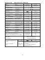
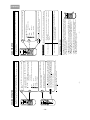
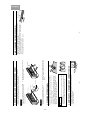
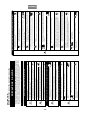
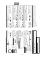
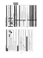
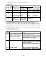
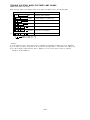
MODEL
FAN MOTOR
FAN MOTOR CAPACITOR
FAN MOTOR PROTECTOR
COMPRESSOR
OVER HEAT PROTECTOR
OVERLOAD RELAY
FUSE (for MICRO COMPUTER)
POWER RELAY, STICK RELAY
POWER SWITCH
TEMPORARY SWITCH
SERVICE SWITCH
TRANSFORMER
VARISTOR
NOISE SUPPRESSOR
THERMOSTAT
REFRIGERANT CHARGING VOLUME
(R410A)
CHARGE EN RÉFRIGÉRANT
(R410A)
UNIT UNITÉ
PIPES
CANALISATIONS
(MAX. 20m)
SPECIFICATIONS CARACTERISTIQUES GENERALES
MODÈLE
MOTEUR DE VENTILATEUR
COMPRESSEUR
RELAIS DE SURCHARGE
INTERRUPTEUR D'ALIMENTATION
INTERRUPTEUR AUXILIAIRE
INTERRUPTEUR DE SERVICE
TRANSFORMATEUR
VARISTANCE
ANTIPARASITAGE
THERMOSTAT
CONDENSATEUR DE MOTEUR
DE VENTILATEUR
PROTECTION DU MOTEUR
DE VENTILATEUR
PROTECTION CONTRE LES
SURCHAUFFES
FUSIBLE
(pour MICROPROCESSEUR)
RELAIS DE PUISSANCE,
RELAIS AUTOEXCITE
REMOTE CONTROL SWITCH (LIQUID CRYSTAL)
INTERRUPTEUR DE TÉLÉCOMMANDE (CRISTAUX LIQUIDES)
YES (RAR-3U2)
OUI (RAR-3U2)
NO
NON
FUSE CAPACITY
CALIBRE DE FUSIBLE
25W (DC35V)
NO NON
NO NON
NO NON
NO NON
YES OUI
NO NON
NO NON
NO NON
NO NON
YES (IC) OUI (IC)
40W (DC380V)
EU1011E7
YES OUI
YES OUI
3A
G4A
NO NON
YES OUI
NO NON
450NR
NO NON
NO NON
WITHOUT REFRIGERANT BECAUSE COUPLING
IS FLARE TYPE.
SANS RÉFRIGÉRANT EN RAISON DU
RACCORDEMENT FLARE.
A INRUSH - WITH STAND TYPE
A RETARDE-AVEC STAND TYPE
NO NON
NO NON
NO NON
870g
RAF-25FX8
RAF-35FX8
RAC-25FX8
RAC-35FX8

– 9 –
HOW TO USE
MODEL RAF-25FX8 / RAC-25FX8, RAF-35FX8 / RAC-35FX8
– 3 –
ENGLISH
FRANÇAIS
ITALIANO
PORTUGUÊS
œœÀ”»Œø
Do not place plants directly under the air flow as it is bad for the plants.
Do not direct the cool air coming out from the air-conditioner panel to face household
heating apparatus as this may affect the working of apparatus such as the electric
kettle, oven etc.
The product shall be operated under the manufacturer specification and not for any
other intended use.
PRECAUTIONS DURING OPERATION
CAUTION
Do not attempt to operate the unit with wet hands, this could cause fatal accident.
When operating the unit with burning equipments, regularly ventilate the
room to avoid oxygen insufficiency.
Please ensure that outdoor mounting frame is always stable, firm and without
defect. If not, the outdoor unit may collapse and cause danger.
Do not wash the unit with water or place a water container such as a vase on the
indoor unit.
Electrical leakage could be present and cause electric shock.
Be sure to stop the operation by using the remote controller and turn off the circuit
breaker during cleaning, the high-speed fan inside the unit may cause danger.
Turn off the circuit breaker if the unit is not be operated for a long period.
Do not climb on the outdoor unit or put objects on it.
When operating the unit with the door and windows opened, (the room humidity is
always above 80%) and with the air deflector facing down or moving automatically
for a long period of time, water will condense on the air deflector and drips down
occasionally. This will wet your furniture. Therefore, do not operate under such
condition for a long time.
If the amount of heat in the room is above the cooling or heating capability of the unit
(for example: more people entering the room, using heating equipments and etc.),
the preset room temperature cannot be achieved.
Indoor unit cleaning must be performed by authorized personnel only. Consult your
sales agent.
Using a commercially available detergent or similar can damage the plastic parts
or clog the drain pipe, causing water to drip with potential electric shock hazard.
Do not touch the air outlet, bottom surface and aluminum fin of the outdoor
unit.
You may get hurt.
Do not touch the refrigerant pipe and connecting valve.
Burns may result.
PROHIBITION
DON'T WET
PROHIBITION
PROHIBITION
PROHIBITION
DON’T TOUCH
"OFF"
PROHIBITION
PROHIBITION
PROHIBITION
PROHIBITION
PROHIBITION
DONíT TOUCH
"OFF"
STRICTLY OBSERVE
PRECAUTIONS
– 2 –
PRECAUTIONS DURING OPERATION
WARNING
WARNING
SAFETY PRECAUTION
Please read the “Safety Precaution” carefully before operating the unit to ensure correct usage of the unit.
Pay special attention to signs of “
Warning” and “ Caution”. The “Warning” section contains matters
which, if not observed strictly, may cause death or serious injury. The “Caution” section contains matters
which may result in serious consequences if not observed properly. Please observe all instructions strictly to
ensure safety.
The signs indicate the following meanings. (The following are examples of signs.)
Please keep this manual after reading.
Do not reconstruct the unit.
Water leakage, fault, short circuit or fire may occur if you reconstruct the unit by
yourself.
Please ask your sales agent or qualified technician for the installation of your unit.
Water leakage, short circuit or fire may occur if you install the unit by yourself.
Please use earth line.
Do not place the earth line near water or gas pipes, lightning-conductor, or the
earth line of telephone. Improper installation of earth line may cause electric
shock or fire.
Be sure to use the specified piping set for R410A. Otherwise, this may result in
broken copper pipes or faults.
A circuit breaker should be installed depending on the mounting site of the unit.
Without a circuit breaker, the danger of electric shock exists.
Do not install the unit near a location where there is flammable gas. The outdoor unit
may catch fire if flammable gas leaks around it. Piping shall be suitable supported
with a maximum spacing of 1m between the supports.
Please ensure smooth flow of water when installing the drain hose.
Make sure that a single phase 220-230V power source is used.
The use of other power sources may cause electrical components to overheat and
lead to fire.
PRECAUTIONS DURING INSTALLATION
PROHIBITION
CONNECT EARTH LINE
PROHIBITION
PROHIBITION
WARNING
CAUTION
Avoid an extended period of direct air flow for your health.
Should abnormal situation arise (like burning smell), please stop operating the unit
and remove plug from the socket. Contact your agent. Fault, short circuit or fire may
occur if you continue to operate the unit under abnormal situation.
Please contact your agent for maintenance. Improper self maintenance may cause electric shock
and fire.
Please contact your agent if you need to remove and reinstall the unit. Electric shock or fire may occur
if you remove and reinstall the unit yourself improperly.
PRECAUTIONS DURING SHIFTING OR MAINTENANCE
Do not use any conductor as fuse wire, this could cause fatal accident.
During thunder storm, disconnect the plug top and turn off the circuit breaker.
Do not put objects like thin rods into the panel of blower and suction side because
the high-speed fan inside may cause danger.
Spray cans and other combustibles should not be located within a meter of the air
outlets of both indoor and outdoor units.
As a spray can’s internal pressure can be increased by hot air, a rupture may result.
PROHIBITION
PROHIBITION
PROHIBITION
PROHIBITION
"OFF"
This sign in the figure indicates prohibition. Indicates the instructions that must be followed.
"OFF"

– 10 –
– 4 –
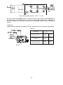
MODEL WIDTH HEIGHT DEPTH
RAF-25FX8
RAF-35FX8
750mm (29-17/32") 590mm (23-6/25") 215mm (8-15/32")
RAF-50FX8
(INDOOR UNIT)
RAC-25FX8
RAC-35FX8 750mm (29-17/32") 548mm (21-29/50") 288mm (11-17/50")
(OUTDOOR UNIT)
RAC-50FX8
792mm (31-2/13") 600mm (23-5/8") 299mm (11-19/25")
(OUTDOOR UNIT)
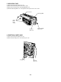
NAMES AND FUNCTIONS OF EACH PART
Remote controller
MODEL NAME AND DIMENSIONS
INDOOR UNIT
Indoor unit indicators
Horizontal air deflector (Air intake)
(Opens during operation and it closes
when it stops operation.)
Air filter
Front panel
Horizontal air
deflector (Air outlet)
Signal receiver
OUTDOOR UNIT
– 5 –
ENGLISH
FRANÇAISITALIANOSPANISH
PORTUGUÊSœœÀ”»Œø
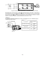
Open the front panel
•To open the front panel, use the remote controller to stop unit
operation. Then press at the top left and right corners of the front
panel.
•Grasp the left and right sides of the front panel and open it toward
you.
Close the front panel
•To close the front panel, press at the top left and right corners of the
front panel.
•Press the upper center part of the front panel to close properly.
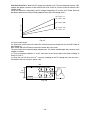
TIMER lamp
This lamp lights when the timer is working.
OPERATION lamp
This lamp lights during operation.
During heating, the operation indicator may
blink, blowing very lightly or totally stopping
under the following conditions:
(1) During preheating (heating operation)
For about 2~3 minutes after start up.
(2) During defrosting (heating operation)
Defrosting will be performed about
once an hour when frost forms on the
heat exchanger of the outdoor unit, for
5~10 minutes each time. (If the piping
length used is longer than usual, frost will
likely to form.)
TEMPORARY SWITCH
Top left and right corners
TEMPORARY SWITCH
TEMPORARY SWITCH
If the remote controller does not work due to
battery failure, press this switch to start and
stop operation.
•This temporary operation will be at the most
recent setting made. (The unit will
immediately go into automatic operation
once power is switched on.)
Upper center part
INDOOR UNIT INDICATORS
HOW TO OPEN OR CLOSE THE FRONT PANEL
FILTER lamp
This lamp lights when the
device is operated for a total
of about 200 hours, it is time
to clean the filter. The lamp
goes out when the “
(AUTO
SWING)” button is pressed
while the operation is stopped.

– 11 –
SILENT
LOW
MED
HI
AUT O
HEAT
DEHUMIDIFY
COOL
FA N
FAN SPEED
SLEEPING
STOP (CANCEL)
START (RESERVE)
START/STOP
TIME
TIMER SET
TIMER SELECTOR
ON TIMER
OFF TIMER
AUTO SWING
EXTENDED AIRFLOW
NAMES AND FUNCTIONS OF EACH PART
REMOTE CONTROLLER
This controls the operation of the indoor unit. The range of control is about 7 meters. If indoor lighting is
controlled electronically, the range of control may be shorter.
be controlled from the remote controller.
Handle the remote controller with care. Dropping it or getting it wet may compromise its signal
transmission capability.
After new batteries are inserted into the remote controller, the unit will initially require approximately 10
seconds to respond to commands and operate.
Precautions for Use
Do not put the remote controller in the following places.
In direct sunlight.
In the vicinity of a heater.
it from water.
Once the outdoor unit stops, it will not restart for about 3 minutes (unless you
turn the power switch off and on or unplug the power cord and plug it in again).
This is to protect the device and does not indicate a failure.
If you press the FUNCTION selector button during operation, the device may
stop for about 3 minutes for protection.
Signal emitting window/transmission sign
The transmission sign blinks when a signal is sent.
Display
This indicates the room temperature selected, current time, timer status, function
and intensity of circulation selected.
START/STOP button
Press this button to start operation. Press it again to stop operation.
SLEEP button
Use this button to set the sleep timer.
TEMPERATURE buttons
Use these buttons to raise or lower the temperature setting. (Keep pressed,
and the value will change more quickly.)
TIME button
Use this button to set and check the time.
RESET buttons
FUNCTION selector
Use this button to select the operating mode. Every time you press it, the mode
will change from
(AUTO) to (HEAT) to (DEHUMIDIFY) to (COOL)
and to
(FAN) cyclically.
FAN SPEED selector
This determines the fan speed. Every time you press this button, the intensity
of circulation will change from
(AUTO) to (HI) to (MED) to (LOW)
to
(SILENT). (This button allows selecting the optimal or preferred fan speed
for each operation mode.)
AUTO SWING button
EXTENDED AIRFLOW button
TIMER control
Use these buttons to set the timer.
OFF-TIMER button Select the turn OFF time.
ON-TIMER button Select the turn ON time.
RESERVE button Time setting reservation.
CANCEL button Cancel time reservation.
– 6 –
•
This unit can be fixed on a wall using the fixture provided. Before fixing it, make sure the indoor unit can
•
•
•
•
•
•
Handle the remote controller carefully
•
•
Controls the angle of the horizontal air deflector
Pushes air out further for an extended airflow
– 7 –
ENGLISH
VARIOUS FUNCTIONS
Auto Restart Control
AUTOMATIC OPERATION
The device will automatically determine the mode of operation, HEAT, COOL, or DEHUMIDIFY, depending
on the initial room temperature. The selected mode of operation will change when the room temperature
varies. However, the mode of operation will not change when indoor unit connected to multi type outdoor
unit.
Press the (FAN SPEED) button, AUTO, LOW and SILENT are available.
Press the (START/STOP) button.
Operation starts with a beep.
Press the button again to stop operation.
As the settings are stored in memory in the remote controller, you only have
to press the
(START/STOP) button next time.
You can raise or lower the temperature setting as necessary by maximum
of 3°C.
Press the temperature button and the temperature
setting will change by 1°C each time.
• The preset temperature and the actual room temperature may vary
somewhat depending on conditions.
1
START
STOP
Press the FUNCTION selector so that the display indicates the
(AUTO) mode of operation.
•When AUTO has been selected, the device will automatically
determine the mode of operation, HEAT, COOL, or DEHUMIDIFY,
depending on the current room temperature.
• If there is a power failure, operation will be automatically restarted when the power is resumed with
previous operation mode and airflow direction.
(As the operation is not stopped by remote controller.)
• If you intend not to continue the operation when the power is resumed, switch off the power supply.
When you switch on the circuit breaker, the operation will be automatically restarted with previous
operation mode and airflow direction.
Note: 1. If you do not require Auto Restart Control, please consult your sales agent.
2. Auto Restart Control is not available when Timer or Sleep Timer mode is set.

– 12 –
Set the desired FAN SPEED with the (FAN SPEED) button (the
display indicates the setting).
(AUTO) : The fan speed changes automatically according
to the temperature of the air which blows out.
(HI) : Economical as the room will become warm
quickly.
But you may feel a chill at the beginning.
(MED) : Quiet.
(LOW) : More quiet.
(SILENT) : Ultra quiet.
HEATING OPERATION
Use the device for heating when the outdoor temperature is under 21
°
C.
When it is too warm (over 21
°
C), the heating function may not work in order to protect the device.
In order to keep reliability of the device, please use this device above -15
°
C of the outdoor temperature.
Press the FUNCTION selector so that the display indicates
(HEAT).
As the settings are stored in memory in the remote controller, you only have
to press the
(START/STOP) button next time.
Set the desired room temperature with the TEMPERATURE buttons
(the display indicates the setting).
The temperature setting and the actual room temperature may vary
somewhat depending on conditions.
Press the (START/STOP) button. Heating operation starts with
a beep. Press the button again to stop operation.
1
3
2
START
STOP
Defrosting
Defrosting will be performed about once an hour when frost forms on the heat exchange of the outdoor unit,
for 5~10 minutes each time.
During defrosting operation, the operation lamp blinks in cycle of 3 seconds on and 0.5 second off.
The maximum time for defrosting is 20 minutes.
However, if it is connected to multi type outdoor unit, the maximum time for defrosting is 15 minutes.
(If the piping length used is longer than usual, frost will likely to form.)
– 8 – – 9 –
•
•
ENGLISH
DEHUMIDIFYING OPERATION
When you want to change the operation mode, please use the FUNCTION
selector.
Set the desired temperature is available.
You also can use the FUNCTION selector to select this operation.
Press the FUNCTION selector so that the display indicates
(DEHUMIDIFY).
The FAN SPEED button, LOW and SILENT.
Press the (START/STOP) button.
1
Dehumidifying takes place with a target temperature which is slightly lower than the room temperature
setting. (However, target temperature is 16°C for a temperature setting of 16°C.)
If the room temperature becomes lower than the target value, operation stops. If the room temperature
becomes higher than the target value, operation restarts.
The preset room temperature may not be reached depending on the number of people present in the room
or other room conditions.
Dehumidifying Function
START
STOP
Use the device for dehumidifying when the room temperature is over 16
°
C.
When it is under 15
°
C, the dehumidifying function will not work.
•
•

– 13 –
Set the desired FAN SPEED with the (FAN SPEED) button (the
display indicates the setting).
(AUTO) : The FAN SPEED is HI at first and varies to MED
automatically when the preset temperature has
been reached.
(HI) : Economical as the room will become cool quickly.
(MED) : Quiet.
(LOW) : More quiet.
(SILENT) : Ultra quiet.
Press the FUNCTION selector so that the display indicates
(COOL).
As the settings are stored in memory in the remote controller, you only have
to press the
(START/STOP) button next time.
Set the desired room temperature with the TEMPERATURE buttons
(the display indicates the setting).
The temperature setting and the actual room temperature may vary
somewhat depending on conditions.
Press the (START/STOP) button. Cooling operation starts with
a beep. Press the button again to stop operation. The cooling function
does not start if the temperature setting is higher than the current
room temperature (even though the
(OPERATION) lamp lights).
The cooling function will start as soon as you set the temperature
below the current room temperature.
COOLING OPERATION
1
2
3
START
STOP
– 10 – – 11 –
Use the device for cooling when the outdoor temperature is –10~42°C.
If humidity is very high (over 80%) indoors, some dew may form on the air outlet grille of the indoor unit.
ENGLISH
FAN OPERATION
You can use the device simply as an air circulator. Use this function to dry the interior of the indoor unit
at the end of summer.
FAN SPEED (AUTO)
For the cooling operation
For the heating operation
The fan speed will automatically change according to the temperature of
discharged air.
As room temperature reaches the preset temperature, a very light breeze
will blow.
Operation starts in the ìHIî mode to reach the preset temperature.
As room temperature approaches the preset temperature, fan speed
automatically switches to ìMEDî.
Press the (START/STOP) button. Fan operation starts with a
beep. Press the button again to stop operation.
Press the (FAN SPEED) button.
(HI) : The strongest air blow.
(MED) : Quiet.
(LOW) : More quiet.
(SILENT) : Ultra quiet.
Press the FUNCTION selector so that the display indicates (FAN).
1
2
START
STOP
When the (EXTENDED AIRFLOW) button is pressed during operation, the airflow
direction will automatically set according to the type of operation and the fan speed will
change to allow air to blow further. (During cooling operation, fan speed will return to
the original position after 3 hours.)
If the (EXTENDED AIRFLOW) button is pressed while the AUTO SWING mode is
set, the AUTO SWING mode is cancelled and the EXTENDED AIRFLOW mode is set.
If the
(AUTO SWING) button is pressed while the EXTENDED AIRFLOW mode is set,
the EXTENDED AIRFLOW mode is cancelled and the AUTO SWING mode is set.
Press (EXTENDED AIRFLOW) button to lower the room temperature quickly when
the temperature is high during the cooling operation.
EXTENDED AIRFLOW
•
•
•
•
•
•
•
•
If the (EXTENDED AIRFLOW) button is pressed when the horizontal air deflector
stops at your preferred angle, the deflector will change to EXTENDED AIRFLOW.
… When the AUTO fan speed mode is set in the cooling/heating operation:

– 14 –
– 12 –
Stop
Start
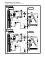
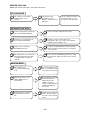
HOW TO SET THE TIMER
TIME
(current time)
OFF TIMER
ON TIMER
RESERVE
CANCEL
1
Set the (TIME) button.
1
Press the (OFF-TIMER)
button. The
(OFF) mark blinks on
the display.
After you change the
batteries;
You can set the device to turn off at
the present time.
1
Press the (ON-TIMER)
button. The
(ON) mark blinks on
the display.
The device will turn on at the
designated times.
1
Press the
(ON-OFF) button so
that the
(OFF)
mark blinks.
2
Set the turn-off time with
the TIMER control button.
Press the
(RESERVE)
button.
3
Press the (ON-
TIMER) button so that the
(OFF) mark lights and
the
(ON) mark blinks.
• The device will turn on (off) and
off (on) at the designated times.
• The switching occurs first at the
preset time that comes earlier.
• The arrow mark appearing on the
display indicates the sequence of
switching operations.
How to Cancel Reservation
Point the signal window of the remote controller toward the indoor unit, and press the (CANCEL)
button.
The
(RESERVED) sign goes out with a beep and the (TIMER) lamp turns off on the indoor unit.
NOTE
You can set only one of the OFF-timer,
ON-timer and ON/OFF-timer.
Start
Stop
AM
PM
AM
AM
PM
PM
AM
PM
StopStart
ON-Timer
OFF-Timer
Time
ON/OFF-Timer
ENGLISH
3
Point the signal window of the remote controller toward the indoor unit, and
press the (RESERVE) button.
The
(RESERVED)
sign lights. A beep occurs and the
(TIMER) lamp lights on the indoor unit.
2
Set the turn-on time with the
TIMER control button.
Example:
The device will automatically turn on earlier so that
the preset temperature can be reached at 7:00a.m.
The setting of the turn-on time is now complete.
4
Set the turn-on time with the
TIMER control button.
Example:
The device will turn off at 10:30p.m. and then
automatically turn on earlier so that the preset
temperature can be reached at 7:00a.m.
The settings of the turn-on/off times are now
complete.
5
Point the signal window of the remote controller toward the indoor unit, and
press the
(RESERVE) button.
The
(RESERVED) sign
lights. A beep occurs and the
(TIMER) lamp lights on the indoor unit.
The timer may be used in three ways: off-timer, on-timer and ON/OFF (OFF/ON)-timer. Set the current time
As the time settings are stored in memory in the remote controller, you only have to press the
(RESERVE)
button is order to use the same settings next time.
Example: The current time is 1:30p.m.
The time indication will disappear automatically in
10 seconds.
To check the current time setting, press the
(TIME)
button twice.
The setting of the current time is now complete.
2
Set the current time with
the TIMER control button.
3
Press the (TIME) button
again. The time indication starts
2
Set the turn-off time with the
TIMER control button.
3
Point the signal window of the remote controller toward the indoor unit, and
press the (RESERVE) button.
The
(RESERVED)
sign lights. A beep occurs and the
(TIMER) lamp lights on the indoor unit.
PM
PM
PM
PM
AM
AM
AM
PM
AM
PM
AM
PM
AM
PM
– 13 –
(ON) mark starts lighting instead of flashing and the
(ON) mark starts lighting instead of flashing and the
at first because it serves as a reference.
(OFF) mark starts lighting instead of flashing and the
Example:
The device will turn off at 11:00p.m.
The setting of turn-off time is now complete.
•
•
•
•
lighting instead of flashing.

– 15 –
– 14 –
HOW TO SET THE SLEEP TIMER
Set the current time at first if it is not set before (see the pages for setting the current time). Press the
(SLEEP) button and the display changes as shown below.
SLEEP
How to Cancel Reservation
Point the signal window of the remote controller toward the indoor unit, and press the (CANCEL)
button.
The
(RESERVED) sign goes out with a beep and the (TIMER) lamp turns off on the indoor unit.
Mode Indication
Sleep Timer
Sleep Timer: The device will continue working for the desired number
of hours and then turn off.
Point the signal window of the remote controller toward the indoor unit,
and press the SLEEP button.
The timer information will be displayed on the remote controller. The
TIMER lamp lights with a beep from the indoor unit. When the sleep
timer has been set, the display indicates the turn-off time.
Example: If you set 3 hours sleep time
at 11:38 p.m., the turn-off time is
2:38 a.m..
Start
Sleep
timer
The device will be turned off by the sleep timer
and turned on by on-timer.
1
Set the ON-timer.
2
Press the (SLEEP) button and set the sleep timer.
For heating:
In this case, the device will turn off in 2
hours (at 1:38 a.m.) and will turn on
early so that the present temperature
will be almost reached at 6:00 a.m. next
morning.
1 hour 2 hours 3 hours 7 hours
Sleep timer off
H
AM
H
AM
AM
– 15 –
ENGLISH
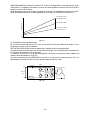
Vertical air deflector
ADJUSTING THE AIR DEFLECTORS
Adjustment of the conditioned air in the upward
and downward directions.
The horizontal air deflector is automatically set to
the proper angle suitable for each operation. The
deflector can be swung up and down continuously
and also set to the desired angle using the “
(AUTO SWING)” button.
1
CAUTION
•When operating the unit in cooling operation with the air deflector facing down and moving automatically
for a long period of time, water will be condensed on the air deflector and drips down occasionally. This
will wet your furniture.
Vertical
When
heating,
about 20°
When cooling,
dehumidifying
about 50°
about
70°
EXTENDED AIRFLOW
(Heating)
Adjustment of the conditioned air to the left and
right.
Hold the vertical air deflector as shown in the figure
and adjust the conditioned air to the left and right.
2
• If the “ (AUTO SWING)” button is
pressed once, the horizontal air deflector
swings up and down. If the button is
pressed again, the deflector stops in its
current position.
• Use the horizontal air deflector within
the adjusting range shown in the right
figure.
• When the “
(AUTO SWING)” button is
pressed while the operation is stopped,
the horizontal air deflector moves and
stops at the position where the air outlet
closes.
• When the auto swing operation is
performed, if the horizontal air deflector
is moved manually, the swinging range
may drift. However, it will return to the
original operation range after a short
time.
• When the humid in the room is high
during cooling or dehumidifying
operation, the horizontal air deflector
may automatically change to the
straight direction to prevent dew (except
during auto swing operation).
EXTENDED AIRFLOW
(Cooling, dehumidifying)

– 16 –
– 16 –
HOW TO CHANGE THE BATTERIES IN THE REMOTE CONTROLLER
CIRCUIT BREAKER
When you do not use the room air conditioner, set the circuit breaker to “OFF”.
HOW TO USE THE AIR CONDITIONER EFFECTIVELY
1. An average room temperature setting is probably the best for you as well as being
economical.
•Excessive cooling or heating is not recommended for health reasons. High electricity
bills may also result.
•Close the curtains or blinds to prevent heat from flowing into or escaping the room as
well as to make more effective use of electricity.
2. At intervals, the doors and windows should be opened to let fresh air in.
CAUTION
Make sure the room is ventilated when operating the air conditioner
at the same time as other heating appliances.
3. Using the timer is recommended before going to sleep or going out.
4. The following must never be used for cleaning the indoor and outdoor units:
•Benzine, thinner and scrub can damage plastic surfaces or coating.
•Hot water above 40°C can shrink the filter and deform plastic parts.
5. Do not block the air intake and air outlet.
•Do not block the air outlets and intakes of the indoor and outdoor units with curtains
or other obstacles which could degrade air conditioner performance and cause unit
failure.
TEMPORARY SWITCH
If the remote controller does not work due to battery failure,
press this switch to start and stop operation.
• This temporary operation will be at the setting made most
recently. (The unit will immediately go into automatic
operation once power is switched on.)
TEMPORARY SWITCH
CAUTION
1. Do not mix new and old batteries, or different type of
batteries together.
2. Remove the batteries when you do not use the remote
controller for 2 or 3 months.
Install the new batteries.
The direction of the batteries should match the marks in
the case.
Remove the cover as shown in the figure and remove the
old batteries.
2
1
Push and pull to
the direction of
arrow mark
.
Cover
– 17 –
ENGLISH
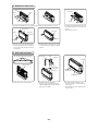
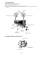
1. AIR FILTER
Clean the air filter, as it removes dust inside the room.
Be sure to clean the filter once every two weeks so as not to consume electricity unnecessarily.
PROCEDURE
MAINTENANCE
Open the front panel.
• To open the front panel, use the remote controller to stop unit
operation. Then press at the top left and right corners of the front
panel.
•Grasp the left and right sides of the front panel and open it toward you.
1
WARNING
•Before cleaning, stop unit operation with the remote controller and turn off the circuit breaker.
Remove the filters.
(Front side 2 pieces, upper side 2 pieces, total 4 pieces.)
2
Remove dust of the filters using a vacuum cleaner.
•After using neutral detergent, wash with clean water and dry in
shade.
3
Attach the filters.
•Attaching the filters.
(Front side 2 pieces, upper side 2 pieces, total 4 pieces.)
4
CAUTION
•Do not wash with hot water at more than 40°C. The filter may shrink.
•When washing it, shake off moisture completely and dry it in the shade; do not expose it directly to the sun.
The filter may shrink. And also use a soft sponge to wash. Using a scrubber or brush cause the metal film
on the surface to come off.
•Don’t operate the unit without filter. Fault may occur if you continue.
Close the front panel.
• To close the front panel, press at the top left and right corners of the
front panel.
•Press the upper center part of the front panel to close properly.
5
CAUTION
•
Do not expose the unit to water as it may cause an electric shock.
•For cleaning inside the air conditioner, consult your sales agent.
•Avoid using detergent when cleaning the heat exchanger of the indoor unit. Unit failure may result.
•When cleaning the heat exchanger with a vacuum cleaner, make sure to wear gloves so as not to injure your
hands on the heat exchanger fins.
Upper side filter
Front side filter

– 17 –
– 18 –
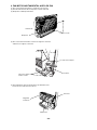
Removing
1 Press the hook found at the tip of the resin band
installed inside the front panelís right section to
remove the resin band.
2. HOW TO INSTALL AND REMOVE THE FRONT PANEL
• Be sure to use both hands to grasp the front panel when removing it or attaching it.
• The front panel may be installed up or down to suit user preference.
4. MAINTENANCE AT BEGINNING OF LONG OFF PERIOD
• Activating air conditioner drying will keep the interior of the indoor unit
dry and prevent mold formation.
•
Turn off the circuit breaker.
2 Pull the front panel down toward you and once
fully open, pull it to remove.
1 Attach three front panel bearings to the axis of
the front cover. (Set the hook to face up.)
2 Insert the tip of the resin band into the hole of the
protrusion inside the right section of the front
panel.
3. CLEANING OF FRONT PANEL
The front panel can be washed in water. It can be kept clean at all times.
•Front panel can be removed and washed in water. Gently clean the
front panel using a soft sponge.
• When the air conditioner is to be cleaned without removing the front
panel, clean both the body and remote controller with a dry soft cloth.
• Wipe off water completely. If water remains on the display section or
light receiver section, this could cause a malfunction.
CAUTION
• Do not splash or direct water to the body of the unit when cleaning it as this may
cause short circuit.
• Never clean with hot water (above 40
°C
), benzine, gasoline, acid, thinner or a
brush, because it will damage the plastic surface and the coating.
Resin band
Air blow
B
E
N
Z
I
N
E
T
H
I
N
N
E
R
A
C
I
D
Hook
Front cover
Front panel
Resin band
Attaching
– 19 –
ENGLISH
5. AIR CLEANSING FILTERS (SPX-CFH15)
• When installing the air cleansing filters, remove the air filters and attach
them onto the hooks of the front cover frame.
• The cooling capacity is slightly weakened and the cooling speed becomes
slower when the air cleansing filters are used. So, set the fan speed to
“HIGH” when using it in this condition.
• The air cleansing filters can be used for 2 years.
Air cleansing filters

– 18 –
– 20 –
Heating Capability
•
This room air conditioner utilizes a heat pump system that absorbs
exterior heat and brings it into a room to be heated. As the ambient
temperature gets lower, heating capability will also lower. In such a
situation, the PAM and inverter work to increase compressor rpm to keep
the unitís heating capability from decreasing. If the unitís heating
performance is still unsatisfactory, other heating appliances should be
used to augment this unitís performance.
•
The air conditioner is designed to heat an entire room so that it may take some time before you feel warm. Timer
Cooling and Dehumidifying Capabilities
•
If the heat present in a room exceeds the unitís cooling capacity (for example, if there are many people in the room
or other heating appliances are used), the preset room temperature may not be reached.
INFORMATION
CAPABILITIES
CAUTION
Do not use a stove
or any other high-
temperature devices
in proximity to the
indoor unit.
• When fan speed, room temperature are set with the remote controller before starting manual operation and
the buttons are released, the indication of settings will go off in 10 seconds and only the operation mode will
be displayed.
• Pressing the button while the unit is in operation will let the protective circuit work so that the unit will
not operate for approximately 3 minutes.
•
•
If you feel cold wind during warming operation with the (HI) fan speed or want to make the unit operation
quieter after the room is heated, use of
(AUTO) setting is recommended.
• With the (SILENT) setting, the unitís cooling capability will lower slightly.
VARIOUS FUNCTIONS
• When the timer has been programmed, the unit will not operate even if the set time is reached unless the unit
receives a signal from the remote controller.
that timer programming is complete (beep) and the
TIMER lamp of the indoor unit lights.
• If the (SLEEP) button is pressed while the ON/OFF timer is programmed, the sleep timer takes priority.
• During sleep timer operation, the fan speed sets to (SILENT) regardless of the preset speed. The remote
controller display indication will remain unchanged even with the
(SILENT) setting.
TIMER PROGRAMMING/SLEEP TIMER OPERATION
PROHIBITION
operation is recommended for effective preheating ahead of the desired time.
During heating operation, the indoor unit’s color indicator lamp may flash with no air emitted for a while.
– 21 –
ENGLISH
REGULAR INSPECTION
PLEASE CHECK THE FOLLOWING POINTS EVERY EITHER HALF YEARLY OR YEARLY. CONTACT YOUR
SALES AGENT SHOULD YOU NEED ANY HELP.
1
2
Check to see if the unit’s earth line has been connected
correctly.
If the earth line is disconnected or faulty, unit failure or electric
shock hazard may result.
Check to see if the mounting frame has rusted excessively
or if the outdoor unit has tilted or become unstable.
It could collapse or fall, causing injury.
WHEN ASKING FOR SERVICE, CHECK THE FOLLOWING
CONDITION CHECK THE FOLLOWING POINTS
• Do the batteries need replacement?
•Is the polarity of the inserted batteries correct?
•Is the air filter blocked with dust?
•Is the set temperature suitable?
• Have the top and bottom air deflectors been adjusted to their correct
positions according to the operation mode selected?
•Are the air inlets or air outlets of indoor and outdoor units blocked?
•Is the fan speed “LOW” or “SILENT”?
WARNING
WARNING
AFTER SALES SERVICE AND WARRANTY
•Is the fuse all right?
•Is the voltage extremely high or low?
•Is the circuit breaker “ON”?
•Is the setting of operation mode different from other indoor units?
When it does not operate.
When it does not cool well.
When it does not heat well.
<Operation start>
The unit is preparing to blow warm air. Please wait.
<In operation>
The outdoor unit is defrosting. Please wait.
Hissing or fizzy sounds
Refrigerant flow noise in the pipe or valve sound generated when flow rate is
adjusted.
Squeaking noise
Noise generated when the unit expands or contracts due to temperature
changes.
Rustling noise
Noise generated with the indoor unit fan’s rpm changing such as operation start
times.
Clicking noise Noise of the motorized valve when the unit is switched on.
Perking noise
Noise of the ventilation fan sucking in air present in the drain hose and blowing out
dehumidifying water that had accumulated in the condensed water collector. For
details, consult your sales agent.
Changing operation noise
Operation noise changes due to power variations according to room temperature
changes.
Mist emission Mist is generated as the air within the room is suddenly cooled by conditioned air.
During heating, the operation indicator
blinks and air blow stops
If the remote controller is not
transmitting a signal.
(Remote controller display is
dim or blank.)
The following phenomena do not indicate unit failure.
La page est en cours de chargement...
La page est en cours de chargement...
La page est en cours de chargement...
La page est en cours de chargement...
La page est en cours de chargement...
La page est en cours de chargement...
La page est en cours de chargement...
La page est en cours de chargement...
La page est en cours de chargement...
La page est en cours de chargement...
La page est en cours de chargement...
La page est en cours de chargement...
La page est en cours de chargement...
La page est en cours de chargement...
La page est en cours de chargement...
La page est en cours de chargement...
La page est en cours de chargement...
La page est en cours de chargement...
La page est en cours de chargement...
La page est en cours de chargement...
La page est en cours de chargement...
La page est en cours de chargement...
La page est en cours de chargement...
La page est en cours de chargement...
La page est en cours de chargement...
La page est en cours de chargement...
La page est en cours de chargement...
La page est en cours de chargement...
La page est en cours de chargement...
La page est en cours de chargement...
La page est en cours de chargement...
La page est en cours de chargement...
La page est en cours de chargement...
La page est en cours de chargement...
La page est en cours de chargement...
La page est en cours de chargement...
La page est en cours de chargement...
La page est en cours de chargement...
La page est en cours de chargement...
La page est en cours de chargement...
La page est en cours de chargement...
La page est en cours de chargement...
La page est en cours de chargement...
La page est en cours de chargement...
La page est en cours de chargement...
La page est en cours de chargement...
La page est en cours de chargement...
La page est en cours de chargement...
La page est en cours de chargement...
La page est en cours de chargement...
La page est en cours de chargement...
La page est en cours de chargement...
La page est en cours de chargement...
La page est en cours de chargement...
La page est en cours de chargement...
La page est en cours de chargement...
La page est en cours de chargement...
La page est en cours de chargement...
La page est en cours de chargement...
La page est en cours de chargement...
La page est en cours de chargement...
La page est en cours de chargement...
La page est en cours de chargement...
La page est en cours de chargement...
La page est en cours de chargement...
La page est en cours de chargement...
La page est en cours de chargement...
La page est en cours de chargement...
La page est en cours de chargement...
La page est en cours de chargement...
La page est en cours de chargement...
La page est en cours de chargement...
La page est en cours de chargement...
La page est en cours de chargement...
La page est en cours de chargement...
La page est en cours de chargement...
La page est en cours de chargement...
La page est en cours de chargement...
La page est en cours de chargement...
La page est en cours de chargement...
La page est en cours de chargement...
La page est en cours de chargement...
La page est en cours de chargement...
La page est en cours de chargement...
La page est en cours de chargement...
La page est en cours de chargement...
La page est en cours de chargement...
La page est en cours de chargement...
La page est en cours de chargement...
La page est en cours de chargement...
La page est en cours de chargement...
La page est en cours de chargement...
La page est en cours de chargement...
La page est en cours de chargement...
La page est en cours de chargement...
La page est en cours de chargement...
La page est en cours de chargement...
La page est en cours de chargement...
La page est en cours de chargement...
La page est en cours de chargement...
La page est en cours de chargement...
La page est en cours de chargement...
La page est en cours de chargement...
La page est en cours de chargement...
La page est en cours de chargement...
La page est en cours de chargement...
La page est en cours de chargement...
La page est en cours de chargement...
La page est en cours de chargement...
La page est en cours de chargement...
La page est en cours de chargement...
La page est en cours de chargement...
La page est en cours de chargement...
La page est en cours de chargement...
La page est en cours de chargement...
La page est en cours de chargement...
La page est en cours de chargement...
La page est en cours de chargement...
La page est en cours de chargement...
La page est en cours de chargement...
La page est en cours de chargement...
La page est en cours de chargement...
La page est en cours de chargement...
La page est en cours de chargement...
La page est en cours de chargement...
La page est en cours de chargement...
La page est en cours de chargement...
La page est en cours de chargement...
La page est en cours de chargement...
La page est en cours de chargement...
La page est en cours de chargement...
La page est en cours de chargement...
La page est en cours de chargement...
La page est en cours de chargement...
La page est en cours de chargement...
La page est en cours de chargement...
La page est en cours de chargement...
La page est en cours de chargement...
La page est en cours de chargement...
La page est en cours de chargement...
La page est en cours de chargement...
La page est en cours de chargement...
La page est en cours de chargement...
La page est en cours de chargement...
La page est en cours de chargement...
La page est en cours de chargement...
La page est en cours de chargement...
La page est en cours de chargement...
La page est en cours de chargement...
La page est en cours de chargement...
La page est en cours de chargement...
La page est en cours de chargement...
La page est en cours de chargement...
La page est en cours de chargement...
La page est en cours de chargement...
La page est en cours de chargement...
La page est en cours de chargement...
La page est en cours de chargement...
La page est en cours de chargement...
La page est en cours de chargement...
La page est en cours de chargement...
La page est en cours de chargement...
La page est en cours de chargement...
La page est en cours de chargement...
La page est en cours de chargement...
La page est en cours de chargement...
La page est en cours de chargement...
La page est en cours de chargement...
La page est en cours de chargement...
La page est en cours de chargement...
La page est en cours de chargement...
-
 1
1
-
 2
2
-
 3
3
-
 4
4
-
 5
5
-
 6
6
-
 7
7
-
 8
8
-
 9
9
-
 10
10
-
 11
11
-
 12
12
-
 13
13
-
 14
14
-
 15
15
-
 16
16
-
 17
17
-
 18
18
-
 19
19
-
 20
20
-
 21
21
-
 22
22
-
 23
23
-
 24
24
-
 25
25
-
 26
26
-
 27
27
-
 28
28
-
 29
29
-
 30
30
-
 31
31
-
 32
32
-
 33
33
-
 34
34
-
 35
35
-
 36
36
-
 37
37
-
 38
38
-
 39
39
-
 40
40
-
 41
41
-
 42
42
-
 43
43
-
 44
44
-
 45
45
-
 46
46
-
 47
47
-
 48
48
-
 49
49
-
 50
50
-
 51
51
-
 52
52
-
 53
53
-
 54
54
-
 55
55
-
 56
56
-
 57
57
-
 58
58
-
 59
59
-
 60
60
-
 61
61
-
 62
62
-
 63
63
-
 64
64
-
 65
65
-
 66
66
-
 67
67
-
 68
68
-
 69
69
-
 70
70
-
 71
71
-
 72
72
-
 73
73
-
 74
74
-
 75
75
-
 76
76
-
 77
77
-
 78
78
-
 79
79
-
 80
80
-
 81
81
-
 82
82
-
 83
83
-
 84
84
-
 85
85
-
 86
86
-
 87
87
-
 88
88
-
 89
89
-
 90
90
-
 91
91
-
 92
92
-
 93
93
-
 94
94
-
 95
95
-
 96
96
-
 97
97
-
 98
98
-
 99
99
-
 100
100
-
 101
101
-
 102
102
-
 103
103
-
 104
104
-
 105
105
-
 106
106
-
 107
107
-
 108
108
-
 109
109
-
 110
110
-
 111
111
-
 112
112
-
 113
113
-
 114
114
-
 115
115
-
 116
116
-
 117
117
-
 118
118
-
 119
119
-
 120
120
-
 121
121
-
 122
122
-
 123
123
-
 124
124
-
 125
125
-
 126
126
-
 127
127
-
 128
128
-
 129
129
-
 130
130
-
 131
131
-
 132
132
-
 133
133
-
 134
134
-
 135
135
-
 136
136
-
 137
137
-
 138
138
-
 139
139
-
 140
140
-
 141
141
-
 142
142
-
 143
143
-
 144
144
-
 145
145
-
 146
146
-
 147
147
-
 148
148
-
 149
149
-
 150
150
-
 151
151
-
 152
152
-
 153
153
-
 154
154
-
 155
155
-
 156
156
-
 157
157
-
 158
158
-
 159
159
-
 160
160
-
 161
161
-
 162
162
-
 163
163
-
 164
164
-
 165
165
-
 166
166
-
 167
167
-
 168
168
-
 169
169
-
 170
170
-
 171
171
-
 172
172
-
 173
173
-
 174
174
-
 175
175
-
 176
176
-
 177
177
-
 178
178
-
 179
179
-
 180
180
-
 181
181
-
 182
182
-
 183
183
-
 184
184
-
 185
185
-
 186
186
-
 187
187
-
 188
188
-
 189
189
-
 190
190
-
 191
191


Hitachi RAC-25FX8 Manuel utilisateur
- Catégorie
- Climatiseurs split-system
- Taper
- Manuel utilisateur
dans d''autres langues
- English: Hitachi RAC-25FX8 User manual
Documents connexes
-
Hitachi RAF-50RXB Manuel utilisateur
-
Hitachi RAK-50NH5 Manuel utilisateur
-
-
-
-
-
-
Hitachi RAD-50NH7A Manuel utilisateur
-
Hitachi RAC-E14HB Mode d'emploi
-