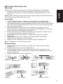
Anspach CRANI-A-G1 Assembly And Disassembly
- Taper
- Assembly And Disassembly

English
G1 High Speed Attachments
Assembly and Disassembly


English
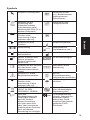
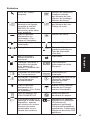
Contents
General Information ..........................................................2
Straight Attachments ........................................................7
Craniotome Attachments ..................................................8
QD Angle Attachments .....................................................9
Minimal Access Attachment and
Bearing Sleeves .............................................................10
Perforator Driver Attachment ..........................................12

2
English
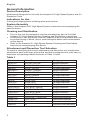
General Information
Device Description
Attachments designed for use with the Anspach G1 High Speed System and G1
Dissection Tools.
Indications for Use
Cutting and shaping bone including spine and cranium.
System Assembly
Refer to the Anspach eG1 High Speed System instructions accompanying the
specic device.
Cleaning and Sterilization
• Prior to rst use the equipment must be processed as per the included
Anspach G1 High Speed System Cleaning and Sterilization instructions.
• At the point of use the device must be cleaned as soon as possible after use
to prevent drying of blood, tissue, other biological debris and contaminants
on the device.
• Refer to the Anspach G1 High Speed System Cleaning and Sterilization
instructions accompanying this device.
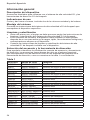
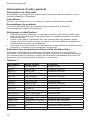
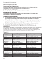
Attachment and Dissection Tool Selection
To assist in identifying the correct attachment and dissection tool combination,
attachments have color bars at proximal end that correspond with color bars on
dissection tool package labels as shown in Table 1 below.
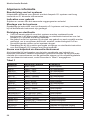
Table 1
Attachment Color Bars Category
SHORT-G1 YELLOW / YELLOW Straight Attachment
QD8-G1 BLACK / YELLOW QD Angle Attachment
QD8-S-GI BLACK / YELLOW QD Angle Attachment
MEDIUM-G1 ORANGE / ORANGE Straight Attachment
QD11-G1 BLACK / ORANGE QD Angle Attachment
QD11-S-G1 BLACK / ORANGE QD Angle Attachment
LONG-G1 RED / RED Straight Attachment
QD14-G1 BLACK / RED QD Angle Attachment
QD14-S-G1 BLACK / RED QD Angle Attachment
MIA16-G1 BLACK / BLACK Straight Attachment
SHORT-HD-G1 LIGHT BLUE / GREEN Straight Attachment
MEDIUM-HD-G1 LIGHT BLUE / YELLOW Straight Attachment
LONG-HD-G1 LIGHT BLUE / BLUE Straight Attachment
CRANI-A-G1 GREEN / GREEN Craniotome Attachment
CRANI-P-G1 TURQUOISE / TURQUOISE Craniotome Attachment
CRANI-L-G1 GOLD / GOLD Craniotome Attachment
MA-D20-G1 NA Minimal Access Attachment
CSR60-G1 NA Perforator Driver Attachment

3
English
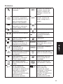
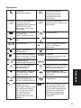
Symbols
Anspach Product Icon Reference Number
(A.K.A. Item Number,
Catalog Number, Part
Number)
Indicates the
attachment setting,
refer to MA-D20-G1
section in this document
for further details.
Lot (A.K.A. Lot
Number, Batch
Number, Batch Code)
Indicates position,
alignment, or location.
(Color: Black or Red)
Serial Number
Indicates position or
location
Temperature Limits
Direction of rotation
00/0000
Use By Date (A.K.A.
Expiration Date,
Expiry)
Run; System ready to
operate.
Manufacturer
Load; Insert attachment
and/or burr. System will
not operate.
Authorized European
Union Representative
Consult Operating
Instructions
Sterilized Using
Irradiation
CAUTION: Refer
to accompanying
documentation
Single Use Only
(A.K.A. Do Not Reuse)
Indicates position,
alignment, or location.
(Color: Black or Red)
Keep Dry (A.K.A.
Protect from Moisture)
DO NOT DISPOSE
OF IN HOUSEHOLD
WASTE
Sterile unless damaged
or open
United States Federal
law restricts this device
to sale by or on the
order of a physician or
other licensed health-
care provider
0086
CE Mark (A.K.A. CE
Mark [notied body
number], Conformité
Européenne) Meaning:
Device complies
with applicable EEC
Directives

4
English
Warnings
• ∆ Always use continuous irrigation to prevent heat build-up. Irrigation is
necessary for proper performance.
• Prior to rst use the equipment must be processed as per the included
Anspach G1 High Speed System Cleaning and Sterilization instructions.
• Do not use a dissection tool without an attachment, injury may occur.
• Only Use G1 Dissection Tools. Using other than indicated dissection tools
may lead to injury.
• Use the indicated dissection tool for the attachment, injury may occur.
• Surgeon is responsible for learning proper techniques in use of equipment;
improper use may cause serious injury to user or patient or damage to system.
• Instrument operator and all operating room personnel must wear eye
protection.
• Visually inspect for damage before using; do not use if damage is evident.
• Do not use if the product sterilization barrier or its packaging is compromised.
• Do not use, or discontinue use of powered equipment exhibiting excessive
temperatures that can cause patient injury (necrosis) and/or user discomfort.
• Use of damaged or improperly maintained power equipment and/or misused
powered equipment can result in excessive temperatures.
• Use caution to avoid cutting or tearing gloves while handling dissection tools.
• Dissection tools must be adequately retained within attachment to prevent
distal migration, which may cause injury. Conrm attachment is proper size
for dissection tool and that it is secure.
• Gently pull on dissection tool shaft to ensure it is fully seated and properly
installed.
• Only cut visible areas unless an image intensier is utilized.
• Delicate structures in proximity to dissection must be thoroughly protected to
prevent injury.
• Maintain rm control of instrument at all times.
• Do not bend or use as a lever.
• Use a gentle tapping motion or side-to-side motion and let instrument do cutting.
• Do not use excessive force.
• Forceful side loading of dissection tool may cause fracture of dissection tool,
which may cause injury.
• Use standard protocol for disposal of sharp instruments.
• Dissection tools are disposable and intended for single patient use only. Do
not re-sterilize and/or re-use dissection tools.
• Continuous extreme cutting at or near stalling conditions will quickly overheat
handpiece.
• Do not operate in an explosive ammable environment.
• Do not modify ground or power cord.
• Do not allow liquid into console.
• Use of accessories or cables other than those provided by DePuy Synthes
Power Tools and specied for use with eG1 System may result in increased
emissions or decreased immunity.

5
English
• The eG1should not be used adjacent to or stacked with other
equipment and that if adjacent or stacked use is necessary, the eG1
should be observed to verify normal operation in the conguration in
which it will be used
• Medical Electrical Equipment needs special precautions regarding
EMC and needs to be installed and put into service according to the
EMC information provided in this accompanying documentation.
• Portable and Mobile RF communications equipment can affect
Medical Electrical Equipment.
• Power source should comply with applicable IEC, CEC, and NEC
requirements. Grounding reliability can only be achieved when this
equipment is connected to a receptacle marked “HOSPITAL GRADE.”
• Do not use in oxygen rich environment.
• No modication of this equipment is allowed.
• Do not modify. Modications could result in loss of electrical safety.
• Dispose of items contaminated with body uids with other
biohazardous waste.
• At end of life recycle or dispose of device in accordance with local and
national regulations.
• To avoid the risk of electric shock, this equipment must only be
connected to a supply main with protective earth. The use of
Accessories, transducers, and cables other than those specied, with
the exception of transducers and cables sold by the Manufacturer of
this device as replacement parts for internal components, may result
in increased Emissions or decreased Immunity of the eG1 System.
Cautions
• United States Federal law restricts this device to sale by or on order of
a physician or other licensed healthcare provider.
• Do not use handpiece without an attachment and dissection tool properly
locked in place. Damage to the burr lock mechanism could occur.
• Do not use accessories other than those provided by DePuy Synthes
Power Tools and specied for use with Anspach Systems.
• To insure equipment operates as designed, read and follow
manufacturer’s instructions.
• Do not operate handpiece without an attachment and the
corresponding dissection tool.
• Only Anspach G1 Dissection Tools should be used with G1 Systems.
•
Use care to protect hose when handling, cleaning, and during system use.
• Damage to hose can cause leaking, rupture, or other related failures.
• Do not step on, set equipment on, pinch, kink, clamp, or otherwise
occlude handpiece hose during use.

6
English
Latex Information
Not made with natural rubber latex.
Warranty & Return Policies
Warranty and return policy is available upon request.
Warning: All Instrument System components returned for servicing or repair should
be properly cleaned and sterilized as applicable prior to shipping.
Warning: Transmissible Spongiform Encephalopathies (TSE)
DePuy Synthes Power Tools will not authorize or accept the return of products
that directly contact patients or are contaminated with a patient’s body uids who
is suspected or conrmed with a Transmissible Spongiform Encephalopathies/
Creutzfeldt-Jakob Disease (TSE/CJD) diagnosis. DePuy Synthes Power Tools
recommends that all Anspach products used on a patient conrmed with a
TSE/CJD diagnosis be incinerated. Anspach dissection tools used on a patient
suspected of TSE/CJD diagnosis must be incinerated.
Contact your Sales Representative for replacement of product incinerated under
this policy or for temporary equipment while original equipment is quarantined.
Contact the DePuy Synthes Power Tools Customer Service Department
regarding TSE/CJD contamination for additional information.

7
English
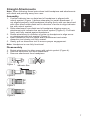
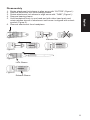
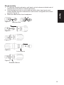
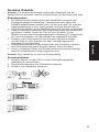
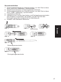
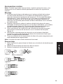
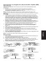
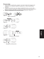
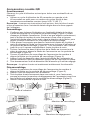
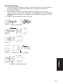
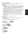
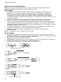
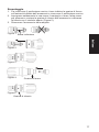
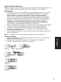
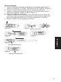
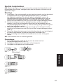
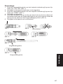
Straight Attachments
Note: When following these instructions hold handpiece and attachments
with distal end pointing away from user.
Assembly
1. Conrm indicator bar on distal end of handpiece is aligned with
unlock symbol (Figure 1) before attempting to install attachment. If
not aligned properly, hold handpiece housing rmly with one hand and
with other hand rotate distal end in direction of arrow to align indicator
bar with unlock symbol.
2. Slide attachment over distal end of handpiece aligning arrow on
attachment with indicator bar and unlock symbol (Figure 2). Pull back
rmly until fully seated against handpiece.
3. Rotate attachment in direction of arrow on handpiece to align arrow
on attachment with lock symbol (Figure 3).
4. Insert dissection tool into distal end of attachment and rotate
dissection tool slowly until fully seated.
5. Gently pull on dissection tool to ensure proper engagement.
Note: Handpiece is now fully functional.
Disassembly
1. Rotate attachment to align arrow with unlock symbol (Figure 4).
2. Remove dissection tool from attachment.
3. Remove attachment from handpiece.
Indicator Bar
Figure 3
Figure 2
Figure 4
Figure 1

8
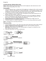
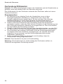
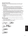
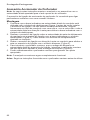
English
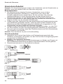
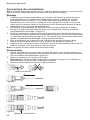
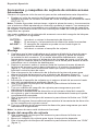
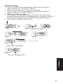
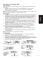
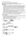
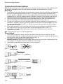
Craniotome Attachments
Note: When following these instructions hold handpiece and attachments with
distal end pointing away from user.
Assembly
1. Conrm indicator bar on distal end of handpiece is aligned with unlock symbol
(Figure 1) before attempting to install attachment. If not aligned properly, hold
handpiece housing rmly with one hand and with other hand rotate distal end
in direction of arrow to align indicator bar with unlock symbol.
2. Insert dissection tool into distal end of handpiece and rotate dissection tool
slowly until fully seated. (Figure 2).
3. Slide attachment over distal end of dissection tool and handpiece aligning
arrow on attachment with indicator bar and unlock symbol (Figure 3). Pull
back rmly until fully seated against handpiece.
4. Rotate attachment in direction of arrow on handpiece to align arrow on
attachment with lock symbol (Figure 4).
5. Visually inspect to conrm dissection tool is not touching attachment guard.
Note: Handpiece is now fully functional.
Disassembly
1. Hold handpiece rmly in one hand and with other hand push and rotate release
sleeve of attachment until arrow is aligned with unlock symbol (Figure 5).
2. Remove attachment from handpiece.
Warning: Use caution to avoid cutting hands or ngers on dissection tool
when performing this step.
3. Remove dissection tool from attachment.
Figure 3
Figure 4
Release Sleeve
Indicator Bar
Figure 2
Figure 1
Figure 5

9
English
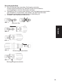
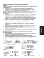
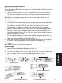
QD Angle Attachments
Warning
Observe the following duty cycle to avoid overheating of this device.
• Employ a duty cycle of 20 seconds ON and 40 seconds OFF for
an unlimited number of cycles at ambient temperatures up to 29°C
(85° F).
Note: When following these instructions hold handpiece and attachments
with distal end pointing away from user.
Assembly
1. Conrm indicator bar on distal end of handpiece is aligned with
unlock symbol (Figure 1) before attempting to install attachment. If
not aligned properly, hold handpiece housing rmly with one hand and
with other hand rotate distal end in direction of arrow to align indicator
bar with unlock symbol.
2. Slide attachment over distal end of handpiece aligning arrow on
attachment with indicator bar and unlock symbol (Figure 2). Pull back
rmly until fully seated against handpiece.
3. Rotate attachment in direction of arrow on handpiece to align arrow
on attachment with lock symbol (Figure 3).
4. Rotate attachment lock sleeve to align arrow with lock symbol
(Figure 4).
5. Insert dissection tool into distal end of attachment and rotate
dissection tool slowly until fully seated.
6. Gently pull on dissection tool to ensure proper engagement.
Note: Handpiece is now fully functional.
Disassembly
1. Rotate attachment lock sleeve to align arrow with unlock symbol
(Figure 5).
2. Remove dissection tool from attachment.
3. Hold handpiece rmly in one hand and with other hand push and
rotate release sleeve of attachment until arrow is aligned with unlock
symbol (Figure 6).
4. Remove attachment from handpiece.
Figure 3
Lock Sleeve
Indicator Bar
Figure 2
Lock Sleeve
Release Sleeve
Figure 1
Figure 4
Figure 6
Figure 5

10
English
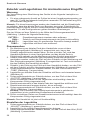
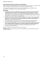
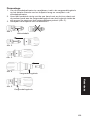
Minimal Access Attachment and
Bearing Sleeves
Warning
Observe the following duty cycle to avoid overheating of this device.
• Employ a duty cycle of 20 seconds ON and 40 seconds OFF for an unlimited
number of cycles at ambient temperatures up to 29°C (85° F).
Note: When following these instructions hold handpiece and attachments with
distal end pointing away from user. Minimal Access Attachments are compatible
with multiple bearing sleeve congurations. Instructions are the same for all
bearing sleeve congurations.
The four words labeled on attachment near lock sleeve (Figure 1) mean the
following:
CUTTER— Insert or remove dissection tool.
RUN— Attachment and dissection tool are now functional.
ADJUST— Bearing sleeve can be moved to desired exposure.
TUBE— Insert or remove bearing sleeve.
Assembly
1. Conrm indicator bar on distal end of handpiece is aligned with unlock
symbol (Figure 2) before attempting to install attachment. If not aligned
properly, hold handpiece housing rmly with one hand and with other hand
rotate distal end in direction of arrow to align indicator bar with unlock
symbol.
2. Slide attachment over distal end of handpiece aligning arrow on attachment
with indicator bar and unlock symbol (Figure 3). Pull back rmly until fully
seated against handpiece.
3. Rotate attachment in direction of arrow on handpiece to align arrow on
attachment with lock symbol (Figure 4).
4. Rotate attachment lock sleeve to align arrow with “TUBE” (Figure 1).
5. Insert bearing sleeve into distal end of attachment until fully seated (Figure
5).
6. Rotate attachment lock sleeve to align arrow with “CUTTER” (Figure 1).
7. Gently pull on bearing sleeve to ensure proper engagement.
8. Insert dissection tool into distal end of bearing sleeve and rotate dissection
tool slowly until fully seated.
9. Rotate attachment lock sleeve to align arrow with “RUN” (Figure 1).
Note: Additional force is required to seat dissection tool into curved bearing
sleeves.
10. Gently pull on dissection tool to ensure proper engagement.
Note: Handpiece is now fully functional.
Bearing Sleeve Adjustment
1. Rotate attachment lock sleeve to align arrow with “ADJUST”
(Figure 1).
2. Move bearing sleeve to desired exposure.
3. Rotate attachment lock sleeve to line up arrow with “RUN” (Figure 1).

11
English
Disassembly
1. Rotate attachment lock sleeve to align arrow with “CUTTER” (Figure 1).
2. Remove dissection tool from bearing sleeve.
3. Rotate attachment lock sleeve to align arrow with “TUBE” (Figure 1).
4. Remove bearing sleeve.
5. Hold handpiece rmly in one hand and with other hand push and
rotate release sleeve of attachment until arrow is aligned with unlock
symbol (Figure 6).
6. Remove attachment from handpiece.
Indicator Bar
Lock Sleeve
Figure 3
Figure 2
Figure 1
Figure 4
Release Sleeve
Figure 6
Figure 5

12
English
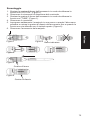
Perforator Driver Attachment
Note: When following these instructions hold handpiece and attachments with
distal end pointing away from user.
Perforator Driver Attachment is designed to connect to cranial perforators with a
Hudson connection.
Assembly
1. Conrm indicator bar on distal end of handpiece is aligned with unlock
symbol (Figure 1) before attempting to install attachment. If not aligned
properly, hold handpiece housing rmly with one hand and with other hand
rotate distal end in direction of arrow to align indicator bar with unlock
symbol.
2. Slide attachment over distal end of handpiece aligning arrow on attachment
with indicator bar and unlock symbol (Figure 2). Pull back rmly until fully
seated against handpiece.
3. Rotate attachment in direction of arrow on handpiece to align arrow on
attachment with lock symbol (Figure 3).
4. To insert cranial perforator, pull back on lock sleeve at distal end of
attachment, insert cranial perforator until fully seated and release lock sleeve
(Figure 4).
5. Gently pull on cranial perforator to ensure proper engagement.
Note: Handpiece is now fully functional.
Warning: Follow instructions supplied with cranial perforator before use.

13
English
Disassembly
1. To remove cranial perforator, pull back on lock sleeve at distal end of
attachment and remove cranial perforator.
2. Hold handpiece rmly in one hand and with other hand push and
rotate release sleeve of attachment until arrow is aligned with unlock
symbol (Figure 5).
3. Remove attachment from handpiece.
Indicator Bar
Figure 4
Figure 2
Figure 1
Figure 3
Release Sleeve
Figure 5
Lock Sleeve


Deutsch
G1-Hochgeschwindigkeits-
zubehör – Zusammen- und
Auseinanderbau


Deutsch
Inhalt
Allgemeines ....................................................................18
Gerades Zubehör ...........................................................23
Kraniotom-Zubehör.........................................................24
QD-Winkelzubehör .........................................................25
Zubehör und Lagerhülsen für
minimalinvasive Eingriff ..................................................26
Perforatorgriff-Zubehör ...................................................28

Deutsch-German
18
Allgemeines
Produktbeschreibung
Zubehörteile für das G1-Hochgeschwindigkeitssystem und
G1-Dissektionsinstrumente von Anspach.
Indikationen
Schneiden und Formen von Knochen, u. a. auch im Wirbelsäulen-
und Schädelbereich.
Systemzusammenbau
Siehe Anspach-Anweisungen für das eG1-Hochgeschwindigkeitssystem
im Lieferumfang der jeweiligen Vorrichtung.
Reinigung und Sterilisation
• Vor dem erstmaligen Gebrauch müssen die Instrumente gemäß
den im Lieferumfang enthaltenen Anspach-Reinigungs- und
Sterilisationsanweisungen für das Hochgeschwindigkeitssystem G1
aufbereitet werden.
• Nach Gebrauch ist das Gerät unmittelbar zu reinigen, damit Blut- und
Gewebereste sowie Zelltrümmer und Kontaminanten nicht antrocknen
können.
• Siehe Anspach-Reinigungs- und Sterilisationsanweisungen für das
Hochgeschwindigkeitssystem G1 im Lieferumfang dieser Vorrichtung.
Auswahl von Zubehör und Dissektionsinstrumenten
Zubehörteile sind am proximalen Ende farblich gekennzeichnet. Die jeweilige
Farbe entspricht der Codierung auf dem Etikett der Dissektionsinstrumente
und vereinfacht die Identizierung der richtigen Kombination aus Zubehör und
Dissektionsinstrument (siehe Tabelle 1 unten).
Tabelle 1
Zubehör Farbcode Kategorie
SHORT-G1 GELB/GELB Gerades Zubehör
QD8-G1 SCHWARZ/GELB QD-Winkelzubehör
QD8-S-GI SCHWARZ/GELB QD-Winkelzubehör
MEDIUM-G1 ORANGE/ORANGE Gerades Zubehör
QD11-G1 SCHWARZ/ORANGE QD-Winkelzubehör
QD11-S-G1 SCHWARZ/ORANGE QD-Winkelzubehör
LONG-G1 ROT/ROT Gerades Zubehör
QD14-G1 SCHWARZ/ROT QD-Winkelzubehör
QD14-S-G1 SCHWARZ/ROT QD-Winkelzubehör
MIA16-G1 SCHWARZ/SCHWARZ Gerades Zubehör
SHORT-HD-G1 HELLBLAU/GRÜN Gerades Zubehör
MEDIUM-HD-G1 HELLBLAU/GELB Gerades Zubehör
LONG-HD-G1 HELLBLAU/BLAU Gerades Zubehör
CRANI-A-G1 GRÜN/GRÜN Kraniotom-Zubehör
CRANI-P-G1 TÜRKIS/TÜRKIS Kraniotom-Zubehör
CRANI-L-G1 GOLD/GOLD Kraniotom-Zubehör
MA-D20-G1 —— Zubehör für minimalinvasive Eingriffe
CSR60-G1 —— Perforatorgriff-Zubehör
La page est en cours de chargement...
La page est en cours de chargement...
La page est en cours de chargement...
La page est en cours de chargement...
La page est en cours de chargement...
La page est en cours de chargement...
La page est en cours de chargement...
La page est en cours de chargement...
La page est en cours de chargement...
La page est en cours de chargement...
La page est en cours de chargement...
La page est en cours de chargement...
La page est en cours de chargement...
La page est en cours de chargement...
La page est en cours de chargement...
La page est en cours de chargement...
La page est en cours de chargement...
La page est en cours de chargement...
La page est en cours de chargement...
La page est en cours de chargement...
La page est en cours de chargement...
La page est en cours de chargement...
La page est en cours de chargement...
La page est en cours de chargement...
La page est en cours de chargement...
La page est en cours de chargement...
La page est en cours de chargement...
La page est en cours de chargement...
La page est en cours de chargement...
La page est en cours de chargement...
La page est en cours de chargement...
La page est en cours de chargement...
La page est en cours de chargement...
La page est en cours de chargement...
La page est en cours de chargement...
La page est en cours de chargement...
La page est en cours de chargement...
La page est en cours de chargement...
La page est en cours de chargement...
La page est en cours de chargement...
La page est en cours de chargement...
La page est en cours de chargement...
La page est en cours de chargement...
La page est en cours de chargement...
La page est en cours de chargement...
La page est en cours de chargement...
La page est en cours de chargement...
La page est en cours de chargement...
La page est en cours de chargement...
La page est en cours de chargement...
La page est en cours de chargement...
La page est en cours de chargement...
La page est en cours de chargement...
La page est en cours de chargement...
La page est en cours de chargement...
La page est en cours de chargement...
La page est en cours de chargement...
La page est en cours de chargement...
La page est en cours de chargement...
La page est en cours de chargement...
La page est en cours de chargement...
La page est en cours de chargement...
La page est en cours de chargement...
La page est en cours de chargement...
La page est en cours de chargement...
La page est en cours de chargement...
La page est en cours de chargement...
La page est en cours de chargement...
La page est en cours de chargement...
La page est en cours de chargement...
La page est en cours de chargement...
La page est en cours de chargement...
La page est en cours de chargement...
La page est en cours de chargement...
La page est en cours de chargement...
La page est en cours de chargement...
La page est en cours de chargement...
La page est en cours de chargement...
La page est en cours de chargement...
La page est en cours de chargement...
La page est en cours de chargement...
La page est en cours de chargement...
La page est en cours de chargement...
La page est en cours de chargement...
La page est en cours de chargement...
La page est en cours de chargement...
La page est en cours de chargement...
La page est en cours de chargement...
La page est en cours de chargement...
La page est en cours de chargement...
La page est en cours de chargement...
La page est en cours de chargement...
-
 1
1
-
 2
2
-
 3
3
-
 4
4
-
 5
5
-
 6
6
-
 7
7
-
 8
8
-
 9
9
-
 10
10
-
 11
11
-
 12
12
-
 13
13
-
 14
14
-
 15
15
-
 16
16
-
 17
17
-
 18
18
-
 19
19
-
 20
20
-
 21
21
-
 22
22
-
 23
23
-
 24
24
-
 25
25
-
 26
26
-
 27
27
-
 28
28
-
 29
29
-
 30
30
-
 31
31
-
 32
32
-
 33
33
-
 34
34
-
 35
35
-
 36
36
-
 37
37
-
 38
38
-
 39
39
-
 40
40
-
 41
41
-
 42
42
-
 43
43
-
 44
44
-
 45
45
-
 46
46
-
 47
47
-
 48
48
-
 49
49
-
 50
50
-
 51
51
-
 52
52
-
 53
53
-
 54
54
-
 55
55
-
 56
56
-
 57
57
-
 58
58
-
 59
59
-
 60
60
-
 61
61
-
 62
62
-
 63
63
-
 64
64
-
 65
65
-
 66
66
-
 67
67
-
 68
68
-
 69
69
-
 70
70
-
 71
71
-
 72
72
-
 73
73
-
 74
74
-
 75
75
-
 76
76
-
 77
77
-
 78
78
-
 79
79
-
 80
80
-
 81
81
-
 82
82
-
 83
83
-
 84
84
-
 85
85
-
 86
86
-
 87
87
-
 88
88
-
 89
89
-
 90
90
-
 91
91
-
 92
92
-
 93
93
-
 94
94
-
 95
95
-
 96
96
-
 97
97
-
 98
98
-
 99
99
-
 100
100
-
 101
101
-
 102
102
-
 103
103
-
 104
104
-
 105
105
-
 106
106
-
 107
107
-
 108
108
-
 109
109
-
 110
110
-
 111
111
-
 112
112


Anspach CRANI-A-G1 Assembly And Disassembly
- Taper
- Assembly And Disassembly
dans d''autres langues
- italiano: Anspach CRANI-A-G1
- English: Anspach CRANI-A-G1
- español: Anspach CRANI-A-G1
- Deutsch: Anspach CRANI-A-G1
- Nederlands: Anspach CRANI-A-G1
- português: Anspach CRANI-A-G1
Autres documents
-
Outsunny 867-024BU Mode d'emploi
-
 B.A. International BA-Optima BA121T Mode d'emploi
-
Bard Retro Instructions For Use Manual
-
NSK S-Max PICO Mode d'emploi
-
Stryker Harmonic Ace+7 Instructions For Use Manual
-
-
EMS PERIO-FLOW Operation Instructions Manual
-
-
DENTSPLY 57H Manuel utilisateur
-
