
BLODGETT COMBI
www.blodgett.com
44 Lakeside Avenue, Burlington, Vermont 05401 USA Telephone (800) 331-5842, (802) 860-3700 Fax: (802)864-0183
P N R 10382 R e v E (5/ 06)
E 2003 --- B lo dgett Combi
BC14E, BC14G,
BC14EDS, BC14GDS and B14G
COMBINATION OVEN STEAMER
INSTALLATION -- OPERATION -- MAINTENANCE
BC14E, BC14G,
BC14EDS, BC14GDS et B14G
COMBI-FOUR/ÉTUVE À VAPEUR
MANUEL D’INSTALLATION -- FONCTIONNEMENT -- ENTRETIEN

A PERSONAL WORD FROM BLODGETT COMBI
QUELQUES MOTS DE BLODGETT COMBI
Congratulations on your purchase of a BLODGETT Combi appliance. We
firmly believe that your choice has been a wise one, and trust you will re -
ceive many years of excellent service from your new Combi.
You will find that cooking with Combi appliances saves time, labor and
extensive cleaning of both the kitchen and the unit.
With Combi appliances the quality, taste, consistency, and look of your
food are improved, thus endorsing the policy to which we’ve always ad -
hered: “For Better Cooking!”
Once you’ve had a chance to use your Combi, please t ell us, your dealer
and colleagues about any creative and interesting applications you have
discovered; exchange ideas with other u sers. B e sure to advise us or
your dealer immediately should any mechanical or technical problems
be encountered (...we’re here to help!) and above all “Enjoy Cooking the
BLODGETT Combi Way!
F or information on cooking, please refer to our separate cooking guide.
Toutes nos félicitations sur votre achat d’appareil de Blodgett Combi.
Nous croyons fermement que votre choix est un choix raisonnable et
nous sommes certains que vous obtiendrez de nombreuses années
d’excellent service de votre nouveau four multi-usages.
V ous allez découvrir que la cuisson dans les appareils Combi économise
le temps, le travail et le degré de nettoyage de l’appareil aussi bien que
de la cuisine.
Avec les appareil de Combi, la qualité, le goût, la consistence et l’appar-
ence des aliments sont améliorés, s’accordant, de ce fait, avec notre
politique ”Pour une meilleure cuisson !”
Une fois que vous aurez eu la chance d’utiliser notre Combi, informez
nous, votre concessionnaire et vos collègues, de toutes les applications
nouvelles et intéressantes que vous avez découvertes ; échangez vos
idées avec d’autres utilisateurs. N’hésitez pas à nous prévenir, ou votre
concessionnaire, de tout problème mécanique ou technique que vous
pourriez rencontrer (.. . nous sommes ici pour vous aider) et par-dessus
tout “Régalez-vous à cuisiner à la façon BLODGETT Combi!
Pour obtenir de plus amples informations sur l’art culinaire, veuillez con-
sulter notre livre de cuisine séparé.

IMPORTANT
FORYOURSAFETY
Do not store or use gasoline or other flammable vapors or liquids in the vicinity
of this or any other appliance.
AVERTIS SEMENT
Ne pas entreposer ni utiliser de l’essence ni d’autres vapeurs ou liquides inflam-
mables dans le voisin a ge de cet appar iel, ni de to ut au tre appa r eil.
INSTRUCTIONS TO BE FOLLOWED IN THE EVENT THE USER SMELLS GAS
MUST BE POSTED IN A PROMINENT LOCATION. THIS INFORMATION MAY BE
OBTAINED BY CONTACTING YOUR LOCAL GAS SUPPLIER.
LES INSTRUCTIONS À RESPECTER AU CAS OÙ L’UTILISATEUR PERÇOIT UNE
ODEUR DE GAZ DOIVENT ÊTRE AFFICHÉES DANS UN ENDROIT BIEN VISIBLE.
VOUS POUVEZ VOUS LES PROCURER AUPRÈS DE VOTRE FOURNISSEUR DE
GAZ LOCAL.
WARNING: IMPROPER INSTALLA TION, ADJUSTMENT, ALTERA TION, SERVICE OR
MAI NTEN A NC E CAN CAUS E PROP ERTY DA MA GE, INJURY OR DEATH. READ THE
INST ALLA TION, OPERA TING AND MAINTENANCE INSTRUCTIONS THOROUGHLY
BEFORE INSTALLING OR SERVICING THIS EQUIPMENT
A V ERTI SSEMEN T: UNE IN S TALLATION , UN AJUSTEMEN T, UNE ALTÉRATIO N , UN
SERV IC E OU UN ENTRETI EN NON CO NFO RME A UX NORMES PEUT CAUSER DES
DO MMA GES À LA PRO P RI ÉTE, DES BLESSURES OU LA MORT. LIS EZ A TTENTI V E-
MENT LES DIRECTI V ESD’IN S TALLATIO N, D’OP ÉRATIO N ET D’EN TRETI EN A VA NT
DE FAI RE L’I NS TALLATIO N OU L’EN TRETI EN DE CET ÉQUIP EMEN T.
The information contained in thi s manual is important for the proper installation,
use, and maintenance of this oven. Adherence to these procedures and instruc-
tions will result in satisfactory baking results and long, trouble free service.
Please read this manual carefully and retain it for future reference.
Les info r m a t ions données dan s le présen t manuel so nt importantes pour installer,
utiliser et entreten ir cor r ect emen t ce f o u r. Le respect de ces instr u ctions et procé-
dures permettra d’obtenir de bons résultats de cuisso n et une longue durée de ser-
vice sans pro blèmes. Veuillez lire le présent manuel et le conserver pour pouvo ir
vou s y repo r t er à l’a ven ir.
Errors: Descriptive, typographic or pictorial errors are subject to correction. Specifica-
tions are subject to change without notice.
Erreurs:Les erreurs de description, de typographie ou d’illustration font l’objet de
corrections. Les caractéristiques sont sujettes à modifications sans préavis.

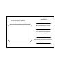
Your Service Agency’s Address:
Adressedevotreagencedeservice:
Model/ Modèl:
Serial Number/Numéro de série:
Your appliance was installed by/
Installateur de votre four:
Your oven’s installation was checked by/
Contrôleur de l’installation de votre four:

Table of Contents/Table des Matières
Introduction
The Blodgett Combi-Oven/Steamer 2.....
Description of the Combi-Oven/Steamer 3.
Oven Features 4.......................
Installation
Agency Approvals 5....................
Owner’s Responsibilities 6...............
Oven Location and Ventilation 9..........
Leg Attachment 10......................
Caster Attachment 11....................
Stacking 12.............................
Oven Leveling and Steam Connection 13...
Plumbing Connections 14................
Electrical Connections 15................
Gas Connections 16.....................
Gas Hose Restraint 18...................
Adjustments 19.........................
Final Check Lists 20.....................
Operation
Safety Information for Gas Units 22........
Gas Controls 23.........................
Standard Controls 24....................
Optional Cook & Hold 26.................
Optional Meat Probe 30..................
Maintenance
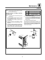
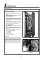
Spray Bottle Operating Procedure 31......
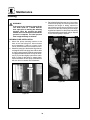
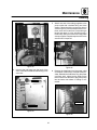
Cleaning and Preventive Maintenance 32...
Deliming 34.............................
Communication 41......................
Introduction
Le four-étuveur Combi de Blodgett 44......
Descriptiondufour-étuveurCombi 45......
Fonctionnalités du four 46................
Installation
Certifications 47.........................
Responsabilités du propriétaire 48.........
Emplacement du four et mise de niveau et
V entilation 51...........................
Montage des pieds 52...................
Accessoire des roulettes 53..............
Superposition 54........................
Mise de niveau du four et branchement
del la vapeur 55.........................
Raccordement de la plomberie 56.........
Raccordement à l’électricité 57............
Raccordement au gaz 58.................
Câble d’immobilisation du tuyau à gaz 60..
Ajustements 61.........................
Liste de vérification finale 62..............
F onctionnement
Renseignements sur la sécurité des
appareils a u gaz 64......................
Commandes du gaz 65..................
Commandes standard 66................
Cuisson et Pause en Option 68...........
Sonde thermique optionnelle 73...........
Entretien
Procédure de fonctionnement du
pulvérisateur 74.........................
Nettoyage et entretien préventif 75........
Détartrage 77...........................
Communications 84.....................

Introduction
2
The Blodgett Combi-Oven/Steamer
The Blodgett Combi -Oven/Steamer offers a com-
pletely new method of cooking. With the Oven/
Steamer you have the choice of two cooking pro -
cesses: Steam and Hot Air, either...
D Separately
D Combined, or
D In Sequence
And for easy operation you can choose from three
modes:
Steam Hot Air
Combi
Steam &
Hot Air
In the Steam mode you can:
steam reheat reconstitute
stew thaw simmer
blanch preserve braise
poach
In the Hot Air mode you can:
roast bake
grill gratinate
broil
In the Combination Steam and Hot Air mode you
can:
defrost roast rethermalize
reheat bake forced steaming
You can also use two or three functions in se-
quence during one cooking process. We call this:
D combi-steaming
D combi-roasting
D combi-baking
The combination of circulating hot air and steam
in the space saving, high performance Combi-
Oven/Steamer leads to improvements in the fol-
lowing areas:
D increased productivity in the kitchen
D a reduction in capital expenditures for multiple
equipment replacement
D a wider range of menu choices
D a simplified cleaning process
The work process is simplified since products are
prepared on or in steam table pans and t rays.
F ood can be cooked, stored, and transported with
the same pans. Small amounts of product can be
processed efficiently; pre-cooked and conve-
nience foods can be reheated within minutes.
Many frozen foods can be processed without pre-
thawing. This flexibility in preparation reduces the
need for kettles and steam tables since there is no
need for large amounts of food to be kept warm for
long periods of time.
Today the improvement of food quality is more im-
portant than ever. Vegetables are cooked in the
Blodgett Combi-Oven/Steamer w ithout water at
the optimal temperature of j ust under 100_C
(212_F), maintaining valuable vitamins, minerals,
nutrients and trace elements. Cooking meat in the
Combi results in less shrinkage and a firmer, juicier
product. The Blodgett Combi-Oven/Steamer is
being used more and more for baking. Steam and
Hot Air modes make it a general purpose baking
appliance.

Introduction
3
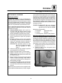
Description of the Combi-Oven/Steamer
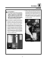
ABOUT THE OVEN/STEAMER
Blodgett Combi-Oven/Steamers are quality pro-
duced using high-grade stainless steel with first
class w orkmanship.
The two speed fan, which is guarded against acci-
dental finger contact, is driven by a quiet and pow-
erful motor. The condenser draws out excess
steam from the appliance. Condensation and
waste water, which result during steaming and
cleaning, are continuously drained.
The use of high quality insulation impedes exces-
sive heat radiation and saves energy.
The Oven/Steamer has optional adjustable legs
which adapt easily to slightly uneven surfaces and
optional floor stands which are designed for use
with all of the table models.
BC14E and BC14G only
The high performance fresh steam generator with
its control system makes it possible to enjoy all of
the advantages of a high quality steamer at the
flick of a sw itch. Fresh steam enters the oven cav-
ity without pressure and is circulated at high
speed. This process enables quick and gentle
cooking and ensures high quality food while pro-
viding convenient working methods. The steam
generator is completely automatic and protected
from running dry.
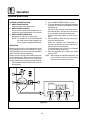
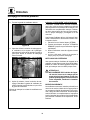
OVEN/STEAMER OPERATION
The practical oven door, with a viewing window,
has a wide swing radius and handle which can be
operated easily, even with wet or greasy hands.
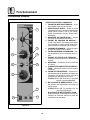
Ease of operation is guaranteed through the sim-
ple arrangement of the controls. Graphic symbols
make the a ppliance easy for even inexperienced
kitchen staff to operate. Steam, Hot Air and Combi
modes can be selected with one switch. The
Steam On Demand feature allows the operator to
add steam at any time for up to 8 minutes while op-
erating in either the hot air or Combi modes. This
feature is excellent for baking as well as roasting
operations. A fourth function on the mode selec-
tion switch, the Cool Down mode, allows the oven
cavity to cool down rapidly with the door opened.
The steam on demand function allow s the opera -
tor the ability to introduce steam into the cooking
process at any time.
Cleaning is kept to a minimum. The interior is
sprayed with a self-acting cleaning solution which
interacts w ith steam to easily remove crusts and
stains. The oven is designed for easy care and is
welded water tight so that the internal cooking
cavity may be rinsed with a hose after the steam
cleaning process.

Introduction
4
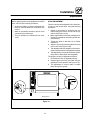
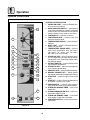
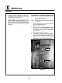
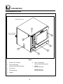
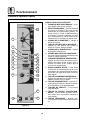
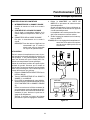
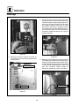
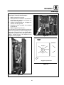
Oven Features
1
5
4
2
3
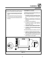
BC14E shown
7
Optional
Semi-Automatic
Deliming
6
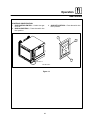
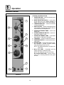
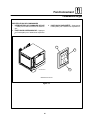
Figure 1
1 Control Panel
2 Power Connection
(BC14E and BC14EDS only)
3 Oven Door
4 Drip Collector
5 Door Handle
6 Deliming Port
(BC14E and BC14G only)
7Fuses
(BC14E only)
Gas Shutoff
(BC14G only)

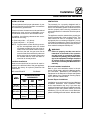
Installation
5
Agency Approvals
THE INSTA LLATION INSTRUCTIONS CON-
TAINED HEREIN ARE FOR THE USE OF QUALI-
FIED INSTALLATION AND SERVICE PERSONNEL
ONLY. INSTALLA TION OR SERVICE BY OTHER
THAN QUALIFIED PERSONNEL MAY RESULT IN
DAMAGE TO THE OVEN AND/ OR I NJURY TO
THE OPERATOR.
Qualified installation personnel are individuals, a
firm, a corporation, or a company which either in
person or through a representative are engaged
in, and are responsible for:
D The installation or replacement of gas piping.
The connection, installation, repair or servicing
of equipment.
D The installation of electrical wiring from the elec-
tric meter, main control box or service outlet to
the electric appliance.
Qualified installation personnel must be experi-
encedinsuchwork,befamiliarwithallprecau-
tions required and have complied with all require-
ments of state or local authorities having
jurisdiction.
U.S. and Canadian Installations
Installation must conform with local codes, or in
the absence of local codes, with t he National Fuel
Gas Code, NFPA54/ANSI Z223.1 ---Latest Edition,
the Natural Gas Installation Code CAN/CGA-
B149.1 or the Propane Installation Code, CAN/
CGA-B149.2 as applicable.
Reference: National Electrical Code, ANSI/NFPA
70---Latest Edition and/or Canadian Electrical
Code CSA C22.1 as applicable.
This equipment is to be installed in compliance
with the Basic Plumbing Code of the Building Offi -
cials and Code Administrators International Inc.
(BOCA) and the Food Service Sanitation Manual of
the Food and Drug Administration (FDA).
General Export Installations
Install atio n must conform with Lo cal and National
instal lati on standards. Lo cal installati on codes and/
or requirements may vary. If yo u have any questions
regarding the proper installation and/or operation of
your appliance, please contact your local distributo r.
If you do not have a lo cal distributor, please call
Blodgett Combi at 0011-802-860-3700.

Installation
6
Owner’s Responsibilities
Installation responsibil ities prior to service
startup inspection
You a re entitled to a free start-up inspection ser-
vice by our factory ASAP. Before a factory repre-
sentative arrives to perform a startup procedure,
the owner must already have satisfied the follow-
ing requirements.
1. Oven(s) are uncrated, stacked (if applies) and
put in place.
NOTE: Please refer to Leg Attachment and
Stacking.
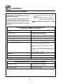
Maximum shelf loading -- 60 lbs (27.3 Kg)
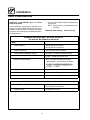
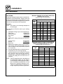
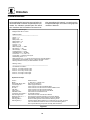
PLUMBING SPECIFICATIONS -- BC14E/AA, BC14G/AA,
BC14EDS/AA , BC14GDS/AA and B14G/AB
Water
Water Pressure 30 PSI (207 kPa) minimum
50 PSI (345 kPa) maximum
Water Connection 3/4” Hose Hot and Cold Water
Water Pressure Regulator Setting BC-14E/G --- Preset t o 30 PSI (207 kPa)
B-14G --- Preset to 3 PSI (21 kPa)
Minimum Requirements TDS --- less than 100 parts per million
Total Hardness --- 80-120 parts per million
C h lor i d es --- le s s t h a n 3 0 p a r t s p e r m i llion
pH Factor --- 7.0-8.0
Drainage Atmospheric Vented Drain
Drain Connection 2.00” (50.8mm) Copper
Avg Water Drain Temp. Approximately 160_F(71_C)
STEAM SPECIFICATIONS -- BC14EDS/AA and BC14GDS/AA
Steam Pressure 40 PSI (276 kPa) minimum
50 PSI (345 kPa) maximum
Steam Volume 60 lbs/hour per cavity

Installation
7
Owner’s Responsibilities
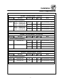
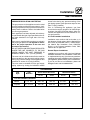
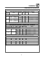
RATINGS -- GAS APPLIANCES -- BC14G/AA
Gas Type Gas Input Voltage Phase Amps Motor
U.S. and Canadian Installations
Natural Steam --- 55,000 BTU/Hr
H
o
t
A
i
r
6
5
0
0
0
B
T
U
/
H
r
208-240 1 15 1/2HP 208-240VAC, 50/60 Hz
H
ot
A
i
r --- 65,000
B
T
U
/
H
r
Total --- 115,000 BTU/Hr
120 1 15 1/2HP 208-240VAC, 50/60 Hz
Propane Steam --- 48,000 BTU/Hr
H
o
t
A
i
r
6
5
0
0
0
B
T
U
/
H
r
208-240 1 15 1/2HP 208-240VAC, 50/60 Hz
H
ot
A
i
r --- 65,000
B
T
U
/
H
r
Total --- 113,000 BTU/Hr
120 1 15 1/2HP 208-240VAC, 50/60 Hz
3/4” FNPT connector for all U.S. and Canadian installations
RATINGS -- GAS APPLIANCES -- BC14GDS/AA
Gas Type Gas Input Voltage Phase Amps Motor
U.S. and Canadian Installations
Natural 65,000 BTU/Hr
208-240 1 15 1/2HP 208-240VAC, 50/60 Hz
120 1 15 1/2HP 208-240VAC, 50/60 Hz
Propane 65,000 BTU/Hr
208-240 1 15 1/2HP 208-240VAC, 50/60 Hz
120 1 15 1/2HP 208-240VAC, 50/60 Hz
3/4” FNPT connector for all U.S. and Canadian installations
RATINGS -- GAS APPLIANCES -- B14G/AB
Gas Type Gas Input Voltage Phase Amps Motor
U.S. and Canadian Installations
Natural 65,000 BTU/Hr 120 1 15 1/2HP 208-240VAC, 50/60 Hz
Propane 65,000 BTU/Hr 120 1 15 1/2HP 208-240VAC, 50/60 Hz
3/4” FNPT connector for all U.S. and Canadian installations

Installation
8
Owner’s Responsibilities
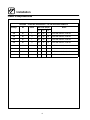
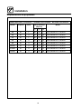
RATINGS -- ELECTRIC APPLIANCES -- BC14E/AA and BC14EDS/AA
Voltage Hz Phase
Max Load (amps)
Motor
L1 L2 L3
208 60 1 89 89 --- 1/2HP 208-240VAC, 50/60 Hz
208 60 3 52 52 52 1/2HP 208-240VAC, 50/60 Hz
240 60 1 82 82 --- 1/2HP 208-240VAC, 50/60 Hz
240 60 3 47 47 47 1/2HP 208-240VAC, 50/60 Hz
480 60 3 23 23 23 1/2HP 208-240VAC, 50/60 Hz
380/220 50 3 25 25 25 1/2HP 208-240VAC, 50/60 Hz
415/240 50 3 27 27 27 1/2HP 208-240VAC, 50/60 Hz
400/230 50 3 26 26 26 1/2HP 208-240VAC, 50/60 Hz

Installation
9
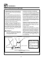
Oven Location and Ventilation
OVEN LOCATION
The well planned and proper placement of your
oven will result in long term operator convenience
and satisfactory performance.
Certain minimum clearances must be maintained
between the oven and any combustible or non-
combustible construction. See the table below.
In addition, the following clearances are recom-
mended for servicing.
D Oven body sides --- 12” (30cm)
D Oven body back --- 12” (30cm)
NOTE: On gas models, routine servicing can usu-
ally be accomplished within the limited
movement provided by the gas hose re-
straint. If the oven needs to be moved fur-
ther from the wall, the gas must first be
turned off and disconnected from the oven
before removing the restraint. Reconnect
the restraint after the oven has been re-
turned to its normal position.
Left Side Heat Shield
Heat sources should not be near the air vents lo-
cated on the left hand side of the gas appliance.
Consult the factory for optional protective side
heat shield.
BC14 and BC14D S P/N R9527
Oven
M
d
l
MINIMUM REQUIRED
CLEARANCES
Model
Right
Side
Left
Side
Back
BC14E
BC14EDS
1”
(25.4mm)
4”
(101.6mm)
6”
(152.4mm)
BC14G
BC14GDS
1”
(25.4mm)
6”
(152.4mm)
6”
(152.4mm)
B14G 0”
(0mm)*
0” (0mm) 6”
(152.4mm)
* 0” (0mm) clearance from hose hooks
VENTILATION
The necessity for a properly designed and in-
stalled ventilation system cannot be over empha-
sized. The ventilation system will allow the unit to
function properly while removing unwanted va-
pors and products of combustion from the operat-
ing area.
The a ppliance must be vented with a properly de-
signed mechanically driven exhaust hood. The
hood should be sized to completely cover the
equipment plus an overhang of a t least 6” (15 cm)
on all sides not adjacent to a wall. The capacity of
the hood should be sized appropriately and provi-
sions made for adequate makeup air.
WARNING!!
Failure to properly vent the oven can be
hazardous to the health of the operator;
and will result in operational problems,
unsatisfactory baking, and possible dam-
age to the equipment. Damage sustained
as a direct result of improper ventilation
will not be covered by the Manufacturer’s
warranty.
U.S. and Canadian Installations
Refer to your local ventilation codes. In the ab-
sence of local codes, refer to the National ventila-
tion code titled, “Standard for the Installation of
Equipment for the Removal of Smoke and Grease
Laden Vapors from Commercial Cooking Equip-
ment”, NFPA-96- Latest Edition.
General Export Installations
Installation must conform with Local and National
installation standards. Local installation codes
and/or requirements may vary. If you have any
questions regarding the proper installation and/or
operation of your unit, please contact your local
distributor. If you do not have a local distributor,
please call Blodgett Combi at 0011-802-860-3700.

Installation
10
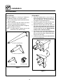
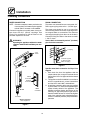
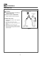
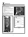
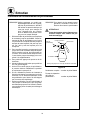
Leg Attachment
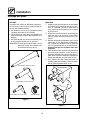
LEG OPTIONS
Legs are available in 4” (101mm), 6” (152mm) or
25” (635mm) lengths or low profile casters.
D The 4” (101mm) legs may be used when mount-
ing on a counter.
D The 6” (152.4mm) legs are used on the lower
section of a double stacked appliance.
D The 25” (635mm) legs are used for a single ap-
pliance located on the floor.
NOTE: For safety reasons, casters must not be
used with the 25” (635mm) legs.
4” (101mm) Leg
6” (152,4mm) Adjustable Leg
Low Profile Casters
25” (635mm) Adjustable Leg
Figure 2
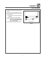
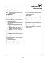
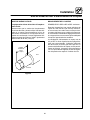
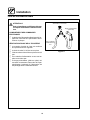
ATTACHMENT
1. Align the threaded stud on one of the front
legs to the bolt hole located in the bottom cor-
ner of the appliance. Turn the leg clockwise
and tighten to the nearest full turn.
2. Align the leg plate holes with the bolt holes.
Secure with the two 1/2” bolts provided.
3. Repeat the above steps with the other front
leg. If low profile casters are used, install them
with the locking casters in the front of the oven.
The rear casters do not lock. Ensure that the
locksaresetonthefrontcasters.
4. Tip t he oven up on the new ly installed front
legs. If casters are used, check that the locks
aresetonthefrontcasters.Repeat the above
steps for the rear legs.
5. Level the oven by screwing the adjustable feet
in or out as necessary.
Figure 3

Installation
11
Caster Attachment
1. Placealevelonthefloorwherethecastersare
to rest.
2. Place shims under the low side until it is level.
3. Mount the shims between the casters and the
oven as follows:
a.) Align the shims and caster holes with the
bolt holes.
b.) Secure with the 1/2” bolts provided.
NOTE: Install them with the locking casters in
the front of the oven. The rear casters
do not lock. Ensure that the locks are
setonthefrontcasters.
4. Tip the oven up on the newly installed casters.
Add shims as necessary
Exaggerated for clarity
Floor
Figure 4

Installation
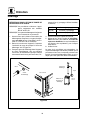
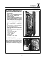
12
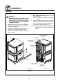
Stacking
WARNING!!
Stacking should be performed by quali-
fied installation personnel only. The ap-
pliances are heavy. Take care to use prop-
er tools and techniques when lifting and
stacking appliances.
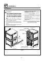
1. Removethedrippanfromthetopappliance.
2. Attach the legs or casters to the bottom ap-
pliance.Seepage10.
3. Place the top appliance on the bottom ap-
pliance. Be sure all four sides are flush.
4. Bolt the two appliances together using the
bolts provided.
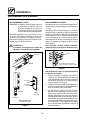
5. GAS APPLIANCES ONLY: Attach the flue
ventsasshown.
NOTE: For electric appliances proceed to
step 6.
6. Replace the drip pan. Push to the right until it
stops. The right side should overhand the ove n.
7. Connect the drain, gas (if applicable), electri-
cal and water. Refer to pages 14---18.
NOTE: An optional gas manifold may be purchased
from Blodgett Combi. Order part number
R9570.
Drip Pan
Steam Generator Flue
(BC14 only)
Gas Oven
Hot Air Flue
Rear View
BC14G Shown
Drain Assembly/
Steam Vent
1.125” I.D . Hose
from Drip Pan Drain
Optional
Gas Plumbing
Manifold
Mounting
Bracket
Figure 5

Installation
13
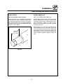
Oven Leveling and Steam Connection
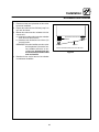
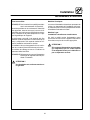
OVEN LEVELING
This oven should be set up in place.
With any stand or oven, be certain that the surface
is level, even and solid. A sloped or uneven base
may cause the appliance to function improperly.
Minor unevenness can be corrected by adjusting
the metal leg feet. The maximum adjustment of the
leg feet is 1-3/8” (35mm).
Maximum
Adjustment
1-3/8” (35mm)
Leg
F oot
Figure 6
STEAM CONNECTION
NOTE: BC14EDS and BC14GDS only.
Connect the appliance to a 40 to 50 psi maximum
external steam source per local or state codes.
The steam must be clean, potable and fit for hu-
man consumption. Failure to connect this ap-
pliance to a suitable steam source will revoke the
sanitation approval.
Steam supply line is 3/4” NPT. A particle screen
and bucket trap are recommended. 60 lbs per
hour is the maximum usage per oven. Steam sup-
ply pressure should not exceed 40 to 50 psi. The
flow pressure is 1-1/2 to 3-1/2 psi and is set at the
steam pressure regulator supplied inside the
oven.

Installation
14
Plumbing Connections
WATER CONNECTION
NOTE: Hot wat er maximizes stea m product ion but
is not requ ired. Cold wate r may be supplied
to both inle ts if hot wat e r is not availa ble .
Connect the appliance to quality water via a pres-
sure hose with 3/4” (19mm) couplings. See
Figure 7 for connections. A shut off valve is to be
provided adjacent to the oven.
WARNING!!
Operating the appliance without the water
regu lator ins t alle d will in v ali d at e your war-
ranty.
BC14E
Cold
Water
BC14G
Cold Water
Water Connections
Rear of Appliance
B14G
Filtered
Connection
Unfiltered
Connection
Cold Water
Figure 7
DRAIN CONNECTION
The steam vent assemblies are constructed of 2”
DWV copper piping reduced to 1-1/2 DWV pipe.
The steam vent should be run to an open floor
drain avoiding flexible hose that could sag and al-
low trapped water to accumulate. The customer
must supply the piping from the oven to the drain.
Connect the drip pan drain to the steam vent with
1.125 I.D. hose.
Use the drain vent assembly and a 2” (50.8mm)
pipe for drain connection.
Customer supplied
2” (50.8mm) drain
waste vent piping
Coupling
Figure 8
Specific water/drain connection for City of Los
Angeles
1. Each drain line fro m the appli ance shall be
routedwithoutdipsorsagstoterminateabove
the flood level rim of an approved indirect waste
receptor.
2. The appliance shall be installed in accordance
with the manufacturer’s printed instructions
and the LAPC and LAMC, 1999 editions.
3. A backflow protection device may be required
by local codes. If so, instal l on the potable water
system directly ahead of the appli ance. The
backflow protection device shall be any of the
foll o wing: an approved pressure type vacuum
breaker installed at least 12” abov e the highest
point of use, a double check valve backflow pre-
venter or a reduced pressure principal backflow
preventer.

Installation
15
Electrical Connections
ELECTRICAL CONNECTION
All Models
NOTE: Electrical connections must be performed
by a qualified installer only.
Before making any electrical connections to these
appliances, check that the power supply is ade-
quateforthevoltage,amperage,andphasere-
quirements stated on the rating name plate
mounted on the appliance.
The circuit breaker that is used t o provide power
to this appliance must have a minimum of .076”
(3mm) contact spacing. The circuit breaker must
meet all Local and National installation standards.
All appliances must be installed in a ccordance
with Local or National Electrical codes.
A wiring schematic is located on the inside of the
removeable side panel.
NOTE: Disconnect the power supply to the ap-
pliancebeforeservicing.
WARNING!!
Improper installation may invalidate your
warranty.
Electric Models
A strain relief for the power supply cord is required.
The installer must supply a cord bushing that meets
all Local and Natio nal installati o n standards.
Gas Models
U.S. and Canadian Installations
A power cord (115V or 230V) is supplied with a
plug attached. Plug the power cord into the de-
sired receptacle.
WARNING!!
If the supply cord is damaged, it must be
replaced by a special cord or assembly
available from the manufacturer or its ser-
vice agent.

Installation
16
Gas Connections
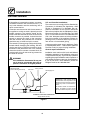
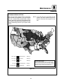
GAS PIPING
A properly sized gas supply system is essential for
maximum oven performance. Piping should be
sized to provide a supply of gas sufficient to meet
the maximum demand of all appliances on the line
without loss of pressure at the equipment.
Example:
NOTE: BTU values in the following example are
for natural gas.
You purchase a BC14G to add to your existing
cook line.
1. Add the BTU rating of your current appliances.
Pitco Fryer 120,000 BTU
6 Burner Range 60,000 BTU
Deck Oven 50,000 BTU
Total 230,000 BTU
2. Add the BTU rating of the new oven to the to-
tal.
Previous Total 230,000 BTU
BC14G 115,000 BTU
New Total 345,000 BTU
3. Measure the distance from the gas meter to
the cook line. This is the pipe length. Let’s say
thepipelengthis30’(9m)andthepipesize
is 1” (2.54 cm).
4. Use t he appropriate table to determine the to-
tal capacity of your current gas piping.
The total capacity for this example is 375,000
BTU. Since the total required gas pressure,
345,000 BTU is less t han 375,000 BTU, the
current gas piping will not have to be in-
creased.
NOTE: The BTU capacities given in the tables are
for straight pipe lengths only. Any elbows
or other fittings will decrease pipe capaci-
ties. For example: a schedule 40 1-1/2” ell
fitting has an equivalent capacity of 4.2”
(10.2 cm) of straight pipe. Contact your lo-
cal gas supplier if you have any questions.
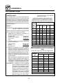
Maximum Capacity of Iron Pipe in Cubic Feet
of Natural Gas Per Hour
(Pressure drop of 0.5 Inch W.C.)
Pipe
L
e
n
g
t
h
Nominal Size, Inches
L
eng
t
h
(ft)
3/4” 1” 1-1/4” 1-1/2” 2”
10 360 680 1400 2100 3950
20 250 465 950 1460 2750
30 200 375 770 1180 2200
40 170 320 660 990 1900
50 151 285 580 900 1680
60 138 260 530 810 1520
70 125 240 490 750 1400
80 118 220 460 690 1300
90 110 205 430 650 1220
100 103 195 400 620 1150
From the National Fuel Gas Code Part 10 Table 10-2
Maximum Capacity of Pipe in Thousands of
BTU/hr of Undiluted P.P. Gas at 11” W.C.
(Pressure drop of 0.5 Inch W.C.)
Pipe Length
(
f
t
)
Inside Diameter, Inches
p
g
(ft)
3/4” 1” 1-1/2”
10 608 1146 3525
20 418 788 2423
30 336 632 1946
40 287 541 1665
50 255 480 1476
60 231 435 1337
70 215 404 1241
80 198 372 1144
90 187 351 1079
100 175 330 1014
From the National Fuel Gas Code Part 10 Table 10-15
La page charge ...
La page charge ...
La page charge ...
La page charge ...
La page charge ...
La page charge ...
La page charge ...
La page charge ...
La page charge ...
La page charge ...
La page charge ...
La page charge ...
La page charge ...
La page charge ...
La page charge ...
La page charge ...
La page charge ...
La page charge ...
La page charge ...
La page charge ...
La page charge ...
La page charge ...
La page charge ...
La page charge ...
La page charge ...
La page charge ...
La page charge ...
La page charge ...
La page charge ...
La page charge ...
La page charge ...
La page charge ...
La page charge ...
La page charge ...
La page charge ...
La page charge ...
La page charge ...
La page charge ...
La page charge ...
La page charge ...
La page charge ...
La page charge ...
La page charge ...
La page charge ...
La page charge ...
La page charge ...
La page charge ...
La page charge ...
La page charge ...
La page charge ...
La page charge ...
La page charge ...
La page charge ...
La page charge ...
La page charge ...
La page charge ...
La page charge ...
La page charge ...
La page charge ...
La page charge ...
La page charge ...
La page charge ...
La page charge ...
La page charge ...
La page charge ...
La page charge ...
La page charge ...
La page charge ...
La page charge ...
La page charge ...
-
 1
1
-
 2
2
-
 3
3
-
 4
4
-
 5
5
-
 6
6
-
 7
7
-
 8
8
-
 9
9
-
 10
10
-
 11
11
-
 12
12
-
 13
13
-
 14
14
-
 15
15
-
 16
16
-
 17
17
-
 18
18
-
 19
19
-
 20
20
-
 21
21
-
 22
22
-
 23
23
-
 24
24
-
 25
25
-
 26
26
-
 27
27
-
 28
28
-
 29
29
-
 30
30
-
 31
31
-
 32
32
-
 33
33
-
 34
34
-
 35
35
-
 36
36
-
 37
37
-
 38
38
-
 39
39
-
 40
40
-
 41
41
-
 42
42
-
 43
43
-
 44
44
-
 45
45
-
 46
46
-
 47
47
-
 48
48
-
 49
49
-
 50
50
-
 51
51
-
 52
52
-
 53
53
-
 54
54
-
 55
55
-
 56
56
-
 57
57
-
 58
58
-
 59
59
-
 60
60
-
 61
61
-
 62
62
-
 63
63
-
 64
64
-
 65
65
-
 66
66
-
 67
67
-
 68
68
-
 69
69
-
 70
70
-
 71
71
-
 72
72
-
 73
73
-
 74
74
-
 75
75
-
 76
76
-
 77
77
-
 78
78
-
 79
79
-
 80
80
-
 81
81
-
 82
82
-
 83
83
-
 84
84
-
 85
85
-
 86
86
-
 87
87
-
 88
88
-
 89
89
-
 90
90


dans d''autres langues
- English: Blodgett B14G Operating instructions
Documents connexes
-
Blodgett CNV14E Manuel utilisateur
-
-
-
-
Blodgett COS-8GDS Mode d'emploi
-
-
Blodgett COS6 spécification
-
-
-