
Installation
Instructions
Combined fridge-freezer for
integrated use, door-on-door
Instrucciones
de montaje
Combinado frigorífico-congelador,
integrable, puerta fija
Instructions
de montage
Combiné réfrigérateur-
congélateur, intégrable, porte fixe
HC 10..
151214 7085586 - 01

Contents
1 General safety information........................... 2
2 Transporting the appliance.......................... 2
3 Setting up the device.................................... 2
4 Appliance dimensions................................... 4
5 Recess dimensions....................................... 4
6 Cabinet door................................................... 5
7 Air circulation in the kitchen cabinet........... 7
8 Reversing the door........................................ 8
9 Water connection........................................... 12
10 Installing the appliance in the recess.......... 13
11 Disposal of packaging................................... 22
12 Connecting the appliance............................. 23
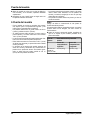
The manufacturer is constantly working to improve all
models. Therefore please understand that we reserve the
right to make design, equipment and technical modifica-
tions.
To get to know all the benefits of your new appliance,
please read the information contained in these instruc-
tions carefully.
The instructions apply to several models, so there may be
differences. Sections which only apply to certain appli-
ances are indicated with an asterisk (*).
Instructions for action are marked with a
, the
results of action are marked with a .
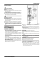
1 General safety information
-
Read and follow these instructions. They
contain safety advice which is important for
safe and problem-free installation and opera-
tion. Always read and follow the safety advice.
-
It is important that the guidelines and instruc-
tions in this manual are followed so that the
appliance is correctly installed and operates
properly Read and understand all information
in this manual before the appliance is installed
-
Risk of asphyxiation and crushing:
Remove doors and shelves from old appli-
ances to prevent them from becoming a poten-
tial hazard to children at play.
-
Only install, connect and dispose of the appli-
ance in accordance with the instructions. Pay
particular attention to “niche dimensions”
(see 5) and “ventilation and fume extraction in
kitchen units” (see 7) .
-
The socket must be easily accessible so that
the appliance can be disconnected from the
mains quickly in an emergency. It must not be
behind the back of the appliance.
DANGER indicates a hazardous situation,
which if not avoided, will result in
death or serious injury.
WARNING indicates a hazardous situation,
which if not avoided, could result in
death or serious injury.
CAUTION indicates a hazardous situation,
which if not avoided, will result in
minor or moderate injury.
NOTICE indicates a hazardous situation,
which if not avoided, could result in
damage to property.
Note indicates useful advice and tips.
2 Transporting the appliance
CAUTION
Risk of injury or damage if incorrectly transported.
u
Transport the appliance in its packaging.
u
Transport the appliance upright.
u
Do not move the appliance on your own.
3 Setting up the device
WARNING
Risk of fire due to short circuit.
If the power cable or plug of the appliance or another
appliance and the back of the appliance touch each other
the power cable or plug will be damaged by the vibrations
of the appliance which could lead to a short circuit.
u
Install the appliance so that it does not touch any plugs
or power cables.
u
Do not connect the appliance or other appliances to the
sockets on the back of the appliance.
WARNING
Risk of fire due to moisture!
If live parts or the power cord get wet, this can cause a
short circuit.
u
The appliance is designed for use in enclosed spaces.
Do not operate the appliance in open space or in damp
areas or where there is spray.
u
Only operate the appliance after it has been installed.
General safety information
2 * Depending on model and options

WARNING
Risk of fire due to refrigerant.
The refrigerant contained within the appliance, R 600a, is
environmentally friendly, but flammable. Leaking refrig-
erant can ignite.
u
Do not damage the pipes of the refrigerant circuit.
WARNING
Danger of fire and damage!
u
Do not place devices that give off heat, e.g. micro-
waves, toasters, etc. on the appliance.
NOTICE
Risk of damage caused by condensation
Installing the appliance next to any other refrigerator or
freezer can cause condensation or damage to the Lieb-
herr appliance.
u
Do not install this appliance next to any other refriger-
ator or freezer except another Liebherr model. Liebherr
models are designed to allow side-by-side installation.
They are equipped with a heating system to eliminate
condensation when refrigerators or freezers are
installed side-by-side.
NOTICE
Risk of damage for the finished floor surface!
u
Protect the finished floor surface before you uncrate the
unit.
WARNING
Danger of damage from overheating. May restrict opera-
tion.
u
Keep ventilation openings, in the appliance enclosure
or in the built-in structure, clear of obstruction.
WARNING
Danger of tilting.
u
To avoid a hazard due to instability of the appliance, it
must be fixed in accordance with the instructions.
q
If possible, have a professional install the appliance in
your kitchen cabinet unit.
q
If the appliance is damaged check with the supplier
immediately before connecting it.
q
The floor of the installation site must be horizontal and
level.
q
Do not install the appliance in direct sunlight or next to
an oven, heater or similar heat source.
q
Do not install the appliance on your own. It is better to
do this with two or more people.
q
The more R 600a refrigerant is in the appliance, the
larger the room must be where the device is located. In
the case of a leak, a flammable gas-air mixture may be
created in a room that is too small. In accordance with
standard EN 378, for every 0.39 oz (11 g) R 600a
coolant, the installation space must be at least35.5 ft
3
(1 m
3
). The amount of refrigerant in your appliance is
indicated on the identification plate inside the appli-
ance.
q
If the appliance is installed in a very damp environment
condensate water may form on the outside of the appli-
ance. Always ensure good ventilation.
q
The load-bearing capacity of the floor must be sufficient
for the weight of the appliance plus about 1200 pounds
(544 kg) of food weight.
q
The electrical socket must assessed precisely to
ensure the correct position and fuse.
q
Do not restrict ventilation. Sufficient ventilation is
required for the appliance to operate correctly. The
ventilation grid fitted at the factory guarantees an effec-
tive ventilation gap on the appliance of 31 in.
2
(200 cm
2
). If you replace the ventilation grid with a
fascia, this must have at least the same size or larger
ventilation gap as the manufacturer's ventilation grid.
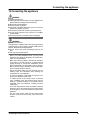
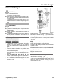
u
Note down the type (model, number), appliance name,
appliance or serial number, date of purchase and
manufacturer's address in the place provided for this in
the Use & Care Manual.
u
Remove all materials that could prevent it from being
installed properly or prevent proper ventilation from the
back or the side panels of the appliance.
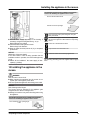
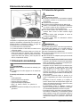
u
Remove the red transport
safety device. Close off any
holes that have been
revealed with plugs (60).
After installation:
u
Remove protective films, adhesive tapes and transport
safety devices, etc.
Note
u
Clean the appliance (see operating instructions,
"Cleaning the appliance" section).
Setting up the device
* Depending on model and options 3

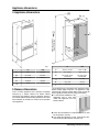
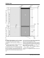
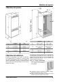
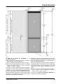
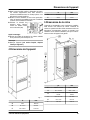
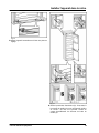
4 Appliance dimensions
Fig. 1
in. mm
A
22 in. 559 mm
B
21 7/16 in. 544 mm
C
69 11/16 in. 1770 mm
D
27 3/8 in. 695 mm
E
5/8 in. 15 mm
5 Recess dimensions
This is a built-in appliance and is therefore completely
enclosed by a kitchen cabinet The kitchen cabinet
surrounding the appliance must be designed exactly in
accordance with the specified fitting dimensions and must
allow sufficient air circulation to ensure correct operation
of the appliance.
Fig. 2
in. mm
F
69 3/4 — 70 3/8 1772 — 1788
G
22 — 22 3/4 560 — 578
H
min. 21 5/8, recom-
mended 22
min. 550, recom-
mended 560
J
min. 19 11/16 min. 500
K
min. 1 5/8 min. 40
L
max. 3/4 max. 19
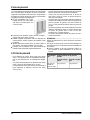
The declared energy consumption was determined with a
kitchen cabinet depth of 560 mm. The appliance is fully
functional with a kitchen cabinet depth of 550 mm but will
have a slightly increased level of energy consumption.
u
For side-by-side installation of two
appliances next to each other
install each appliance in its own
kitchen cabinet.
u
Check the wall thickness of adjacent cabinets: It must
be at least 5/8 in. (16 mm).
u
Only install the appliance in solid, fixed kitchen cabi-
nets. Ensure that the cabinets cannot tip over.
Appliance dimensions
4 * Depending on model and options

u
Align the cabinets with a spirit level and a try square. If
necessary level them by putting something underneath
them.
u
Ensure that the floor and the side panels of the cabinet
are at right angles to each other.
6 Cabinet door
-
Two doors are required for the kitchen cabinet: a top
one for the fridge section and a bottom one for the
freezer section.
-
The doors must be at least 5/8 in. (16 mm) and no more
than 3/4 in. (19 mm) thick.
-
When the two doors are closed the gap between the
top and bottom door must be at least 1/8 in. (3 mm).
-
The gap between the cabinet doors must be the same
as the gap between the appliance doors.
-
There must be a gap of at least 1/8 in. (3 mm) between
the door and the cupboard door above it (if there is
one).
-
The width of the cabinet doors depends upon the style
of the kitchen and the size of the gap between the door
panels of the cupboard. Normally a vertical gap of
1/8 in. (3 mm) should be left between the cabinet
doors.
-
The upper edges of the top door and the bottom door
should be the same as the on the cupboard(s) next to it
if there are any other cupboards.
-
The unit doors must be assembled flat and free from
tension.
NOTICE
An excessively heavy unit door can cause potential
damage!
If the unit door is too heavy, we cannot rule out damage to
the hinges, which may compromise the use of the unit.
u
Before installing the unit door, ensure the door does not
exceed the permissible weight.
Appliance
type
Maximum weight of unit door
Fridge compart-
ment door
Freezer compart-
ment door
HC 1030, HC
1050B, HC
1070, HC 1080
30.5 lbs (14 kg) 26.5 lbs (12 kg)
Cabinet door
* Depending on model and options 5

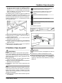
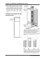
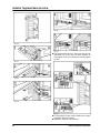
Fig. 3
The height of the freezer door is 24-24/32 in. (629 mm).
u
In order to cover the bottom section of the appliance:
extend the plate height to 27-3/8 in. (695 mm).
The thickness of the floor plate is normally 3/4 in.
(19 mm).
u
In order to cover the front of the floor plate
Fig. 3 (a)
:
extend the plate height to 27-3/8 in. + 3/4 in. =
28-1/8 in. ( 695 mm + 19 mm = 714 mm ).
If no cabinet doors have yet been fitted the gap between
the freezer section door
Fig. 3 (4)
and the fridge section
door
Fig. 3 (3)
is19/32 in. (15 mm) After the cabinet doors
have been fitted the gap between the two doors
Fig. 3 (1,2)
is about 1/8 in. (3 mm) and must be inside the hatched
area.
Of course, the final door height depends on the size of the
gap on the doors of the kitchen cabinets that are to the
right and left of the fitted appliance cabinet.
If there are other cabinets next to the fitted appliance
cabinet they normally have a gap between two drawers or
doors. Depending on the design of your kitchen these
gaps are about 1/8 in. (3 mm) wide.
u
In this case increase the plate height to 27-3/8 in. +
3/4 in. + 19/32 in. - 1/8 in. = 28-19/32 in. ( 695 mm +
19 mm + 15 mm - 3 mm = 726 mm ).
The height of the refrigerator door leaf is calculated as
follows:
Cabinet door
6 * Depending on model and options

u
Total height of the cupboard (i.e. 70-3/8 in. (1788 mm))
plus thickness of the cover and floor plate (normally
3/4 in. (19 mm)) minus the height of the freezer cabinet
door leaf (xxx in. (xxx mm)) as calculated above and
minus the gap width (approximately 1/8 in. (3 mm)):
70-3/8 in. + 3/4 in. + 3/4 in. - xxx in. - 1/8 in. = 71-3/4 in.
- xxx in. ( 1788 mm + 19 mm + 19 mm - xxx mm - 3 mm
= 1823 mm - xxx mm )
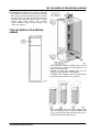
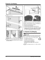
7 Air circulation in the kitchen
cabinet
Fig. 4
Fig. 5
-
There must be an effective ventilation gap of at least
31 in
2
(200 cm
2
) per appliance for the air inlet
Fig. 5 (A)
and the air outlet
Fig. 5 (B)
.
-
Basically, the bigger the ventilation gap, the more
energy-saving the operation of the appliance.
-
The depth of the ventilation shaft on the back wall of
the cabinet must be at least 1-1/2 in. (40 mm).
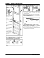
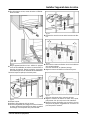
Fig. 6
-
The top ventilation gap can be set up either directly
above the appliance with an optional ventilation grid
Fig. 6 (C)
near the ceiling, above the cabinet
Fig. 6 (D)
or
as an air vent in a false ceiling
Fig. 6 (E)
.
Air circulation in the kitchen cabinet
* Depending on model and options 7

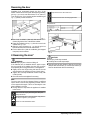
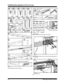
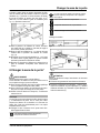
Ventilation from underneath through the floor of the
kitchen cabinet can be set up with the supplied ventilation
grid
Fig. 7 (3)
or an air vent with at least a 31 in
2
(200 cm
2
)
cross section area. If you use the supplied ventilation grid
Fig. 7 (1)
please proceed as follows:
Fig. 7
u
Cut a hole 17-23/32 in. (450 mm) wide and 2-7/32 in.
(56 mm) high in the floor of the kitchen cabinet.
u
Insert the ventilation grid
Fig. 7 (1)
into the cut out in the
cabinet floor
Fig. 7 (2)
.
u
Slide the snap connectors
Fig. 7 (3)
into the grid from
behind until the hooks touch the cabinet floor.
u
Fit the cabinet floor (with the ventilation grid snapped
into place) into the cabinet.
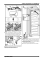
8 Reversing the door*
WARNING
Risk of bodily injury due to the door falling off.
If the fasteners are not installed with the proper torque,
the door may fall off. In addition, the door may not close,
thus impairing the cooling performance of the appliance.
u
Tightly secure the hinges along ball stud of the soft
stop mechanism by applying a torque of 3 lb-ft (4 Nm).
u
Tighten the soft stop mechanism retainer firmly with
2.5 lb-ft (3 Nm).
u
Check all screws and retighten if necessary.
Note
The door stop can only be changed if there is sufficient
space above to remove the hinge fixing bracket and fit it
on the opposite side again. This is not normally the case
when installing in a recess.
u
Change the door stop before the appliance is installed
in the recess.
There is the risk of injury when doing this. Obey the
safety instructions.
The instructions apply to several models. Only perform
this step if it applies to your appliance.
Select one of the alternatives shown.
Only undo the screw. Don't take it out.
Check the screws and if necessary tighten them.
Required tool:
Fig. 8
Fig. 9
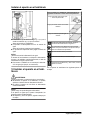
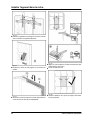
CAUTION
Risk of injury if soft stop contracts!
u
Carefully remove soft stop damper.
u
Removing the soft stop damper: Remove the soft stop
damper from the ball stud (1). Unscrew the retainer (2).
Remove the ball stud with a screwdriver (3).
Reversing the door
8 * Depending on model and options

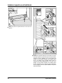
Fig. 10
u
Remove covers.
Fig. 11
u
Undo the screws on the hinges but do not remove
them.
Reversing the door
* Depending on model and options 9

Fig. 12
CAUTION
Hinges are spring-loaded and can cause pinching inju-
ries!
u
Leave hinges open.
u
Removing the door: Push the door forward and then
out, unhook it and put it to one side.
Fig. 13
u
Swap the hinges.
Reversing the door
10 * Depending on model and options

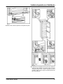
Fig. 14
u
Swap the fixing bracket to the opposite side.
Fig. 15
u
Fitting the door again: Reattach the door to the hinges
and tighten the screws.
Fig. 16
u
Re-attaching the soft stop mechanism: Screw in the
ball studs (1), tighten the retainer (2) and attach the soft
stop dampers into the ball studs.
Fig. 17
u
Check all screws and retighten if necessary.
u
Fit all covers except for the top left and the top right.
Only fit the top covers after installing the appliance into
the cabinet again.
Reversing the door
* Depending on model and options 11

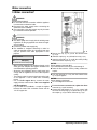
9 Water connection*
WARNING
Electrical Shock Hazard!
u
Do not make the water connection while the appliance
is connected to an electrical outlet.
u
Disconnect the water supply before connecting the
water lines for the IceMaker.
u
The connection to the water supply may only be made
by a trained and licensed plumber.
WARNING
Poisoning Hazard!
u
The water quality must comply with the drinking water
regulations for the geographical area where the appli-
ance is located.
u
Connect to potable water supply only.
u
The IceMaker is designed exclusively to make ice
cubes in quantities needed by a household and must
only be operated with water appropriate for this
purpose.
Water pressure:
psi MPa (bars)
21.76 to 87.02 0.15 to 0.6 (1.5 to 6)
- Water must be supplied to the appliance through a cold
water pipe that complies with hygiene standards and
can withstand the operating pressure.
- All devices and equipment used to supply water must
comply with the regulations in force in the respective
country.
- The solenoid valve is located at the bottom of the back
of the appliance. It has a metric R3/4 connecting
thread.
- Use a 1/4"-OD copper wire to connect the water
supply with the solenoid valve. This is not supplied
with the appliance.
- If your model has an IceMaker, a coupler is supplied
between the metric R3/4 connection thread and the
1/4"-OD copper wire.
Fig. 18
u
Remove the cap
Fig. 18 (1)
from the solenoid valve
Fig. 18 (2)
.
u
Insert the coupler
Fig. 18 (3)
in theunion nut
Fig. 18 (4)
.
u
Insert the water filter
Fig. 18 (5)
with the recess pointing
down towards the coupler
Fig. 18 (3)
.
NOTICE
Risk of damage to the water filter!
If you insert the filter incorrectly you could damage it.
u
Insert the filter with the recess pointing towards the
coupler.
u
Lock the union nut
Fig. 18 (4)
onto the solenoid valve
Fig. 18 (2)
and tighten.
NOTICE
Risk of damage to the thread!
u
Do not overtighten the union nut.
u
To turn the water connection 90°, tighten the elbow
connector
Fig. 18 (6)
if necessary.
u
Connect the water supply
Fig. 18 (7)
(e.g. copper) with
the aid of the clamp ring
Fig. 18 (8)
and nut
Fig. 18 (9)
to
the coupler
Fig. 18 (3)
or elbow connector
Fig. 18 (6)
.
Water connection
12 * Depending on model and options

Fig. 19
u
Affix the water supply
Fig. 19 (7)
to the housing, if
necessary, using the locking element
Fig. 19 (10)
.
Before fitting into the cabinet:
u
Check the whole water system for leaks.
Before using for the first time:
u
Have the water line bled (remove air) by a competent
professional.
NOTICE
Malfunction of the water intake!
If the water intake is shut off during operation but the
IceMaker remains in operation, the water intake pipe may
ice up.
u
Switch off the IceMaker if the water supply is inter-
rupted (e.g. holiday).
10 Installing the appliance in the
recess.
WARNING
Risk of fire due to short circuit.
u
When inserting the appliance into the recess do not
squash, jam or damage the power cable.
u
Do not operate the appliance with a faulty power cable.
NOTICE
Risk of damage to the hinges.
The hinges could be damaged if the appliance gets
caught on the door when it is being moved.
u
Always hold onto the body when relocating and moving
the appliance.
The following accessories are available from Customer
Services for installing the appliance into a recess :
Set to restrict the door opening angle
to 90°
The following accessories are available from Customer
Services for installing the appliance into a recess :
Set to fit divided cabinet fronts
Set with covers for top hinges
There is the risk of injury when doing this. Obey the
safety instructions.
The instructions apply to several models. Only perform
this step if the appliance is fitted with the corresponding
feature.
Select one of the alternatives shown.
Only undo the screw. Don't take it out.
Check the screws and if necessary tighten them.
The following assembly parts are supplied with the appli-
ance:
Installing the appliance in the recess.
* Depending on model and options 13

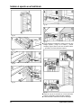
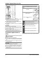
Fig. 20
The following tools are supplied with the appliance:
Fig. 21
The following tool is also required:
Fig. 22
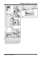
If the depth of the unit is
less than 21-3/4 in.
(553 mm) remove the
spacers on the back of the
appliance in order to be
able to push the appliance
completely into the recess.
Removing the spacers may
cause the appliance to use
more energy as this
reduces the ventilation
cross-section.
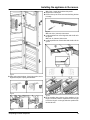
u
Undo the screw and remove the spacers.
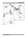
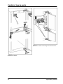
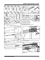
Fig. 23
u
Remove the top left cover and screw the fixing bracket
in loosely.
Fig. 24
u
Take off cover.
Installing the appliance in the recess.
14 * Depending on model and options

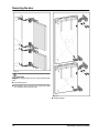
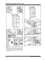
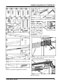
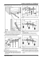
Fig. 25
u
Fitting spring steel brackets. If the fridge section door is
large use two pairs of spring steel brackets.
Fig. 26
Fig. 27
With 5/8 in. (16 mm) thick cabinet side panels:
u
clip spacers on all hinges.
u
Remove the top left cover and screw the fixing bracket
in loosely.
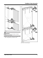
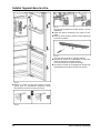
Fig. 28
With a 22 3/4 in. (578 mm) wide recess:
u
cut the equalizer trim on the hinge side with a knife to fit
the groove.
With a 22 in. (560 mm) wide recess:
u
cut the equalizer trim on both sides with a knife to fit the
groove.
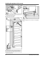
Fig. 29
u
Fit the equalizer trim to the top of the appliance. If the
hinge is on the left, slide the equalizer trim into the right
hook. If the hinge is on the right, slide the equalizer trim
into the left hook.
Installing the appliance in the recess.
* Depending on model and options 15

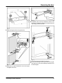
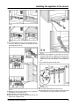
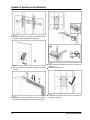
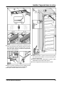
Fig. 30
u
Fasten the bottom left fixing bracket so that it does not
protrude beyond the side panel.
u
Clip the stop onto the bracket.
Fig. 31
u
Fit the strip: place at the top under the bracket and stick
to the side panel. The strip must not be shortened.
u
Remove the mains cable cleat and run the cable
upwards using a thread.
u
Push the appliance two thirds into the cabinet.
Fig. 32
u
Fit the adjusting feet to the bottom of the appliance
floor.
Installing the appliance in the recess.
16 * Depending on model and options

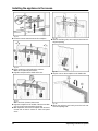
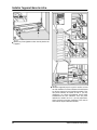
Fig. 33
u
Push the appliance in until the handle side above the
bracket and below the stop meets the front of the
cabinet side panel. With 5/8 in. (16 mm)thick cabinet
side panels the spacers on the hinge side must abut at
the same time. With 5/8 in. (16 mm)thick cabinet side
panels align the front edges of the hinges so that they
are flush with the front of the cabinet side panel.
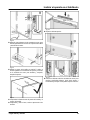
Fig. 34
u
If necessary align the appliance using the adjusting
feet.
Installing the appliance in the recess.
* Depending on model and options 17

Fig. 35
u
Checking the insertion depth (A): The distance
between the front edge of the cabinet and the appli-
ance body must be 1-21/32 '' (42 mm) all the way
along. If necessary make allowance for the stops on
the cabinet (d).
Fig. 36
Fig. 37
Fig. 38
Fig. 39
Installing the appliance in the recess.
18 * Depending on model and options

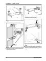
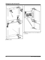
Fig. 40
Fig. 41
u
To fix the appliance in the recess: first hinge side up,
then down, then in the middle. Then handle side down
and finally handle side up.
Fig. 42
u
Remove the stop from the bracket on the handle side
and dispose of it. Re-attach cover.
u
Re-attach the cover on the hinge side.
u
Break the stop at the bottom of the handle side off and
dispose of it. Fitting the cover.
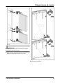
Fig. 43
u
Supporting the appliance at the bottom at the back:
Insert the handle into the stabilization rail and push the
stabilization rail into the appliance floor. Remove the
handle and do the same with the second stabilization
rail.
Carry out the steps below for both doors:
Fig. 44
u
Close the door.
u
Check the default setting of 5/16 in. (8 mm).
u
Raise fitting aids to unit door height. Bottom stop edge
of the fitting aid = top edge of the door to be fitted.
Installing the appliance in the recess.
* Depending on model and options 19

Fig. 45
u
Undo the counter nuts and remove the crosspiece.
Fig. 46
u
Hang crosspiece on the inside of the unit door.
With a 22 in. (560 mm) wide recess:
u
align the crosspiece to the middle of the door.
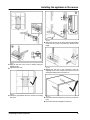
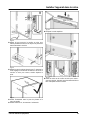
Fig. 47
With a 22 3/4 in. (578 mm) wide recess:
u
align the crosspiece to the middle of the door and then
3/16 (5.5 mm) move towards the hinge side.
u
With chipboard doors fit the crosspiece with at least 6
screws and at least 4 screws for frame and panel
doors.
Fig. 48
u
Remove the fitting aids, turn round and insert into the
adjacent opening.
Fig. 49
u
Clip the cover on the crosspiece on the handle side.
Fig. 50
u
Attach the unit door and loosely screw the lock nuts
onto the adjusting bolts.
Installing the appliance in the recess.
20 * Depending on model and options
La page est en cours de chargement...
La page est en cours de chargement...
La page est en cours de chargement...
La page est en cours de chargement...
La page est en cours de chargement...
La page est en cours de chargement...
La page est en cours de chargement...
La page est en cours de chargement...
La page est en cours de chargement...
La page est en cours de chargement...
La page est en cours de chargement...
La page est en cours de chargement...
La page est en cours de chargement...
La page est en cours de chargement...
La page est en cours de chargement...
La page est en cours de chargement...
La page est en cours de chargement...
La page est en cours de chargement...
La page est en cours de chargement...
La page est en cours de chargement...
La page est en cours de chargement...
La page est en cours de chargement...
La page est en cours de chargement...
La page est en cours de chargement...
La page est en cours de chargement...
La page est en cours de chargement...
La page est en cours de chargement...
La page est en cours de chargement...
La page est en cours de chargement...
La page est en cours de chargement...
La page est en cours de chargement...
La page est en cours de chargement...
La page est en cours de chargement...
La page est en cours de chargement...
La page est en cours de chargement...
La page est en cours de chargement...
La page est en cours de chargement...
La page est en cours de chargement...
La page est en cours de chargement...
La page est en cours de chargement...
La page est en cours de chargement...
La page est en cours de chargement...
La page est en cours de chargement...
La page est en cours de chargement...
La page est en cours de chargement...
La page est en cours de chargement...
La page est en cours de chargement...
La page est en cours de chargement...
La page est en cours de chargement...
La page est en cours de chargement...
La page est en cours de chargement...
La page est en cours de chargement...
-
 1
1
-
 2
2
-
 3
3
-
 4
4
-
 5
5
-
 6
6
-
 7
7
-
 8
8
-
 9
9
-
 10
10
-
 11
11
-
 12
12
-
 13
13
-
 14
14
-
 15
15
-
 16
16
-
 17
17
-
 18
18
-
 19
19
-
 20
20
-
 21
21
-
 22
22
-
 23
23
-
 24
24
-
 25
25
-
 26
26
-
 27
27
-
 28
28
-
 29
29
-
 30
30
-
 31
31
-
 32
32
-
 33
33
-
 34
34
-
 35
35
-
 36
36
-
 37
37
-
 38
38
-
 39
39
-
 40
40
-
 41
41
-
 42
42
-
 43
43
-
 44
44
-
 45
45
-
 46
46
-
 47
47
-
 48
48
-
 49
49
-
 50
50
-
 51
51
-
 52
52
-
 53
53
-
 54
54
-
 55
55
-
 56
56
-
 57
57
-
 58
58
-
 59
59
-
 60
60
-
 61
61
-
 62
62
-
 63
63
-
 64
64
-
 65
65
-
 66
66
-
 67
67
-
 68
68
-
 69
69
-
 70
70
-
 71
71
-
 72
72


dans d''autres langues
- English: Liebherr HC1030 Installation guide
- español: Liebherr HC1030 Guía de instalación
Documents connexes
-
Liebherr HC-1050B Guide d'installation
-
-
-
Liebherr SUIG 1514 Comfort Assembly And Installation Instructions
-
-
Liebherr UIK 1510 Assembly And Installation Instructions
-
-
Liebherr HC1540 Guide d'installation
-
-
Autres documents
-
Gaggenau WS 461 Manuel utilisateur
-
Gaggenau WS 482 Guide d'installation
-
-
V-ZUG 51077 Guide d'installation
-
Mitsubishi Electric MLP-448WU Room Air Conditioner Optional Grille Manuel utilisateur
-
GE Cafe Series CWS21SSESS Le manuel du propriétaire
-
GE PFSF0MFCBB Le manuel du propriétaire
-
Cafe™ CFCP1 Manuel utilisateur