Lincoln Electric K1780-1 Manuel utilisateur
- Catégorie
- Système de soudage
- Taper
- Manuel utilisateur
Ce manuel convient également à

Power Feed 10 Robotic
K1780-1
OPERATOR’S MANUAL
IM689-A
May, 2007
Safety Depends on You
Lincoln arc welding and cutting
equipment is designed and built
with safety in mind. However, your
overall safety can be increased by
proper installation ... and thought-
ful operation on your part. DO
NOT INSTALL, OPERATE OR
REPAIR THIS EQUIPMENT
WITHOUT READING THIS
MANUAL AND THE SAFETY
PRECAUTIONS CONTAINED
THROUGHOUT. And, most
importantly, think before you act
and be careful.
For use with machines having code numbers: 10729,10801
• Sales and Service through Subsidiaries and Distributors Worldwide •
Cleveland, Ohio 44117-1199 U.S.A. TEL: 216.481.8100 FAX: 216.486.1751 WEB SITE: www.lincolnelectric.com
• World's Leader in Welding and Cutting Products •
Copyright © 2007 Lincoln Global Inc.
This manual covers equipment which is no
longer in production by The Lincoln Electric Co.
Specications and availability of optional
features may have changed.

FOR ENGINE
powered equipment.
1.a. Turn the engine off before troubleshooting and maintenance
work unless the maintenance work requires it to be running.
____________________________________________________
1.b. Operate engines in open, well-ventilated
areas or vent the engine exhaust fumes
outdoors.
____________________________________________________
1.c. Do not add the fuel near an open flame
welding arc or when the engine is running.
Stop the engine and allow it to cool before
refueling to prevent spilled fuel from vaporiz-
ing on contact with hot engine parts and
igniting. Do not spill fuel when filling tank. If
fuel is spilled, wipe it up and do not start
engine until fumes have been eliminated.
____________________________________________________
1.d. Keep all equipment safety guards, covers and devices in
position and in good repair.Keep hands, hair, clothing and
tools away from V-belts, gears, fans and all other moving
parts when starting, operating or repairing equipment.
____________________________________________________
1.e. In some cases it may be necessary to remove safety
guards to perform required maintenance. Remove
guards only when necessary and replace them when the
maintenance requiring their removal is complete.
Always use the greatest care when working near moving
parts.
___________________________________________________
1.f. Do not put your hands near the engine fan.
Do not attempt to override the governor or
idler by pushing on the throttle control rods
while the engine is running.
___________________________________________________
1.g. To prevent accidentally starting gasoline engines while
turning the engine or welding generator during maintenance
work, disconnect the spark plug wires, distributor cap or
magneto wire as appropriate.
i
SAFETY
i
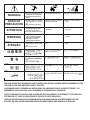
ARC WELDING CAN BE HAZARDOUS. PROTECT YOURSELF AND OTHERS FROM POSSIBLE SERIOUS INJURY OR DEATH.
KEEP CHILDREN AWAY. PACEMAKER WEARERS SHOULD CONSULT WITH THEIR DOCTOR BEFORE OPERATING.
Read and understand the following safety highlights. For additional safety information, it is strongly recommended that you
purchase a copy of “Safety in Welding & Cutting - ANSI Standard Z49.1” from the American Welding Society, P.O. Box
351040, Miami, Florida 33135 or CSA Standard W117.2-1974. A Free copy of “Arc Welding Safety” booklet E205 is available
from the Lincoln Electric Company, 22801 St. Clair Avenue, Cleveland, Ohio 44117-1199.
BE SURE THAT ALL INSTALLATION, OPERATION, MAINTENANCE AND REPAIR PROCEDURES ARE
PERFORMED ONLY BY QUALIFIED INDIVIDUALS.
WARNING
Mar ʻ95
1.h. To avoid scalding, do not remove the
radiator pressure cap when the engine is
hot.
CALIFORNIA PROPOSITION 65 WARNINGS
Diesel engine exhaust and some of its constituents
are known to the State of California to cause can-
cer, birth defects, and other reproductive harm.
The engine exhaust from this product contains
chemicals known to the State of California to cause
cancer, birth defects, or other reproductive harm.
The Above For Diesel Engines
The Above For Gasoline Engines
ELECTRIC AND
MAGNETIC FIELDS
may be dangerous
2.a. Electric current flowing through any conductor causes
localized Electric and Magnetic Fields (EMF). Welding
current creates EMF fields around welding cables and
welding machines
2.b. EMF fields may interfere with some pacemakers, and
welders having a pacemaker should consult their physician
before welding.
2.c. Exposure to EMF fields in welding may have other health
effects which are now not known.
2.d. All welders should use the following procedures in order to
minimize exposure to EMF fields from the welding circuit:
2.d.1.
Route the electrode and work cables together - Secure
them with tape when possible.
2.d.2. Never coil the electrode lead around your body.
2.d.3. Do not place your body between the electrode and
work cables. If the electrode cable is on your right
side, the work cable should also be on your right side.
2.d.4. Connect the work cable to the workpiece as close as
possible to the area being welded.
2.d.5. Do not work next to welding power source.
POWER FEED 10 / R

ii
SAFETY
ii
POWER FEED 10 / R
ARC RAYS can burn.
4.a. Use a shield with the proper filter and cover
plates to protect your eyes from sparks and
the rays of the arc when welding or observing
open arc welding. Headshield and filter lens
should conform to ANSI Z87. I standards.
4.b. Use suitable clothing made from durable flame-resistant
material to protect your skin and that of your helpers from
the arc rays.
4.c. Protect other nearby personnel with suitable, non-flammable
screening and/or warn them not to watch the arc nor expose
themselves to the arc rays or to hot spatter or metal.
ELECTRIC SHOCK can
kill.
3.a. The electrode and work (or ground) circuits
are electrically “hot” when the welder is on.
Do not touch these “hot” parts with your bare
skin or wet clothing. Wear dry, hole-free
gloves to insulate hands.
3.b. Insulate yourself from work and ground using dry insulation.
Make certain the insulation is large enough to cover your full
area of physical contact with work and ground.
In addition to the normal safety precautions, if welding
must be performed under electrically hazardous
conditions (in damp locations or while wearing wet
clothing; on metal structures such as floors, gratings or
scaffolds; when in cramped positions such as sitting,
kneeling or lying, if there is a high risk of unavoidable or
accidental contact with the workpiece or ground) use
the following equipment:
• Semiautomatic DC Constant Voltage (Wire) Welder.
• DC Manual (Stick) Welder.
• AC Welder with Reduced Voltage Control.
3.c. In semiautomatic or automatic wire welding, the electrode,
electrode reel, welding head, nozzle or semiautomatic
welding gun are also electrically “hot”.
3.d. Always be sure the work cable makes a good electrical
connection with the metal being welded. The connection
should be as close as possible to the area being welded.
3.e. Ground the work or metal to be welded to a good electrical
(earth) ground.
3.f.
Maintain the electrode holder, work clamp, welding cable and
welding machine in good, safe operating condition. Replace
damaged insulation.
3.g. Never dip the electrode in water for cooling.
3.h. Never simultaneously touch electrically “hot” parts of
electrode holders connected to two welders because voltage
between the two can be the total of the open circuit voltage
of both welders.
3.i. When working above floor level, use a safety belt to protect
yourself from a fall should you get a shock.
3.j. Also see Items 6.c. and 8.
FUMES AND GASES
can be dangerous.
5.a. Welding may produce fumes and gases
hazardous to health. Avoid breathing these
fumes and gases. When welding, keep
your head out of the fume. Use enough
ventilation and/or exhaust at the arc to keep
fumes and gases away from the breathing zone. When
welding with electrodes which require special
ventilation such as stainless or hard facing (see
instructions on container or MSDS) or on lead or
cadmium plated steel and other metals or coatings
which produce highly toxic fumes, keep exposure as
low as possible and below Threshold Limit Values (TLV)
using local exhaust or mechanical ventilation. In
confined spaces or in some circumstances, outdoors, a
respirator may be required. Additional precautions are
also required when welding on galvanized steel.
5. b. The operation of welding fume control equipment is affected
by various factors including proper use and positioning of
the equipment, maintenance of the equipment and the spe-
cific welding procedure and application involved. Worker
exposure level should be checked upon installation and
periodically thereafter to be certain it is within applicable
OSHA PEL and ACGIH TLV limits.
5.c.
Do not weld in locations near chlorinated hydrocarbon
vapors
coming from degreasing, cleaning or spraying operations.
The heat and rays of the arc can react with solvent vapors
to
form phosgene, a highly toxic gas, and other irritating prod-
ucts.
5.d. Shielding gases used for arc welding can displace air and
cause injury or death. Always use enough ventilation,
especially in confined areas, to insure breathing air is safe.
5.e. Read and understand the manufacturerʼs instructions for this
equipment and the consumables to be used, including the
material safety data sheet (MSDS) and follow your
employerʼs safety practices. MSDS forms are available from
your welding distributor or from the manufacturer.
5.f. Also see item 1.b.
AUG 06

iii
SAFETY
iii
POWER FEED 10 / R
FOR ELECTRICALLY
powered equipment.
8.a. Turn off input power using the disconnect
switch at the fuse box before working on
the equipment.
8.b. Install equipment in accordance with the U.S. National
Electrical Code, all local codes and the manufacturerʼs
recommendations.
8.c. Ground the equipment in accordance with the U.S. National
Electrical Code and the manufacturerʼs recommendations.
CYLINDER may explode
if damaged.
7.a. Use only compressed gas cylinders
containing the correct shielding gas for the
process used and properly operating
regulators designed for the gas and
pressure used. All hoses, fittings, etc. should be suitable for
the application and maintained in good condition.
7.b. Always keep cylinders in an upright position securely
chained to an undercarriage or fixed support.
7.c. Cylinders should be located:
• Away from areas where they may be struck or subjected to
physical damage.
• A safe distance from arc welding or cutting operations and
any other source of heat, sparks, or flame.
7.d. Never allow the electrode, electrode holder or any other
electrically “hot” parts to touch a cylinder.
7.e. Keep your head and face away from the cylinder valve outlet
when opening the cylinder valve.
7.f. Valve protection caps should always be in place and hand
tight except when the cylinder is in use or connected for
use.
7.g. Read and follow the instructions on compressed gas
cylinders, associated equipment, and CGA publication P-l,
“Precautions for Safe Handling of Compressed Gases in
Cylinders,” available from the Compressed Gas Association
1235 Jefferson Davis Highway, Arlington, VA 22202.
Jan 07
WELDING SPARKS can
cause fire or explosion.
6.a.
Remove fire hazards from the welding area.
If this is not possible, cover them to prevent
the welding sparks from starting a fire.
Remember that welding sparks and hot
materials from welding can easily go through small cracks
and openings to adjacent areas. Avoid welding near
hydraulic lines. Have a fire extinguisher readily available.
6.b. Where compressed gases are to be used at the job site,
special precautions should be used to prevent hazardous
situations. Refer to “Safety in Welding and Cutting” (ANSI
Standard Z49.1) and the operating information for the
equipment being used.
6.c. When not welding, make certain no part of the electrode
circuit is touching the work or ground. Accidental contact
can cause overheating and create a fire hazard.
6.d. Do not heat, cut or weld tanks, drums or containers until the
proper steps have been taken to insure that such procedures
will not cause flammable or toxic vapors from substances
inside. They can cause an explosion even
though
they have
been “cleaned”. For information, purchase “Recommended
Safe Practices for the
Preparation
for Welding and Cutting of
Containers and Piping That Have Held Hazardous
Substances”, AWS F4.1 from the American Welding Society
(see address above).
6.e. Vent hollow castings or containers before heating, cutting or
welding. They may explode.
6.f.
Sparks and spatter are thrown from the welding arc. Wear oil
free protective garments such as leather gloves, heavy shirt,
cuffless trousers, high shoes and a cap over your hair. Wear
ear plugs when welding out of position or in confined places.
Always wear safety glasses with side shields when in a
welding area.
6.g. Connect the work cable to the work as close to the welding
area as practical. Work cables connected to the building
framework or other locations away from the welding area
increase the possibility of the welding current passing
through lifting chains, crane cables or other alternate cir-
cuits. This can create fire hazards or overheat lifting chains
or cables until they fail.
6.h. Also see item 1.c.
6.I. Read and folllow NFPA 51B “ Standard for Fire Prevention
During Welding, Cutting and Other Hot Work”, available
from NFPA, 1 Batterymarch Park,PO box 9101, Quincy, Ma
022690-9101.
6.j. Do not use a welding power source for pipe thawing.

iv
SAFETY
iv
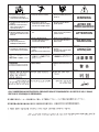
PRÉCAUTIONS DE SÛRETÉ
Pour votre propre protection lire et observer toutes les instructions
et les précautions de sûreté specifiques qui parraissent dans ce
manuel aussi bien que les précautions de sûreté générales suiv-
antes:
Sûreté Pour Soudage A LʼArc
1. Protegez-vous contre la secousse électrique:
a. Les circuits à lʼélectrode et à la piéce sont sous tension
quand la machine à souder est en marche. Eviter toujours
tout contact entre les parties sous tension et la peau nue
ou les vétements mouillés. Porter des gants secs et sans
trous pour isoler les mains.
b. Faire trés attention de bien sʼisoler de la masse quand on
soude dans des endroits humides, ou sur un plancher
metallique ou des grilles metalliques, principalement dans
les positions assis ou couché pour lesquelles une grande
partie du corps peut être en contact avec la masse.
c. Maintenir le porte-électrode, la pince de masse, le câble
de soudage et la machine à souder en bon et sûr état
defonctionnement.
d.Ne jamais plonger le porte-électrode dans lʼeau pour le
refroidir.
e. Ne jamais toucher simultanément les parties sous tension
des porte-électrodes connectés à deux machines à souder
parce que la tension entre les deux pinces peut être le
total de la tension à vide des deux machines.
f. Si on utilise la machine à souder comme une source de
courant pour soudage semi-automatique, ces precautions
pour le porte-électrode sʼapplicuent aussi au pistolet de
soudage.
2. Dans le cas de travail au dessus du niveau du sol, se protéger
contre les chutes dans le cas ou on recoit un choc. Ne jamais
enrouler le câble-électrode autour de nʼimporte quelle partie
du corps.
3. Un coup dʼarc peut être plus sévère quʼun coup de soliel,
donc:
a. Utiliser un bon masque avec un verre filtrant approprié
ainsi quʼun verre blanc afin de se protéger les yeux du ray-
onnement de lʼarc et des projections quand on soude ou
quand on regarde lʼarc.
b. Porter des vêtements convenables afin de protéger la
peau de soudeur et des aides contre le rayonnement de
lʻarc.
c. Protéger lʼautre personnel travaillant à proximité au
soudage à lʼaide dʼécrans appropriés et non-inflammables.
4. Des gouttes de laitier en fusion sont émises de lʼarc de
soudage. Se protéger avec des vêtements de protection libres
de lʼhuile, tels que les gants en cuir, chemise épaisse, pan-
talons sans revers, et chaussures montantes.
5. Toujours porter des lunettes de sécurité dans la zone de
soudage. Utiliser des lunettes avec écrans lateraux dans les
zones où lʼon pique le laitier.
6. Eloigner les matériaux inflammables ou les recouvrir afin de
prévenir tout risque dʼincendie dû aux étincelles.
7. Quand on ne soude pas, poser la pince à une endroit isolé de
la masse. Un court-circuit accidental peut provoquer un
échauffement et un risque dʼincendie.
8. Sʼassurer que la masse est connectée le plus prés possible
de la zone de travail quʼil est pratique de le faire. Si on place
la masse sur la charpente de la construction ou dʼautres
endroits éloignés de la zone de travail, on augmente le risque
de voir passer le courant de soudage par les chaines de lev-
age, câbles de grue, ou autres circuits. Cela peut provoquer
des risques dʼincendie ou dʼechauffement des chaines et des
câbles jusquʼà ce quʼils se rompent.
9. Assurer une ventilation suffisante dans la zone de soudage.
Ceci est particuliérement important pour le soudage de tôles
galvanisées plombées, ou cadmiées ou tout autre métal qui
produit des fumeés toxiques.
10. Ne pas souder en présence de vapeurs de chlore provenant
dʼopérations de dégraissage, nettoyage ou pistolage. La
chaleur ou les rayons de lʼarc peuvent réagir avec les vapeurs
du solvant pour produire du phosgéne (gas fortement toxique)
ou autres produits irritants.
11. Pour obtenir de plus amples renseignements sur la sûreté,
voir le code “Code for safety in welding and cutting” CSA
Standard W 117.2-1974.
PRÉCAUTIONS DE SÛRETÉ POUR
LES MACHINES À SOUDER À
TRANSFORMATEUR ET À
REDRESSEUR
1. Relier à la terre le chassis du poste conformement au code de
lʼélectricité et aux recommendations du fabricant. Le dispositif
de montage ou la piece à souder doit être branché à une
bonne mise à la terre.
2. Autant que possible, Iʼinstallation et lʼentretien du poste seront
effectués par un électricien qualifié.
3. Avant de faires des travaux à lʼinterieur de poste, la debranch-
er à lʼinterrupteur à la boite de fusibles.
4. Garder tous les couvercles et dispositifs de sûreté à leur
place.
Mar. ʻ93
POWER FEED 10 / R

vv
TThhaannkk YYoouu
for selecting a QUALITY product by Lincoln Electric. We want you
to take pride in operating this Lincoln Electric Company product
••• as much pride as we have in bringing this product to you!
Read this Operators Manual completely before attempting to use this equipment. Save this manual and keep it
handy for quick reference. Pay particular attention to the safety instructions we have provided for your protection.
The level of seriousness to be applied to each is explained below:
WARNING
This statement appears where the information must be followed exactly to avoid serious personal injury or loss of life.
This statement appears where the information must be followed to avoid minor personal injury or damage to this equipment.
CAUTION
Please Examine Carton and Equipment For Damage Immediately
When this equipment is shipped, title passes to the purchaser upon receipt by the carrier. Consequently, Claims
for material damaged in shipment must be made by the purchaser against the transportation company at the
time the shipment is received.
Please record your equipment identification information below for future reference. This information can be
found on your machine nameplate.
Product _________________________________________________________________________________
Model Number ___________________________________________________________________________
Code Number or Date Code_________________________________________________________________
Serial Number____________________________________________________________________________
Date Purchased___________________________________________________________________________
Where Purchased_________________________________________________________________________
Whenever you request replacement parts or information on this equipment, always supply the information you
have recorded above. The code number is especially important when identifying the correct replacement parts.
On-Line Product Registration
- Register your machine with Lincoln Electric either via fax or over the Internet.
• For faxing: Complete the form on the back of the warranty statement included in the literature packet
accompanying this machine and fax the form per the instructions printed on it.
• For On-Line Registration: Go to our
WEB SITE at www.lincolnelectric.com. Choose “Quick Links” and then
“Product Registration”. Please complete the form and submit your registration.
CUSTOMER ASSISTANCE POLICY
The business of The Lincoln Electric Company is manufacturing and selling high quality welding equipment, consumables, and cutting equip-
ment. Our challenge is to meet the needs of our customers and to exceed their expectations. On occasion, purchasers may ask Lincoln
Electric for advice or information about their use of our products. We respond to our customers based on the best information in our posses-
sion at that time. Lincoln Electric is not in a position to warrant or guarantee such advice, and assumes no liability, with respect to such infor-
mation or advice. We expressly disclaim any warranty of any kind, including any warranty of fitness for any customerʼs particular purpose,
with respect to such information or advice. As a matter of practical consideration, we also cannot assume any responsibility for updating or
correcting any such information or advice once it has been given, nor does the provision of information or advice create, expand or alter any
warranty with respect to the sale of our products.
Lincoln Electric is a responsive manufacturer, but the selection and use of specific products sold by Lincoln Electric is solely within the control
of, and remains the sole responsibility of the customer. Many variables beyond the control of Lincoln Electric affect the results obtained in
applying these types of fabrication methods and service requirements.
Subject to Change – This information is accurate to the best of our knowledge at the time of printing. Please refer to www.lincolnelectric.com
for any updated information.

vi
TABLE OF CONTENTS
Page
Installation .......................................................................................................Section A
Technical Specifications.......................................................................................................A-1
Safety Precautions ...............................................................................................................A-2
Mounting the Wire Drive Unit ........................................................................................A-2
Electrode Routing..........................................................................................................A-2
Electrode and Work Cable Connections .......................................................................A-2
Negative Electrode Polarity...........................................................................................A-3
Shielding Gas Connection.............................................................................................A-3
Control Cable .......................................................................................................................A-3
Control Cable Connections ...........................................................................................A-3
Control Cable Specifications .........................................................................................A-4
Wire Drive Gear Ratio (High or Low Speed) .................................................................A-4
Selecting the Proper Gear Ratio ...................................................................................A-4
Changing the Wire Drive Ratio......................................................................................A-5
Wire Feed Drive Roll Kits ..............................................................................................A-6
Procedure to Install Drive Rolls and Wire Guides .........................................................A-6
Drive Roll Kit Installation (KP1505-[ ]),(KP1507-[ ]) .................................................A-6
General Gun Connection Guidelines ............................................................................A-6
Gun Receiver Bushings and Adapters ..........................................................................A-7
Conduit Adapters ..........................................................................................................A-7
Remote Sense Lead Specifications ..............................................................................A-7
Installation of Field Installed Options ............................................................................A-7
Feeding Electrode and Brake Adjustment.....................................................................A-8
Drive Roll Pressure Setting ...........................................................................................A-8
Operation .........................................................................................................Section B
Safety Precautions ..............................................................................................................B-1
Duty Cycle.....................................................................................................................B-1
General Description ......................................................................................................B-1
Recommended Processes ............................................................................................B-1
Process Limitations .......................................................................................................B-1
Recommended Equipment / Interface...........................................................................B-1
Accessories.....................................................................................................Section C
Optional Equipment..............................................................................................................C-1
Drive Roll and Guide Tube Kits............................................................................................C-1
Maintenance ....................................................................................................Section D
Safety Precautions ...............................................................................................................D-1
Routine Maintenance ....................................................................................................D-1
Drive Rolls and Guide Tubes.............................................................................D-1
Avoiding Wire Feeding Problems..................................................................................D-1
Periodic Maintenance ...................................................................................................D-1
Procedure for Removing Feedplate from Wire Feeder ...........................................D-1
Troubleshooting..............................................................................................Section E
Safety Precautions ...............................................................................................................E-1
Troubleshooting Guide ...........................................................................................E-2 thru E-4
Diagrams ..........................................................................................................Section F
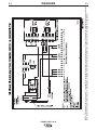
Wiring Diagram ......................................................................................................F-1
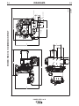
Dimension Print......................................................................................................F-2
Parts Lists...................................................................................................P-381 Series

POWER FEED 10 / R
A-1
INSTALLATION
A-1
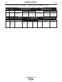
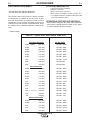
TECHNICAL SPECIFICATIONS – Power Feed 10 Robotic-K1780-1
WIRE DRIVE OR WIRE DRIVE SECTION OF FEEDER
SPEC.# TYPE LOW SPEED RATIO HIGH SPEED RATIO
Wire Size Wire Size
Speed Solid Cored Speed Solid Cored
K1780-1
Power Feed 10
50-800 IPM .025 - 3/32 in. .035 - .120 in 75 - 1200 IPM .025 - 1/16 in. .035 - 5/64 in.
(1.27-20.3 m/m) (0.6 - 2.4 mm) (0.9 - 3.2 mm) (2.03 - 30.5 m/m) (0.6 - 1.6 mm) (0.9 - 2.0 mm
CONTROL BOX, WIRE DRIVE AND COMPLETE UNITS
SPEC.# TYPE INPUT POWER PHYSICAL SIZE• TEMPERATURE RATING
Dimensions
Height Width Depth Weight Operating Storage
K1780-1
Power 40 VDC 13.5 “ 10.3 “ 12.0 “ 23.5 Lbs -20° to +40° C -40° to +40° C
Feed 10 (340 mm) ( 261 mm) (304 mm) (10.7 Kg)
Wire
Feeder

A-2
INSTALLATION
POWER FEED 10 / R
A-2
SAFETY PRECAUTIONS
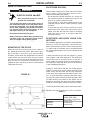
MOUNTING OF THE PF10/R
Mount the wire drive unit by means of the 4 holes in
the bottom of the wire drive base. Note that the gear-
box assembly is electrically “hot” when welding.
Therefore, make certain the gearbox does not come in
contact with the structure on which the unit is mount-
ed. The wire feed unit should be mounted so that the
drive rolls are in a vertical plane to prevent the accu-
mulation of dirt in the drive roll area. Do not bend the
conduit more than 45°.
FIGURE A.1
ELECTRODE ROUTING
The electrode supply may be either from reels, Readi-
Reels, spools, or bulk packaged drums or reels.
Observe the following precautions:
• Do not bend the conduit more than 45°, and to use
the minimum amount of conduit necessary for the
wire reel to connect to the wire feeder.
• The electrode is "hot" while welding and must be
insulated from the boom, conduit and wire payoff
structure.
• If more than one wire feed unit shares the same
boom and are not sharing the some power source
output stud, their wire and reels must be insulated
from each other as well as insulated from their
mounting structure.
ELECTRODE AND WORK CABLE CON-
NECTIONS
Most welding applications run with the electrode being
positive (+). For those applications, connect the elec-
trode cable between the wire feeder and the positive
(+) output stud on the power source (located beneath
the spring loaded output cover near the bottom of the
case front).
A work lead must be run from the negative (-) power
source output stud to the work piece. The work piece
connection must be firm and secure, especially if
pulse welding is planned. Excessive voltage drops at
the work piece connection often result in unsatisfacto-
ry pulse welding performance.
Connect a work lead of sufficient size and length (per
TABLE 1) between the proper output terminal on the
power source and the work. Be sure the connection
to the work makes tight metal-to-metal electrical con-
tact. To avoid interference problems with other equip-
ment and to achieve the best possible operation, route
all cables directly to the work or wire feeder. Do not
bundle the electrode and work leads tightly together.
Avoid excessive lengths and do not coil excess cable.
Use K1796 Coaxial welding cables wherever possible.
Minimum work and electrode cables sizes are as follows:
TABLE 1
Current (60% Duty Cycle)
400 Amps
500 Amps
600 Amps
ELECTRIC SHOCK can kill.
• Only qualified personnel should
perform this installation.
• Turn off the input power to the power source at
the disconnect switch or fuse box before work-
ing on this equipment. Turn off the input power
to any other equipment connected to the weld-
ing system at the disconnect switch or fuse
box before working on this equipment.
• Do not touch electrically hot parts.
• Always connect the Power Wave grounding lug
(located inside the reconnect input access
door) to a proper safety (Earth) ground.
----------------------------------------------------------------------------------------
MINIMUM COPPER WORK
CABLE SIZE, AWG
Up To-100 Ft. Length (30 m)
2/0 (67 mm2)
3/0 (85 mm2)
3/0 (85 mm2)
WARNING
7.11
1.77
1.77
1.97
3.05
.25 DIA.
(4 Places)
.22 DIA.
(2 Places)

A-3
INSTALLATION
POWER FEED 10 / R
A-3
When using an inverter type power source, Use the
largest welding (electrode and work) cables that are
practical. At least 2/0 copper wire - even if the aver-
age output current would not normally require it.
When pulsing, the pulse current can reach very high
levels. Voltage drops can become excessive, leading
to poor welding characteristics, if undersized welding
cables are used.
Connect the one end of the electrode cable, to the
power source output terminal of the desired polarity.
Connect the other end of the electrode cable to the
wire drive feed plate using the stud, lockwasher, and
nut provided on the wire drive feed plate. The elec-
trode cable lug must be against the feed plate. Be
sure the connection to the feed plate makes tight
metal-to-metal electrical contact. The electrode cable
should be sized according to the specifications given
in the work cable connections section.
NEGATIVE ELECTRODE POLARITY
When negative electrode polarity is required, such as
in some Innershield applications, reverse the output
connections at the power source (electrode cable to
the negative (-) stud, and work cable to the positive
(+) stud).
When operating with electrode polarity negative the
switch 7 must be set to OFF.
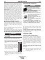
Set the Negative Polarity switch on Wire Feed Head
PC board as follows: These instructions apply to
the Power Wave 455/R and Power Wave 655/R.
Consult the manual for the power source if necessary.
1. Turn off power to the power source at the dis-
connect switch.
2. Remove the front cover from the power source.
3. The wire feed head board is on the right side of the
power source. Locate the 8-position DIP
switch and look for switch 7 of the DIP
switch.
4. Using a pencil or other small object,
slide the switch to the ON position for
negative electrode polarity. Conversely,
slide the switch to the OFF position for
positive electrode polarity.
5. Replace the cover and screws. The PC board will
“read” the switch at power up, automatically adjust-
ing all control parameters for the speed range
selected.
SHIELDING GAS CONNECTION
The customer must provide a cylinder of shielding
gas, a pressure regulator, a flow control valve, and a
hose from the flow valve to the gas inlet fitting of the
wire drive unit.
Connect a supply hose from the gas cylinder flow
valve outlet to the 5/8-18 female inert gas fitting on the
back panel of the wire drive or, if used, on the inlet of
the Gas Guard regulator.
CONTROL CABLE
CONTROL CABLE CONNECTIONS
The Power Wave / Power Feed Wire Feeders offer
flexibility in the connection of system components.
This system uses the same type of control cable
between all of the system components. Connections
can be “daisy chained” from one system component to
another. Components can be connected in any order,
as long as the proper input and output receptacles are
present.
Connect the control cable from the Power Feed 10
Robotic Wire Drive to the output receptacle on the
PowerWave.
NOTE: The maximum cable length between the
Power Feed 10 Robotic and the power source
is 100 feet (33 m).
O
N
1 2 3 4 5 6 7 8
CYLINDER may explode if damaged.
• Keep cylinder upright and chained
to support.
• Keep cylinder away from areas
where it may be damaged.
• Never lift welder with cylinder attached.
• Never allow welding electrode to touch cylin-
der.
• Keep cylinder away from welding or
other live electrical circuits.
BUILDUP OF SHIELDING GAS may
harm health or kill.
• Shut off shielding gas supply when
not in use.
SEE AMERICAN NATIONAL STANDARD Z-49.1,
“SAFETY IN WELDING AND CUTTING” PUB-
LISHED BY THE AMERICAN WELDING SOCIETY.
------------------------------------------------------------------------
WARNING
WARNING

A-4
INSTALLATION
POWER FEED 10 / R
A-4
CONTROL CABLE SPECIFICATIONS
It is recommended that genuine Lincoln control cables
be used at all times. Lincoln cables are specifically
designed for the communication and power needs of
the Power Wave / Power Feed system. The use of
non-standard cables, especially in lengths greater
than 25 feet, can lead to communication problems
(system shutdowns), poor motor acceleration (poor
arc starting) and low wire driving force (wire feeding
problems).
Lincoln control cables are copper 22 conductor cable
in a SO-type rubber jacket.
TABLE 2 (CONNECTOR WIRING)
AVAILABLE CABLE ASSEMBLIES:
K1795 Control cable only. Available in lengths of 25',
50' and 100'.
WIRE DRIVE GEAR RATIO (HIGH OR LOW
SPEED)
The speed range capability and drive torque of the
Power Feed wire drives can be easily and quickly
changed by changing the external drive gear. The
Power Feed Wire Feeders are shipped with both high
speed and a low speed gears. As shipped from the
factory, the low speed (high torque) gear is installed
on the feeder. If this is the desired gear ratio, no
changes need be made.
SELECTING THE PROPER GEAR RATIO
See Specification Section A-1 for feed speed and wire
size capabilities with high and low speed gear ratios.
To determine whether you should be using the high or
low speed ratio use the following guidelines:
• If you need to operate at wire feed speeds above
800 IPM (20 m/m), you will need to install the high
speed gear (large 30 tooth, 1.6 inch diameter gear).
• If you do not need to run at wire feed speeds in
excess of 800 IPM (20 m/m), you should use the low
speed gear (small, 20 tooth, 1.1 inch diameter gear).
Using the low speed ratio will provide the maximum
available wire driving force.
The full range of wire feed speed listed in Section A-1
may not be useable for all welding programs. Check
your welding software to make sure the desired WFS
falls within the welding software limits.
Pin
A
B
C
D
E
F
G
H
I
J
K
L
M
N
P
R
S
T
U
V
W
X
Lead #
841
844
842
843
845
846
847
67B
539
541
521
522
855A
Function
+15vdc Tach voltage
Tach common
Tach 1A differential signal
Tach 1B differential signal
Tach 2A differential signal
Tach 2B differential signal -
Single Tach Input
Reserved for future use
Voltage sense lead
Motor "+"
Motor "-"
Reserved for future use
Reserved for future use
+40vdc for solenoid
solenoid input
Reserved for future use
Reserved for future use
Shield ground to case
Reserved for future use
Reserved for future use
Reserved for future use
Reserved for future use

A-5
INSTALLATION
POWER FEED 10 / R
A-5
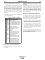
CHANGING THE WIRE DRIVE RATIO
ELECTRIC SHOCK can kill.
• Turn off power to the power source
at the disconnect switch.
------------------------------------------------------------------------
Changing the ratio requires a gear change and a PC
board switch change. The Power Feed Wire Feeders
are shipped with both high speed and a low speed
gears. As shipped from the factory, the low speed
(high torque) gear is installed on the feeder. For iden-
tification purposes, the low speed (high torque) gear
has 20 teeth and is 1.1 inches in diameter. The high
speed gear has 30 teeth and is 1.6 inches in diameter.
1. Pull open the Pressure Door.
2. Remove the Phillips head screw retaining the pinion
gear to be changed and remove the gear. If the
gear is not easily accessible or difficult to remove,
remove or adjust feed plate from the gearbox. To
remove feed plate:
• Loosen the clamping collar screw using a 3/16"
Allen wrench. The clamping collar screw is
accessed from the bottom of the feed plate. It is
the screw which is perpendicular to the feeding
direction.
• Loosen the retaining screw, which is also
accessed from bottom of feeder, using a 3/16"
Allen wrench. Continue to loosen the screw until
the feed plate can be easily pulled off of the wire
feeder.
3. Loosen, but do not remove, the screw on the lower
right face of the feed plate with a 3/16" Allen
wrench.
4. Remove the screw on the left face of the feed plate.
If changing from high speed (larger gear) to low
speed (smaller gear), line the lower hole on the left
face of the feed plate with the threads on the
clamping collar. Line the upper hole with the
threads to install larger gear for high speed feeder.
If feed plate does not rotate to allow holes to line
up, further loosen the screw on right face of feed
plate.
5. Remove the small gear from the output shaft.
Lightly cover the output shaft with engine oil or
equivalent. Install gear onto output shaft and secure
with flat washer, lock washer, and Phillips head
screw which were previously removed.
6. Tighten the screw on lower right face of feed plate.
7. Re-attach feed plate to wire feeder if removed in
Step 2.
8. Feed plate will be rotated out-of-position due to the
gear change. Adjust the angle of the feed plate per
Item 2.
Set the High/Low switch code on Wire Drive PC board
which is located on the Power Wave 455/R and
Power Wave 655/R. Consult the Instruction Manual
for proper power source settings.
WARNING

A-6
INSTALLATION
POWER FEED 10 / R
A-6
WIRE FEED DRIVE ROLL KITS
NOTE: The maximum rated solid and cored wire
sizes and selected drive ratios are shown on
the SPECIFICATIONS in the front of this sec-
tion.
The electrode sizes that can be fed with each roll and
guide tube are stenciled on each part. Check the kit
for proper components. Kit specifications can be
found in the ACCESSORIES section.
PROCEDURE TO INSTALL DRIVE ROLLS
AND WIRE GUIDES
DRIVE ROLL KIT INSTALLATION (KP1505-[ ])*
(KP1507-[ ])*
1. Turn OFF Welding Power Source.
2. Pull open Pressure Door to expose rolls and wire
guides.
3. Remove Outer Wire Guide by turning knurled
thumb screws counter-clock-wise to unscrew them
from Feedplate.
4. Remove drive rolls, if any are installed, by pulling
straight off shaft. Remove inner guide.
5. Insert inner Wire Guide, groove side out, over the
two locating pins in the feedplate.
6. Install each drive roll by pushing over shaft until it
butts up against locating shoulder on the drive roll
shaft. (Do Not exceed maximum wire size rating of
the wire drive).
7. Install Outer Wire Guide by sliding over locating
pins and tightening in place.
8. Engage upper drive rolls if they are in the “open”
position and close Pressure Door.
TO SET DRIVE ROLL PRESSURE, see “Drive Roll
Pressure Setting” in OPERATION.
GENERAL GUN CONNECTION GUIDELINES
The instructions supplied with the gun and K1500
series gun adapter should be followed when installing
and configuring a gun. The following guidelines are
general procedures only that are not intended to cover
all guns.
1. Check that the drive rolls and guide tubes are prop-
er for the electrode size and type being used.
2. Lay the cable out straight. Insert the connector on
the welding conductor cable into the brass conduc-
tor block on the front of the wire drive head. Make
sure it is all the way in and tighten the hand clamp.
Keep this connection clean and bright.
Note: For Fast-Mate and European connector style
guns, connect gun to gun connector making
sure all pins and gas tube line up with appropri-
ate holes in connector. Tighten gun by turning
the large nut on gun clockwise.
3. For GMA Gun Cables with separate gas fittings,
connect the gas hose from the wire drive unit to the
gun cable barbed fitting.
*See ACCESSORIES SECTION Table C.1, page C-1.
WARNING
WARNING
Observe all additional Safety Guidelines detailed
throughout this manual.
ELECTRIC SHOCK can kill.
• Do not touch electrically live parts such
as output terminals or internal wiring.
•
When feeding without Power Feed 10 “Cold
Feed” feature, electrode and drive mechanism
are “hot” to work and ground and could remain
energized several seconds after the gun trigger
is released.
• Turn OFF input power at welding power
source before installation or changing drive
roll and/or guide tubes.
• Welding power source must be connected
to system ground per the National Electrical
Code or any applicable local codes.
• Only qualified personnel should
perform this installation.

A-7
INSTALLATION
POWER FEED 10 / R
A-7
GUN RECEIVER BUSHINGS AND
ADAPTERS
The Power Feed wire feeders are equipped with facto-
ry installed K1500-2 gun connection kits. These kits
are for guns having a Tweco #2-#4 type connector.
The Power Feed 10/R has been designed to make
connecting a variety of guns easy and inexpensive
with the K1500 series of gun connection kits.
Non-Lincoln Guns
Most competitive guns can be connected to the Power
Feed 10/R by using one of the K1500 series adapter
kits, See “Gun Adapters” in ACCESSORIES section.
K489-7 (Dual Schedule Fast-Mate Adapter)
This adapter installs directly into the wire drive feed-
plate, to provide for use of guns with Fast-Mate or
European style gun connections. This K489-7 will
handle both standard Fast-Mate and Dual Schedule
Fast-Mate guns.
K1500-1 (Lincoln Innershield gun standard connec-
tion)
Use this kit to connect the following guns: Guns hav-
ing a Lincoln standard innershield gun connector,
Magnum 200/300/400 with K466-1 connector kit, and
Magnum 550 guns with the K613-1 gun connection
kit.
K1500-2 (Tweco #2-#4 type connection)
The K1500-2 gun adapter comes factory installed on
the Power Feed 10/R wire feeder. Use this adapter for
guns that have a Tweco #2-#4 connector. Such guns
include Magnum 200/300/400 guns with K466-2 con-
nector kit, and completely factory assembled Magnum
guns that are factory equipped with the K466-2 con-
nector (such as the K471-21, -22, and -23 dedicated
Magnum 400 guns and the K497-20 and -21 Magnum
200 guns).
K1500-3 (Tweco #5 connection)
For Magnum 550 gun with K613-2 Connection Kit,
and any other gun having a Tweco #5 connector .
K1500-4 (Miller connection)
For any gun having a newer style Miller connector.
Install gun adapters per the instructions shipped with it.
K1500-5 (Oxo connection)
For any gun having an Oxo style threaded connector.
Install gun adapter per the instructions shipped with it.
CONDUIT ADAPTERS
The K1546-1 and K1546-2 Adapter for use with
Lincoln Magnum conduit (K515 or 565) and E-Beam
conduit. The K1546-1 is to be used for wire sizes
(.023 - 1/16), K1546-2 is to be used for wire sizes
(1/16 - .120)
For Magnum conduit:
Install the K1546-1 or K1546-2 adapter at the incom-
ing end of the feed plate, secure with the set screw
located at the back of the feed plate. If a brass fitting
is supplied with the conduit, remove it from the feeder
end of the conduit by unscrewing it. Insert the conduit
into the K1546-1 or K1546-2, secure the conduit by
fastening it the adapter with the supplied knob screw.
For E-Beam Conduit:
Install the K1546-2 gun adapter at the incoming end of
the feed plate, secure with the set screw located at
the back of the feed plate. Insert the conduit into the
K1546-2, secure the conduit by fastening it the
adapter with the supplied knob screw.
REMOTE SENSE LEAD SPECIFICATIONS
The Power Feed10/R should always be operated with
the voltage sense lead (67) attached to the feed plate.
INSTALLATION OF FIELD INSTALLED
OPTIONS
Water Flow Sensor
Water cooled guns can be damaged very quickly if
they are used even momentarily without water flowing.
Recommend practice is to install a water flow sensor
on the water return line of the torch. When fully inte-
grated into the welding system, the sensor will prevent
welding if no water flow is present.
Gas Guard Regulator
The Gas Guard regulator is available as an optional
accessory (K659-1) for Power Feed Robotic wire drive
unit. Install the 5/8-18 male outlet of the regulator to
the proper 5/8-18 female gas inlet on the back panel
of the wire drive. Secure fitting with flow adjuster key
at top.

A-8
INSTALLATION
POWER FEED 10 / R
A-8
3. If the only result is drive roll slippage, disengage the
gun, pull the gun cable forward about 6" (150 mm).
There should be a slight waviness in the exposed
wire. If there is no waviness, the pressure is too
low. Increase the pressure setting 3 turns, recon-
nect the gun, tighten locking clamp and repeat the
above steps.
Feeding Electrode and Brake Adjustment
1. Turn the Reel or spool until the free end of the elec-
trode is accessible. If using a drum or large reel,
supply the electrode to the PF-10/R with an elec-
trode conduit. Minimize the number of bends in the
conduit and the distance the electrode must travel.
2. While tightly holding the electrode, cut off the bent
end and straighten the first 6" (150 mm). Cut off the
first 1" (25 mm). (If the electrode is not properly
straightened, it may not feed or may jam causing a
"bird nest".)
3. Insert the free end through the incoming guide tube.
4. Activate the Cold Inch mode until the the drive rolls
grab the electrode.
When feeding with the trigger, unless “Cold Feed”
trigger mode is selected the electrode and drive
mechanism are always “Hot” to work and ground
and could remain “Hot” several seconds after the
Gun trigger is released.
5. Feed the electrode through the gun.
6. Adjust the brake tension with the thumbscrew on
the spindle hub, until the reel turns freely but with
little or no overrun when wire feeding is stopped.
Do not over tighten.
Drive Roll Pressure Setting
The Power Feed 10/R drive roll pressures are factory
pre-set to about position “2” as shown on the pressure
indicator on the front of the feed plate door. This is an
approximate setting.
The optimum drive roll pressure varies with type of
wire, surface condition, lubrication, and hardness.
Too much pressure could cause “bird nesting,” but too
little pressure could cause wire feed slippage with
load and / or acceleration. The optimum drive roll set-
ting can be determined as follows:
1. Press end of gun against a solid object that is elec-
trically isolated from the welder output and press
the gun trigger for several seconds.
2. If the wire "bird nests", jams, or breaks at the drive
roll, the drive roll pressure is too great. Back the
pressure setting out 2 turns, run new wire through
gun, and repeat above steps.
WARNING

GENERAL DESCRIPTION
The Power Feed 10 Robotic is a high performance,
digitally controlled, modular wire feeder. Properly
equipped, it can support the GMAW, GMAW-P and
FCAW processes. The Power Feed wire feeders are
designed to be a part of a modular, multi-process
welding system. The Power Feed 10 Robotic is a 4
driven roll feeder that operates on 40VDC input
power.
The Power Feed Robotic wire feeders are designed to
be used with Robotic PowerWaves. Close integration
of the feeder, power source and customerʼs equip-
ment creates the foundation for a system with superior
welding performance.
The Power Feed 10 Robotic is intended for automatic
applications. It specifically designed to mount to a
robot arm or to use in hard automation applications.
Operation for the Power Feed 10 Robotic is with a
Power Feed compatible robotic power source.
RECOMMENDED PROCESSES
The Power Feed Wire Feeders can be set up in a
number of configurations. They are designed to be
used for GMAW, GMAW-P and FCAW for a variety of
materials, including mild steel, stainless steel, and
cored wires.
PROCESS LIMITATIONS
The feeders are capable of handling only some sub-
merged arc applications.
RECOMMENDED EQUIPMENT/INTERFACE
The Power Feed Robotic Feeders must be used with
PowerWave 455/R, PowerWave 655/R or other
Robotic PowerWave source. These are the only
power source to supply the correct operating voltage
(40 volts DC) and communication method (Arc-Link
digital communications) required by the Power Feed
10 Robotic.
B-1
OPERATION
POWER FEED 10 / R
B-1
SAFETY INSTRUCTIONS
Read and understand this entire section of operat-
ing instructions before operating the machine.
ELECTRIC SHOCK can kill.
• Unless using cold feed feature,
when feeding with gun trigger, the
electrode and drive mechanism are
always electrically energized and
could remain energized several sec-
onds after the welding ceases.
• Do not touch electrically live parts or electrodes
with your skin or wet clothing.
• Insulate yourself from the work and ground.
• Always wear dry insulating gloves.
FUMES AND GASES can be
dangerous.
• Keep your head out of fumes.
• Use ventilation or exhaust to
remove fumes from breathing zone.
WELDING SPARKS can cause
fire or explosion.
• Keep flammable material away.
• Do not weld on containers that have
held combustibles.
ARC RAYS can burn.
• Wear eye, ear, and body protection.
Observe additional Safety Guidelines
detailed in the beginning of this manual.
DUTY CYCLE
The Power Feed wire feeders are capable of welding
at a 100% duty cycle (continuous welding). The
power source will be the limiting factor in determining
system duty cycle capability.
WARNING

PLATFORM COMMONALITIES
• Power Feed 10 series Feedhead.
• CGA gas connections.
• Quick connect water connections.
• Works with all PowerWave ArcLink systems. “It is
not compatible with the PowerWave 350, 450 or 500
or Linc-net PowerWave 455ʼs”
OPERATIONAL FEATURES AND CONTROLS
• All procedure settings for the Power Feed 10 Robotic
wire feeder is through software control. A DIP switch
is used to indicate hardware settings.
C-1
ACCESSORIES
C-1
POWER FEED 10 / R
TABLE C.1 –
DRIVE ROLL AND GUIDE TUBE KITS
Wire Size
Solid Steel Electrode
KP No. Series
0.023” - 0.025” (0.6 mm) KP1505 - 030S
0.030” (0.8 mm) KP1505 - 030S
0.035” (0.9 mm) KP1505 - 035S
0.040” (1.0 mm) KP1505 - 045S
0.045” (1.2 mm) KP1505 - 045S
0.052” (1.4 mm) KP1505 - 052S
1/16” (1.6 mm) KP1505 - 1/16S
5/64” (2.0 mm) KP1505-5/64
3/32” (2.4 mm) KP1505-3/32
Cored Electrode
0.030 (0.8 mm) KP1505 - 035C
0.035” (0.9 mm) KP1505 - 035C
0.040” (1.0 mm) KP1505 - 045C
0.045” (1.2 mm) KP1505 - 045C
0.052” (1.4 mm) KP1505 - 052C
1/16” (1.6 mm) KP1505 - 1/16C
0.068” (1.7 mm) KP1505 - 068
5/64” (2.0 mm) KP1505 - 5/64
3/32” (2.4 mm) KP1505 - 3/32
7/64”
Lincore Hard Facing
(2.8mm) KP1505 - 7/64H
7/64” (2.8mm) KP1505 - 7/64
.120” (3.0mm) KP1505 - 120
Aluminum Electrode
0.035” (0.9 mm) KP1507 - 035A
0.040” (1.0 mm) KP1507 - 040A
3/64” (1.2 mm) KP1507 - 3/64A
1/16” (1.6 mm) KP1507 - 1/16A
3/32” (2.2 mm) KP1507 - 3/32A
OPTIONAL EQUIPMENT
• KP1505 Drive Roll and Wire Guide Kits
• KP1507 Drive Roll and Wire Guide Kits
The KP1507 series of drive roll kits contain a number
of components, in addition to the drive rolls, to opti-
mize the wire feeder for aluminum feeding. These
components are specifically designed to protect the
aluminum wire from abrasion and deformation, there-
by avoiding many common aluminum feeding prob-
lems.
• K1546 Conduit

D-1
MAINTENANCE
D-1
POWER FEED 10 / R
AVOIDING WIRE FEEDING PROBLEMS
Wire feeding problems can be avoided by observing
the following gun handling and feeder set up proce-
dures:
a) Do not bend the conduit more than 45°.
b) Keep the minimum amount of conduit necessary
for the wire reel to connect to the wire feeder.
c) Do not allow dolly wheels or trucks to run over
cables.
d) Keep cable clean by following maintenance
instructions.
e) Use only clean, rust-free electrode. The Lincoln
electrodes have proper surface lubrication.
f) Replace contact tip when the arc starts to become
unstable or the contact tip end is fused or
deformed.
g) Do not use excessive wire spindle brake settings.
h) Use proper drive rolls, wire guides and drive roll
pressure settings.
PERIODIC MAINTENANCE
Wire Drive Motor and Gearbox
Every year inspect the gearbox and coat the gear
teeth with a moly-disulfide filled grease. Do not use
graphite grease.
Every six months check the motor brushes. Replace
them if they are less than 1/4” long.
SAFETY PRECAUTIONS
ROUTINE MAINTENANCE
Drive Rolls and Guide Tubes
After feeding every coil of wire, inspect the feed plate
and drive rolls. Clean them as necessary.
All drive rolls have two identical grooves. The rolls
may be flipped over to use the other groove.
See “Procedure to Install Drive Rolls and Wire
Guides” in the INSTALLATION section for roll chang-
ing instructions.
WARNING
Observe all additional Safety Guidelines detailed
throughout this manual.
ELECTRIC SHOCK can kill.
• Do not touch electrically live parts such
as output terminals or internal wiring.
•
When inching with gun trigger, electrode and
drive mechanism are “hot” to work and
ground and could remain energized several
seconds after the gun trigger is released.
• Turn OFF input power at welding power
source before installation or changing
drive roll and/or guide tubes.
• Welding power source must be connected
to system ground per the National
Electrical Code or any applicable local
codes.
• Only qualified personnel should
perform maintenance work.

E-1
TROUBLESHOOTING
E-1
POWER FEED 10 / R
If for any reason you do not understand the test procedures or are unable to perform the tests/repairs safely, contact your
Local Lincoln Authorized Field Service Facility for technical troubleshooting assistance before you proceed.
CAUTION
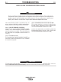
This Troubleshooting Guide is provided to help you
locate and repair possible machine malfunctions.
Simply follow the three-step procedure listed below.
Step 1. LOCATE PROBLEM (SYMPTOM).
Look under the column labeled “PROBLEM (SYMP-
TOMS)”. This column describes possible symptoms
that the machine may exhibit. Find the listing that
best describes the symptom that the machine is
exhibiting.
Step 2. POSSIBLE CAUSE.
The second column labeled “POSSIBLE CAUSE” lists
the obvious external possibilities that may contribute
to the machine symptom.
Step 3. RECOMMENDED COURSE OF ACTION
This column provides a course of action for the
Possible Cause, generally it states to contact your
local Lincoln Authorized Field Service Facility.
If you do not understand or are unable to perform the
Recommended Course of Action safely, contact your
local Lincoln Authorized Field Service Facility.
HOW TO USE TROUBLESHOOTING GUIDE
Service and Repair should only be performed by Lincoln Electric Factory Trained Personnel.
Unauthorized repairs performed on this equipment may result in danger to the technician and
machine operator and will invalidate your factory warranty. For your safety and to avoid Electrical
Shock, please observe all safety notes and precautions detailed throughout this manual.
__________________________________________________________________________
WARNING

E-2
TROUBLESHOOTING
E-2
POWER FEED 10 / R
Observe all Safety Guidelines detailed throughout this manual
If for any reason you do not understand the test procedures or are unable to perform the tests/repairs safely, contact your
Local Lincoln Authorized Field Service Facility for technical troubleshooting assistance before you proceed.
CAUTION
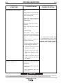
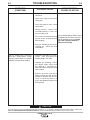
PROBLEMS
(SYMPTOMS)
POSSIBLE CAUSE
RECOMMENDED
COURSE OF ACTION
Rough wire feeding or wire not
feeding but drive rolls are turning.
Variable or “hunting” arc.
1. Gun cable kinked and / or twist-
ed.
2. Wire jammed in gun and cable.
Check for mechanical restric-
tions in feeding path.
3. Check for current position of
drive rolls relative to split wire
guide groove.
4. Drive rolls may not be seated
properly.
5. Gun cable dirty, clean if neces-
sary.
6. Worn drive roll.
7. Electrode rusty and/or
dirty.Cable frayed, or poor sol-
der joint at work or electrode
lug.
8. Worn nozzle or cable liner.
Replace if necessary.
9. Partially flashed or melted con-
tact tip. Replace if necessary.
10. Incorrect drive roll pressure.
Readjust if necessary.
11. Improper liner, tip or inner /
outer guides. Replace if neces-
sary.
12. Incorrect wire drive or gear
ratio selection on the control
P.C. board.
1. Wrong size, worn and/or melted
contact tip.
2. Worn work cable or poor work
connection.
3. Loose electrode or work cable
connections.
If all recommended possible areas
of misadjustment have been
checked and the problem persists,
Contact your local Lincoln
Authorized Field Service Facility.
La page est en cours de chargement...
La page est en cours de chargement...
La page est en cours de chargement...
La page est en cours de chargement...
La page est en cours de chargement...
La page est en cours de chargement...
La page est en cours de chargement...
La page est en cours de chargement...
La page est en cours de chargement...
-
 1
1
-
 2
2
-
 3
3
-
 4
4
-
 5
5
-
 6
6
-
 7
7
-
 8
8
-
 9
9
-
 10
10
-
 11
11
-
 12
12
-
 13
13
-
 14
14
-
 15
15
-
 16
16
-
 17
17
-
 18
18
-
 19
19
-
 20
20
-
 21
21
-
 22
22
-
 23
23
-
 24
24
-
 25
25
-
 26
26
-
 27
27
-
 28
28
-
 29
29


Lincoln Electric K1780-1 Manuel utilisateur
- Catégorie
- Système de soudage
- Taper
- Manuel utilisateur
- Ce manuel convient également à
dans d''autres langues
- English: Lincoln Electric K1780-1 User manual
Documents connexes
-
Lincoln Electric Air Vantage 500 Mode d'emploi
-
-
-
-
Lincoln Electric POWER MIG 256 Manuel utilisateur
-
-
-
-
-